EP0283002B1 - Optischer Kopf - Google Patents
Optischer Kopf Download PDFInfo
- Publication number
- EP0283002B1 EP0283002B1 EP88104200A EP88104200A EP0283002B1 EP 0283002 B1 EP0283002 B1 EP 0283002B1 EP 88104200 A EP88104200 A EP 88104200A EP 88104200 A EP88104200 A EP 88104200A EP 0283002 B1 EP0283002 B1 EP 0283002B1
- Authority
- EP
- European Patent Office
- Prior art keywords
- reflection
- optical
- optical head
- accordance
- light
- Prior art date
- Legal status (The legal status is an assumption and is not a legal conclusion. Google has not performed a legal analysis and makes no representation as to the accuracy of the status listed.)
- Expired - Lifetime
Links
Images


Classifications
-
- G—PHYSICS
- G11—INFORMATION STORAGE
- G11B—INFORMATION STORAGE BASED ON RELATIVE MOVEMENT BETWEEN RECORD CARRIER AND TRANSDUCER
- G11B7/00—Recording or reproducing by optical means, e.g. recording using a thermal beam of optical radiation by modifying optical properties or the physical structure, reproducing using an optical beam at lower power by sensing optical properties; Record carriers therefor
- G11B7/12—Heads, e.g. forming of the optical beam spot or modulation of the optical beam
- G11B7/135—Means for guiding the beam from the source to the record carrier or from the record carrier to the detector
- G11B7/1356—Double or multiple prisms, i.e. having two or more prisms in cooperation
-
- G—PHYSICS
- G11—INFORMATION STORAGE
- G11B—INFORMATION STORAGE BASED ON RELATIVE MOVEMENT BETWEEN RECORD CARRIER AND TRANSDUCER
- G11B7/00—Recording or reproducing by optical means, e.g. recording using a thermal beam of optical radiation by modifying optical properties or the physical structure, reproducing using an optical beam at lower power by sensing optical properties; Record carriers therefor
- G11B7/08—Disposition or mounting of heads or light sources relatively to record carriers
- G11B7/09—Disposition or mounting of heads or light sources relatively to record carriers with provision for moving the light beam or focus plane for the purpose of maintaining alignment of the light beam relative to the record carrier during transducing operation, e.g. to compensate for surface irregularities of the latter or for track following
- G11B7/0908—Disposition or mounting of heads or light sources relatively to record carriers with provision for moving the light beam or focus plane for the purpose of maintaining alignment of the light beam relative to the record carrier during transducing operation, e.g. to compensate for surface irregularities of the latter or for track following for focusing only
- G11B7/0909—Disposition or mounting of heads or light sources relatively to record carriers with provision for moving the light beam or focus plane for the purpose of maintaining alignment of the light beam relative to the record carrier during transducing operation, e.g. to compensate for surface irregularities of the latter or for track following for focusing only by astigmatic methods
-
- G—PHYSICS
- G11—INFORMATION STORAGE
- G11B—INFORMATION STORAGE BASED ON RELATIVE MOVEMENT BETWEEN RECORD CARRIER AND TRANSDUCER
- G11B7/00—Recording or reproducing by optical means, e.g. recording using a thermal beam of optical radiation by modifying optical properties or the physical structure, reproducing using an optical beam at lower power by sensing optical properties; Record carriers therefor
- G11B7/08—Disposition or mounting of heads or light sources relatively to record carriers
- G11B7/09—Disposition or mounting of heads or light sources relatively to record carriers with provision for moving the light beam or focus plane for the purpose of maintaining alignment of the light beam relative to the record carrier during transducing operation, e.g. to compensate for surface irregularities of the latter or for track following
- G11B7/0908—Disposition or mounting of heads or light sources relatively to record carriers with provision for moving the light beam or focus plane for the purpose of maintaining alignment of the light beam relative to the record carrier during transducing operation, e.g. to compensate for surface irregularities of the latter or for track following for focusing only
- G11B7/0916—Foucault or knife-edge methods
-
- G—PHYSICS
- G11—INFORMATION STORAGE
- G11B—INFORMATION STORAGE BASED ON RELATIVE MOVEMENT BETWEEN RECORD CARRIER AND TRANSDUCER
- G11B7/00—Recording or reproducing by optical means, e.g. recording using a thermal beam of optical radiation by modifying optical properties or the physical structure, reproducing using an optical beam at lower power by sensing optical properties; Record carriers therefor
- G11B7/12—Heads, e.g. forming of the optical beam spot or modulation of the optical beam
- G11B7/135—Means for guiding the beam from the source to the record carrier or from the record carrier to the detector
- G11B7/1353—Diffractive elements, e.g. holograms or gratings
-
- G—PHYSICS
- G11—INFORMATION STORAGE
- G11B—INFORMATION STORAGE BASED ON RELATIVE MOVEMENT BETWEEN RECORD CARRIER AND TRANSDUCER
- G11B7/00—Recording or reproducing by optical means, e.g. recording using a thermal beam of optical radiation by modifying optical properties or the physical structure, reproducing using an optical beam at lower power by sensing optical properties; Record carriers therefor
- G11B7/12—Heads, e.g. forming of the optical beam spot or modulation of the optical beam
- G11B7/135—Means for guiding the beam from the source to the record carrier or from the record carrier to the detector
- G11B7/1381—Non-lens elements for altering the properties of the beam, e.g. knife edges, slits, filters or stops
Definitions
- the present invention related to an optical head for use in optical recording apparatus such as optical disk, compact disk, optical card memory, etc. and especially relates to optical head of very small type.
- Optical head is an important device for reading optical disk, compact disk, optical card memory, or the like optical recording mediums which become recently wide use.
- the optical head is required to provide functions of not only signal detection, but also of focus servo controlling or track servo controlling.
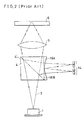
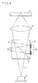
- FIG.1 shows the conventional optical head using the astigmatic method.
- laser light 3 emitted from a semiconductor laser 1 is made into collimated light by a collimation lens 2, and then passes through a beam splitter 4, and then converged on an optical disk or the like optical medium by an objective lens 5.
- Light reflected by pits on the optical disk 6 is made collimated light by the objective lens 5, and divided by the beam splitter 4, and then comes in a transmission elliptical Fresnel lens 9, and finally converged on a four-divided photodetector 10.
- the RF read-out signal and focus error signal are picked up, and tracking error signal is read out by known heterodyne method or the like.
- FIG.2 One example of the conventional optical head using the Foucault method is shown in FIG.2.
- a laser beam 3 emitted from a semiconductor laser 1 is, passing a beam splitter 4, converged on an optical disk 6 by objective lens.
- Light reflected by pits on the optical disk 6 passes through the objective lens 5 and reflected by the beam splitter 4 to rightwards direction of FIG.2, and is introduced to a pair of transmission prisms 16A, 16B, whereby the reflected light beam is converged in two-divided manner on an optical detector 14.
- An optical pickup head comprising an optical sensor formed on a substrate, and an optical member adhered on the optical sensor by an adhesive and including a semi-transmissive reflective film adapted to reflect the light emitted from a laser source and to transmit the light returned from a record medium of a disk, wherein the refractive index of the optical member is set so as to be larger than the refractive index of the adhesive.
- the optical member with the reflective film works as a beam splitter splitting the beam into a reflected beam and an oblique refracted beam and the direct incident light causing as stray light an additional noise on the detector is prevented without any coating film by use of this adhesive.
- a reflective film is provided on the optical member on its surface which is opposite to the surface having the detectors to reflect the light reflected from a first detector to a second detector.
- optical means there is no optical means provided which is scattering or reflecting the light beam incident thereto in plural different manners in dependence of the position of the focused spot in relation to the recording face of the recording medium.
- the optical head in accordance with the present invention comprises reflection optical means with astigmatic characteristics or reflection optical means which divides reflection beam into at least two parts, in a path of reflected light beam from optical recording medium.
- optical head in accordance with the present invention is defined by claim 1.
- a reflecting film reflects the light beam reflected at a first detector to a second detector, while according to the invention the light beam reflected at the beam splitter is reflected by the reflecting optical means, passing again through the beam splitter and finally coming to the plural photodetection elements.
- FIG.3 is a sectional view of a configuration of the first embodiment.
- a laser light 3 of wavelength ⁇ of 0.65 ⁇ m issued from a semiconductor laser 1 is made into collimated light by a collimation lens 2 of diameter 5 mm and NA of 0.1, and the collimated light is led through a cubic beam splitter 4 having 9.8 mm edges; and the light is further led to pass through an objective lens 5 of 5 mm diameter and NA of 0.5, and thereby converged on pits on an optical recording medium, such as optical disk 6. Return light reflected by the recording medium e.g. the pits of the optical disk 6 is again converged collimated light by the objective lens 5, and is led into the beam splitter 4.
- the return light is then splitted into two lights in the light splitter 4, the first one being that travels directly downwards, and the other one being the light reflected by a half-mirror 4 ⁇ in the beam splitter 4 changing direction by 90° to rightwards of FIG.3, thereby entering a reflection elliptical Fresnel lens 7A of convergence type having diameter of e.g. 5 mm and having two focal lengths of 10 mm and 9.6 mm in the beam splitter 4 in major axis direction and in minor axis direction, respectively.
- the light beam incident to the reflection elliptical Fresnel lens 7A which is formed on the side face (right vertical side face in FIG.3), is reflected by the reflection elliptical Fresnel lens 7A, and converged on a photo-detector 8, which is a four-divided photodiode or the like photo-detector, formed on the opposite surface of the beam splitter 4 to the surface having the reflection elliptical Fresnel lens 7A.
- the light beam converged on the photodetector 8 makes light image of astigmatism. Therefore, by processing outputs of the four-divided elements of the photodetector 8, reproduced signal, focus error signal and tracking error signal are detected.
- the optical head of the present embodiment has a configuration of folded light path type, wherein light path from reflection elliptical Fresnel lens 7A to photodetector 8 is folded by the Fresnel lens 7A and passes inside the beam splitter 4. Therefore, no redundant outside space like the prior art is necessary, and the space is drastically reduced.
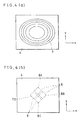
- FIG.4(a) shows front view of the reflection elliptical Fresnel lens 7A formed on the side face of the beam splitter 4
- FIG.4(b) shows disposition of the four-divided elements 8A, 8B, 8C and 8D of the photodetector 8 formed on the side face opposite to the Fresnel lens 7A.
- the reflection elliptical Fresnel lens 7 has gratings of plural elliptical shapes, Which gratings have groove depth of only several ⁇ m, and the periods between neighboring grooves are gradually decreased as the grooves are more of the outer region. And, the gratings are covered with a reflection layer 71.
- the elliptical Fresnel lens has different focal length in major direction and in minor direction; and when light is incident to the reflection elliptical Fresnel lens, the reflected light makes various shapes of focused spot on a vertical light receiving plane, which is the left side wall of the beam splitter 4.
- the focused spot changes its shape to horizontally oblong one when the distance from the Fresnel lens is smaller and changes to round spot, and further changes to vertically oblong one when the distance from the Fresnel lens becomes larger, as a result of astigmatism.
- the reflection elliptical lens 7A can be made by coating an electron beam resist such as CMS or PMMA on a transparent substrate, followed by electron beam exposure with electron dose distribution by using known electron-beam writing system, and further followed by known development.
- the film thickness of the electron resist film is made to have a change of thickness in a direction perpendicular to the elliptical grooves of the Fresnel lens with relief shape of sawtooth cross section; and thereafter a thin film coating of Cr or Al or the like metal or dielectric polylayer thin film is made by evaporation or sputtering on the electron resist.
- the reflection layer is made by sputtering, the deposition of the metal layer can be made in low temperature, and no substantial thermal effect is given to the lens 7, and hence, no deformation of the sawtooth cross section of the Fresnel lens 7 is induced.
- focusing efficiency of the reflection Fresnel lens can be made almost 100 %, excluding the reflection loss at the interface. It is confirmed that as the metal for the reflection layer, a layer using Ag is superior to the layers using Al or Au in smallness of reflection loss, thereby resulting in high efficiency of light utility.
- Fresnel lens 7 As mass-production method of making Fresnel lens 7, a cast die of metal is made by using a Fresnel lens 7 made by electron beam lithography as matrix, and a plenty of plastic Fresnel lens can be made by casting transparent synthetic resin such as transparent epoxy resin, UV-hardening resin, PMMA, or the like therewith. By means of this process, mass-production of optical head in accordance with the present invention can be made. Furthermore, the Fresnel lens 7 can be made by mechanical working by CNC engine lathe or ion beam etch working. Especially the Fresnel lens 7 made by electron beam lithography or focused ion beam lithography has high precision in fine working.
- the former has reflection layer 71 at the grating surface and the groove depth or slope inclination of the former is smaller than that of the latter.
- refractive index of the material constituting the Fresnel lens n
- wavelength of the laser light ⁇
- the depth d in accordance with the present invention is smaller being reduced into of the conventional transmission Fresnel lens.
- the depth of the groove of the present invention is reduced to of the depth d' of the conventional transmission Fresnel lens.
- the reflection Fresnel lens of the present invention is far easier in manufacturing in comparison with the transmission Fresnel lens.
- the depth of the groove of the reflection Fresnel lens is selected to the amount corresponding to the conventional transmission Fresnel lens, its focal length becomes about 1/6 times of that of the transmission Fresnel lens since in the reflection Fresnel lens the diffracted light of 6th order becomes maximum. And thus, a Fresnel lens of the shorter focal length than the transmission focal length is obtainable, and hence, Fresnel lens of higher NA is easily manufacturable.
- an optical head which is miniaturized, has good stability and does not require any adjustment of optical axis, can be configurated; and furthermore, even when the reflection elliptical Fresnel lens 7 and the splitter 4 are not made integral, the optical head can be made small.
- another configuration of folded light beam may be made, by adopting a lens system of a combination of concave lens or convex lens and a cylindrical lens as the optical element having astigmatic characteristics, further provided with Al-coating on the back side (right side of FIG.3) of the combination lens, thereby to constitute reflection type astigmatic lens combination structure, apart from the above-mentioned integral configuration. And such structure is effective for miniaturization of the optical head.
- the photo-detector 8 has PIN structure of amorphous Si, and formed on the surface of the beam splitter 4 by depositing a transparent conductive film of ITO or ZnO of about 1000 ⁇ thickness, and forming thereon a p-type Si film of about, 150 ⁇ by plasma CVD method, and further depositing thereon I-type Si film of about 4000 ⁇ and n-type Si film of about 400 ⁇ thickness in amorphous state. And by means of known photo-lithography the pattern of FIG.4(b), which consists of four square patterns each having 500 ⁇ m edges are formed with 10 ⁇ m cross-shaped gap therebetween to form the four-divided pattern, and further thereon Al-electrodes are formed.
- the optical head can be made very small and its characteristic is stabilized and there is no requirement of light axis alignment. If the above-mentioned advantage of no-requirement of light axis is neglected, a photo-detector made as single crystalline silicon device which is to be bonded or not to be bonded on the beam splitter 4 may be used.
- the beam splitter 4 uses half-mirror 4 ⁇ as the beam splitting means, the light beam is divided into two beams.
- the laser light 3 made collimated by the collimation lens 2 passes through the half-mirror 4 ⁇ of the beam splitter 4 and about half of the light goes towards the optical disk 6.
- the other half of the parallel light is reflected by the half-mirror 4 ⁇ and goes leftwards to the photo-detector 8.
- the above-mentioned latter half light incident to the photo-detector 8 is useless, there is no problem of making undesirable noise on the photodetector 8, since the reflected leftward-travelling light has constant intensity with respect to time.
- the return light reflected from the optical disk 6 about half amount of light passes through the half-mirror 4 ⁇ and goes back to the semiconductor laser 1. And the return light incident to the semiconductor laser 1 can be utilized for making multi-mode operation of the semiconductor laser, and thereby is effective for stabilization of the oscillation.
- the light beam which is induced by reflection of the return light from the optical disk 6 by the half-mirror 4 ⁇ of the beam splitter 4, thereby turning the direction rightwards to the reflection elliptical Fresnel lens 7A, and after reflection by the reflection elliptical Fresnel lens 7A leftwards, and again reflected by the half-mirror 4 ⁇ and hence towards the optical disk 6.
- the reflected light incident to the optical disk 6 makes no substantial effect on the optical disk 6, because the last-mentioned reflected light by half-mirror 4 ⁇ is subject to astigmatism, and further converged by the objective lens 5; and therefore this reflected light becomes out of focus state on the optical disk 6, and makes no substantial undesirable effect on the operation of the optical head, though slight background noise is induced by the last-mentioned reflection light.
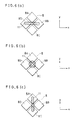
- the beam splitter 4 in the above-mentioned embodiment of FIG.3 is configurated to have a square shape on a sectional plane which is vertical to the plane of beam splitting half-mirror 4 ⁇ , but several other beam splitters may be used.
- FIG.5(a) shows a modified beam splitter wherein the section on a sectional plane which is vertical to the plane of beam splitting half-mirror 4 ⁇ is rectangle; and FIG.5(b) shows another modified example of the beam splitter wherein the face on which the reflection elliptical Fresnel lens 7A is formed is made oblique to the light axis of the incident collimated light, hence the outside shape of the beam splitter is trapezoid.
- the redundant reflected laser light 3A which is the light beam from the reflection elliptical Fresnel lens 7A and reflected by the beam splitting plane 4 ⁇ goes out of the beam splitter 4 in the light path shown by the dotted lines which is led to a direction different from the objective lens 5 or the optical disk 6. Therefore, no undesirable influence is made on reading of pits on the optical disk 6 by such redundant reflected light, and accordingly background noise induced by such redundant reflected light beams is eliminated.
- the reflection elliptical Fresnel lens 7A is constituted as an off-axis Fresnel lens wherein, even when the incident laser light is on the optical axis of the Fresnel lens, the reflected output light is oblique to the incident light and makes astigmatism.
- Such off-axis Fresnel lens makes similar effect to the examples of FIG.5(a) and FIG.5(b) wherein the light reflected by the reflection elliptical Fresnel lens and further reflected by the light splitting plane is emitted with a certain angle to the direction of the original laser beam incident to the beam splitter.
- FIG.6(a), FIG.6(b) and FIG.6(c) show three varieties of light spot converged on the photo-detector 8.
- the focus error signal becomes positive value. Therefore, by utilizing the changes of the focus error signal which is made by subtracting sum of the outputs of the elements 8B and 8D from sum of outputs of the elements 8A and 8C, which changes from a positive value, through zero and to a negative value, a focus servo operation can be made.
- the focus servo operation may be made even by using outputs of only two photo-detector elements, for instance, outputs of the elements 8A and 8B, outputs of elements 8B and 8C, outputs of 8C and 8D, or outputs of elements 8D and 8A.
- the aforementioned example of using all the four-divided elements can make stronger output signal.
- signal reproduction of the information of the optical disk can be made by making summing up the output of the optical detection elements 8A, 8B, 8C and 8D.
- the tracking error signal can be made by known differential phase detection method or heterodyne method.
- FIG.7 shows a sectional view showing a second optical head of embodiment of the present invention.
- Corresponding parts and components to the first embodiment of FIG.3 are shown by the same numerals and marks, and the description thereon made in the first embodiment similarly apply. Differences and features of this second embodiment from the first embodiment are as follows.
- a polarizing beam splitter 4A is used instead of the ordinary beam splitter 4 in the first embodiment; and a quater-wave plate 12A is provided between the upper face of the polarizing splitter 4A and the objective lens 5.
- a second quater-wave plate 12B is provided between the right side face of the beam splitter 4A and the reflection elliptical Fresnel lens 7A.
- the quater-wave plates 12A and 12B are bonded between the polarizing beam splitter 4A and the reflection elliptical Fresnel lens 7A or these three members are made in integral body, in order to make the optical system compact and stable and further to eliminate need of optical axis alignment; but these members may be made separately if some reason requires such separate configuration.
- the combination of the quater-wave plates 12A and 12B and the polarizing beam splitter 4A light efficiency from the beam splitter to the optical disk and also from the optical disk to the beam splitter 4A and to the photo-detector 8 thereof can be made substantially up to almost 100 %, and can achieve very high light efficiency. Furthermore, undesirable laser beam is eliminated, and light-detection of high SN ratio without background noise is attainable.
- FIG.8 shows a third embodiment of the present invention.
- a beam splitter 4 has a transmission circular collimation lens 2A of aperture 5 mm and NA of 0.1 on the lower face, and as objective lens a transmission circular Fresnel lens 5A of aperture 5 mm and NA 0.5 in integral configuration, besides the reflection elliptical Fresnel lens 7A of the foregoing embodiments.
- the transmission circular Fresnel lenses can be made by substantially the similar manufacturing method to the reflection elliptical Fresnel lens 7A, and all three Fresnel lenses 2A, 5A and 7A have layer thickness of several ⁇ m or less. Therefore, an integral beam splitter 4 comprising three Fresnel lenses thereon can be made much smaller and advantages of stable optical operation and no need of light axis alignment are achievable.
- FIG.9 shows sectional view of an optical head of the fourth embodiment of the present invention.
- Corresponding parts and components to the first embodiment of FIG.3 are shown by the same numerals and marks, and the description thereon made in the first embodiment similarly apply. Differences of this fourth embodiment from the first embodiment are as follows.
- This fourth embodiment of FIG.9 does not have the collimation lens between the laser 1 and the beam splitter 4, and the laser beam which have passed through the beam splitter 4 is converged by the objective lens 5 and focused on the optical disk 6.
- a concave reflection elliptical Fresnel lens 7B is utilized instead of the convex reflection elliptical Fresnel lens 7A of the aforementioned examples.
- the concave reflection elliptical Fresnel lens 7B is an optical element which divergingly reflects laser beam incident thereto by making astigmatism.
- the concave lens 7B is, as is obvious from the comparison between FIG.3 and FIG.9, consists of elliptical gratings with the same periods, but the sectional profile thereof is opposite to the sectional profile of the aforementioned reflection elliptical concave Fresnel lens 7A.
- the laser beam incident to the reflection elliptical Fresnel lens 7B is not collimated light, but a converging spherical wave; and the incident laser light of converging spherical wave is reflected to make astigmatism and diverged by the concave reflection elliptical Fresnel lens 7B, and led to the photodetector 8.
- the optical head in accordance with the present embodiment can be made more compact because of excluding the collimation lens, though optical axis alignment becomes more difficult than the optical head of the first embodiment.
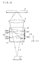
- FIG.10 shows a sectional view showing a fifth optical head of embodiment of the present invention.
- the beam splitter 4A is a polarizing beam splitter
- a quarter-wave plates 12A and 12B are provided on the face opposing the objective lens 5 and on the side face providing the reflection elliptical concave Fresnel lens 7B in a manner to be inserted between the side face of the beam splitter 4A and the reflection elliptical concave Fresnel lens 7B.
- the effect is similar to the optical head of the second embodiment.
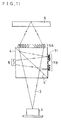
- FIG.11 shows a sectional view showing a sixth optical head of embodiment of the present invention.
- the objective lens 5A is provided on the upper surface of the beam splitter as transmission convex Fresnel lens 5A formed integrally on the beam splitter 4.
- the technical advantage of this embodiment is miniaturization of the optical head similarly to the third embodiment of FIG.8.
- the concave type reflection elliptical Fresnel lens 7B may be replaced by a convex type reflection elliptical Fresnel lens 7A.
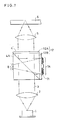
- FIG.12 shows an optical head in accordance with the seventh embodiment of the present invention.
- a laser light 3 of wavelength ⁇ of 0.65 ⁇ m issued from a semiconductor laser 1 is led through a cubic beam splitter 4 having 10 mm edges, and further led to pass through an objective lens 5 of 5 mm diameter and NA of 0.1, and thereby converged on pits on an optical recording medium, much as optical disk 6.
- Return light reflected by the recording medium, e.g. the pits of the optical disk 6 is again converged by the objective lens 5, and is led into the beam splitter 4.
- the return light is then splitted into two lights in the light splitter 4, the first one being that travels directly downwards, and the other one being the light reflected by a half-mirror 4' in the beam splitter 4 changing direction by 90° to rightwards of FIG.12, thereby entering a reflection cylindrical Fresnel lens 13 which comprises two convex reflection Fresnel lenses 13A and 13B disposed in vertical direction (Y) of FIG.12, each having a size of 2.5 mm in Y-direction ⁇ 5 mm in X-direction (perpendicular to the plane of paper) formed integral on the side face of the beam splitter 4.
- the light incident to the convex reflection Fresnel lenses is reflected leftwards, being divided into two beams and converged in vertical (Y) direction only by the Fresnel lenses 13A, 13B, and converged on photo-detector 15 which comprises two pairs of photodetector elements 15A + 15B and 15C + 15D) disposed in vertical (Y) direction of FIG.12. Then, by processing output signals of respective photo-detector elements 15A through 15D, reproduction signal (RF read out signal), focus error signal and tracking error signal are obtained.
- the reproduction signal is obtained by summing up outputs of all four photo-detector elements 15A through 15D; the focus error signal is made by subtracting the output of 15B from the output of 15A, or subtracting the output of 15C from the output of 15D; and the tracking error signal is made by subtracting sum of outputs of 15A and 15B from sum of the outputs of 15C and 15D.
- the optical head of the present embodiment has a configuration of folded light path type, wherein light path from reflections cylindrical Fresnel lens 13 to photo-detector 15 is folded by the Fresnel lens 13 and passes inside the beam splitter 4. Therefore, no redundant outside space like the prior art is necessary, and the space is drastically reduced.
- FIG.13(a) shows front view of the reflection cylindrical Fresnel lens formed on the side face of the beam splitter 4, and
- FIG.13(b) shows disposition of the four elements 15A, 15B, 15C, 15D of the photo-detector 15 formed on the side face opposite to the Fresnel lens 13.
- the reflection cylindrical Fresnel lens 13 comprises a pair of reflection cylindrical Fresnel lenses 13A and 13B, which are disposed in vertical row. Respective reflection cylindrical Fresnel lenses 13A and 13B have linear parallel gratings, which have groove depth of only several ⁇ m, and the periods between neighboring grooves are gradually decreased as the groove are more of the outer region (namely upper and lower from respective center horizontal line). And, the gratings are covered with a reflection layer. When light is incident to the reflection cylindrical Fresnel lens, the reflected light is converged in vertical direction only and is projected on a vertical light receiving plane, which is the left side wall of the beam splitter 4. As modified embodiment, a focusing grating which consists of a construction of a part of the reflection cylindrical Fresnel lens can be used for carrying out the same function.
- the reflection cylindrical lens 13 can be made: by coating an electron beam resist such as CMS or PMMA on a transparent substrate, followed by electron beam exposure with electron dose distribution by using known electron-beam writing system, and further followed by known development. Thereby, the film thickness of the electron resist film is made to have a change of thickness in a direction perpendicular to the grooves of the Fresnel lens of relief shape of sawtooth cross section; and thereafter a thin film coating of Cr or Al or the like metal or dielectric polylayer thin film is made by evaporation or sputtering on the electron resist.
- an electron beam resist such as CMS or PMMA
- the film thickness of the electron resist film is made to have a change of thickness in a direction perpendicular to the grooves of the Fresnel lens of relief shape of sawtooth cross section
- a thin film coating of Cr or Al or the like metal or dielectric polylayer thin film is made by evaporation or sputtering on the electron resist.
- the deposition of the metal layer can be made in low temperature, and no substantial thermal effect is given to the lens 13, and hence, no deformation of the sawtooth cross section of the Fresnel lens 13 is induced. And therefore, focusing efficiency of the reflection Fresnel lens can be made above 80 %, excluding the reflection loss at the interface. It is confirmed that as the metal for the reflection layer, a layer using Ag is superior to the layers using Al or Au in smallness of reflection loss, thereby resulting in high efficiency of light utility.
- Fresnel lens As mass-production method of making Fresnel lens, a cast die of metal is made by using a Fresnel lens 13 made by electron beam lithography as matrix, and a plenty of plastic Fresnel lens can be made by casting of transparent synthetic resin such as transparent epoxy resin, UV-hardening resin, PMMA, or the like therewith. By means of this process, mass-production of optical head in accordance with the present invention can be made. Furthermore, the Fresnel lens can be made by mechanical working by CNC engine lathe or ion beam etch working. Especially the Fresnel lens made by electron beam lithography or focused ion beam lithography has high precision in fine working.
- the photo-detector 15 has PIN structure of amorphous Si, and formed on the surface of the beam splitter 4, by depositing a transparent conductive film of ITO or ZnO of about 1000 ⁇ thickness, and forming thereon a p-type Si film of about 150 ⁇ by plasma CVD method, and further depositing thereon I-type Si film of about 4000 ⁇ and n-type Si film of about 400 ⁇ thickness in amorphous state.
- FIG.13(b) which consists of two-divided (upper and lower) rectangle patterns each having 250 ⁇ m, 500 ⁇ m heights and width edges, are formed with 10 ⁇ m horizontal gap therebetween to form the two-divided pattern, and further thereon Al-electrodes are formed.
- the two-divided photo-detector 15 may be made by more easily by use of P-N type structure or Schottky barrier type structure, though response speed thereof are slower than the PIN configuration.
- other Si compound e.g.
- the optical head can be made very small and its characteristic is stabilized and there is no requirement of light axis alignment. If the above-mentioned advantage of no-requirement of light axis is neglected, a photo-detector made as single crystalline silicon device which is to be bonded or not to be bonded on the beam splitter 4 may be used.
- the beam splitter 4 uses half-mirror 4 ⁇ as the beam splitting means, the light beam is divided into two beams.
- the laser light 3 emitted from the semiconductor laser 1 is led in and passes through the half-mirror 4 ⁇ of the beam splitter 4, and about half of the light goes towards the optical disk 6.
- the other half of the collimated light is reflected by the half-mirror 4 ⁇ and goes leftwards to the photo-detector 15.
- the above-mentioned latter half light incident to the photo-detector 15 is useless, there is no problem of making undesirable noise on the photodetector 15, since the reflected leftwards-travelling light has constant intensity with respect to time.
- the return light reflected from the optical disk 6 about half amount of light passes through the half-mirror 4 ⁇ and goes back to the semiconductor laser 1. And the return light incident to the semiconductor laser 1 can be utilized for making multi-mode operation of the semiconductor laser, and thereby is effective for stabilization of the oscillation.
- the light beam which is induced by reflection of the return light from the optical disk 6 by the half-mirror 4' of the beam splitter 4, thereby turning the direction rightwards to the reflection cylindrical Fresnel lens 13, and after reflection by the reflection cylindrical Fresnel lens 13 leftwards, and again reflected by the half-mirror 4' and hence towards the optical disk 6.
- the reflected light incident to the optical disk 6 makes no substantial effect on the optical disk 6, because the last-mentioned reflected light by half-mirror 4' is coverved wave, and further converged by the objective lens 5; and therefore this reflected light becomes out of focus state on the optical disk 6, and makes no substantial undesirable effect on the operation of the optical head, though negligibly small background noise is induced by the last-mentioned reflection light.
- the beam splitter 4 in the above-mentioned embodiment of FIG.12 is configurated to have a square shape on a sectional plane which is vertical to the plane of beam splitting half-mirror 4', but several other beam splitters may be used.
- FIG.14(a) shows a modified beam splitter wherein the section on a sectional plane which is vertical to the plane of beam splitting half-mirror 4' is rectangle; and FIG.14(b) shows another modified example of the beam splitter wherein the face on which the reflection elliptical Fresnel lens 13 is formed is made oblique to the light axis of the incident collimated light, hence the outside shape of the beam splitter is trapezoid.
- the redundant reflected laser lights which are the light beam from the reflection cylindrical Fresnel lenses 13A and 13B and reflected by the beam splitting plane 4' goes out of the beam splitter 4 in the light path 3A' and 3B' shown by the dotted lines which is led to a direction different from the objective lens 5 or the optical disk 6. Therefore, no undesirable influence is made on reading of pits on the optical disk 6 by such redundant reflected light, and accordingly background noise induced by such redundant reflected light beams is eliminated.
- the reflection cylindrical Fresnel lens 13 is constituted as an off-axis Fresnel lens wherein, even when the incident laser light is on the optical axis of the Fresnel lens, the reflected output light is oblique to the incident light and is converging only in one direction.
- Such off-axis Fresnel lens makes similar effect to the examples of FIG.14(a) and FIG.14(b) wherein the light reflected by the reflection cylindrical Fresnel lens and further reflected by the light splitting plane is emitted with a certain angle to the direction of the original laser beam incident to the beam splitter.
- FIG.15(a), FIG.15(b) and FIG.15(c) show three varieties of light spot converged on the photo-detector 15.
- the light spots 17A and 17B are vertically narrow and lie balanced on the photo-detectors 15A and 15B and on the photo-detectors 15C and 15D as shown in FIG.15(b).
- two elements of the two-divided photodetectors 15A and 15B, or 15C and 15D receive substantially equal amounts of light, and hence focus error signal which is made by subtracting output of photodetection element 15B from output of element 15A or the element 15C from output of the element 15D is zero.
- focus error signal which is made by subtracting output of photodetection element 15B from output of element 15A or the element 15C from output of the element 15D is zero.
- the focus error signal becomes negative value. Therefore, by utilizing the changes of the focus error signal which is made by subtruating output of the element 15B from output of the element 15A or output of the element 15C from output of the element 15D, which changes from a positive value, through zero and to a negative value, a focus servo operation can be made. Furthermore, signal reproduction of the information of the optical disk can be made by making summing up the output of the optical detection elements 15A, 15B, 15C and 15D.
- Tracking error signal can be made by known push-pull method, which utilizes a phenomenon that an inbalance of intensity distributions of reflected light is produced when light spot on the optical disk 6 focused by the objective lens 5 makes a misregistration from the center line of the signal track on the optical disk 6.
- the tracking error signal is made by subtracting sum of outputs of photo-detector elements 15C and 15D from sum of outputs of photo-detector elements 15A and 15B. And the tracking error signal is zero when the light spot lies at the center line of the signal track, and the track error signal becomes positive or negative when the light spot deviates on one side or the opposite side from the center line. Therefore, by utilizing the tracking error signal, a tracking servo-control can be made.
- the case is what uses a photo-detector consisting of two pairs of each two-divided photo-detector element configuration; but so far as is capable of carrying out focus servo-control and tracking servo-control, any other configuration of photo-detector can be used. It is sufficient that there is one photo-detector of two-divided configuration for the focus servo-control, and for the tracking servo-control a configuration of two pairs of is enough.
- reflection cylindrical Fresnel lens is used as the reflection optical element for dividing the light beam at least in two. Since the optical element can make light converging and light diverging action in one direction depending on the convex type or concave type of the cylindrical lens, convergence of light beam on the photo-detector 15 can be made irrespective of the positional relation between the semiconductor laser 1 and the beam splitter 4. Furthermore, even when circular or elliptical reflection Fresnel lens is used as the reflection optical element, the similar effect is obtainable, though manufacturing thereof is more difficult than the reflection cylindrical Fresnel lens.
- the concave reflection Fresnel lens is similarly obtainable by oppositely changing the cross-section profile of the Fresnel lens 13 to that of the convex reflection cylindrical Fresnel lens 13 shown in FIG.12.
- FIG.16 shows a sectional view showing an eighth optical head of embodiment of the present invention.
- Corresponding parts and components to the seventh embodiment of FIG.12 are shown by the same numerals and marks, and the description thereon made in the first embodiment similarly apply. Differences and features of this eighth embodiment from the seventh embodiment are as follows.
- a polarizing beam splitter 4A is used instead of the ordinary beam splitter 4 in the seventh embodiment; and a quater-wave plate 12A is provided between the upper face of the polarizing splitter 4A and the objective lens 5.
- a second quater-wave plate 12B is provided between the right side face of the beam splitter 4A and the reflection cylindrical Fresnel lens 13.
- the quater-wave plate 12B is bonded between the polarizing beam splitter 4A and the reflection cylindrical Fresnel lens 13 or these three members are made in integral body, in order to make the optical system compact and stable and further to eliminate need of optical axis alignment; but these members may be made separately if some reason requires such separate configuration.
- the combination of the quater-wave plates 12A and 12B and the polarizing beam splitter 4A light efficiency from the beam splitter to the optical disk and also from the optical disk to the beam splitter 4A and to the photo-detector 15 thereof can be made substantially up to almost 100 %, and can achieve very high light efficiency. Furthermore, undesirable laser beam is eliminated, and light-detection of high SN ratio without background noise is attainable.
- FIG.17 shows a ninth embodiment of the present invention.
- a beam splitter 4 has as objective lens a transmission circular Fresnel lens 5A of aperture 5 mm and optical disk side NA 0.5 in integral configuration, besides the reflection cylindrical Fresnel lens 13 of the above-mentioned embodiment.
- the transmission circular Fresnel lens 5A can be made by substantially the similar manufacturing method to the reflection cylindrical Fresnel lens 13, and both the Fresnel lenses 13 and 5A have layer thickness of several ⁇ m or less. Therefore, an integral beam splitter 4 comprising three Fresnel lenses thereon can be made easily and advantages of stable optical operation and no need of light axis alignment is achievable.
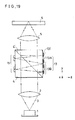
- FIG.18 shows sectional view of an optical head of a tenth embodiment of the present invention.
- Corresponding parts and components to the seventh embodiment of FIG.12 are shown by the same numerals and marks, and the description thereon made in the seventh embodiment similarly apply.
- Differences of this tenth embodiment from the seventh embodiment are as follows.
- This tenth embodiment of FIG.18 has reflection grating 18 consisting of two reflection gratings 18A and 18B which are formed integral with the beam splitter 4.
- This refection grating 18 is made as linear grating with uniform period.
- the grating grooves in X-axis direction are made parallelly, and sawtooth relief shapes of the gratings 18A and 18B are disposed each other in symmetry.
- reflection layer 181 is deposited on the surface of the sawtooth grating.
- the manufacturing of the grating becomes easier than the afore-mentioned reflection Fresnel lenses.
- modified gratings having variations of period can be adopted. For instance, as one of the period-changing gratings, the reflection cylindrical Fresnel lens disclosed in the seventh embodiment is classified.
- such grating as linear grating with uniform period wherein cross-sectional profile of the grating is, for instance, rectangular, isosceles triangle, sinusoidal shape or such symmetrical shape.
- lowest point of the bottom and highest point of the peak of the shape lie at substantial center part of the bottom and the peak, respectively, and such grating generates diffraction light almost in symmetry, and both of +1 order light and -1 order light can be utilized. Accordingly, there is no use of making the sawtooth shapes of the respective elementally cylindrical lens parts 18A and 18B disposing in each other opposite directions.
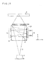
- FIG.19 shows a sectional view showing eleventh optical head of embodiment of the present invention.
- Corresponding parts and components to the seventh embodiment of FIG.12 are shown by the same numerals and marks, and the description thereon made in the seventh embodiment similarly apply.
- Difference of this eleventh embodiment from the seventh embodiment is as follows. Principal difference of the present embodiment from the seventh embodiment is that a collimation lens 2 is provided between the semiconductor laser 1 and the lower face of the beam splitter 4. In this embodiment, the laser light in the beam splitter 4 is collimated until entering the reflection cylindrical Fresnel lens 13, and therefore, alignment of light axis is very easy.
- For the reflection optical element for dividing the light beam after the reflection function of converging the light beam in the vertical (Y) direction is necessary, and therefore Fresnel lens or focusing grating is effective as the optical element.
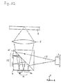
- FIG.20 shows a sectional view showing a twelfth optical head of embodiment of the present invention.
- Corresponding parts and components to the seventh embodiment of FIG.12 are shown by the same numerals and marks, and the description thereon made in the seventh embodiment similarly apply.
- Differences of this twelfth embodiment from the seventh embodiment are as follows.
- reflection prism 19 comprising two prisms 19A and 19B of mutually symmetric disposition is used as shown in FIG.20, and these have reflection layers similar to the foregoing embodiments.
- the splitted and 90° turned light beam is divided into two reflected beams, which are led to the upper photo-detectors 15A + 15B and the lower photo-detectors 15C + 15D, respectively.
- FIGs. 21 and 22 show thirteenth and fourteenth embodiments.
- an optical head may be configurated such that the beam splitter 4 is turned so that the light incident face and the face having the reflection optical elements 7A or 7B or 13 or 18 or 19 are each other interchanged, as shown in FIG.21 and FIG.22.
- Such optical head has reduced vertical size from the optical disk 6 to the beam splitter 4.
- the objective lens and collimation lens are referred so for the convenience of description, but these are the same as the lenses generally used for optical system.
- This invention is applicable not only to the optical head for optical disk, but also to any other optical recording or reproducing apparatus, similarly.
Claims (28)
- Ein optischer Kopf, der folgende Elemente aufweist:
eine Lichtquelle (1) zum Emittieren eines Lichtstrahls (3),
einen Strahlteiler (4) zum Aufteilen des Laserlichtstrahls (3), der auf seine Lichteinfallsfläche einfällt, in wenigstens zwei Lichtstrahlen, einer in gerader Richtung und der andere in einer davon verschiedenen Richtung,
eine Objektivlinse (5) zum Fokussieren eines Lichtes, das von dem Strahlteiler (4) aufgeteilt wurde, um einen fokussierten Punkt zu erzeugen und ihn auf eine optische Aufnahmeeinrichtung (6) zu projizieren, um ein Rückkehrlicht zu erzeugen, das von der optischen Aufnahmeeinrichtung (6) reflektiert wird,
eine Photodetektoreinrichtung (8,15), die mehrere Photodetektionselemente (8a-D,15A-D) aufweist, die auf oder oberhalb einer Fläche des Strahlteilers (4) vorgesehen sind,
eine optische Einrichtung (7,13,18,19), die auf oder oberhalb einer Rückkehrlichtausgangsfläche vorgesehen ist, die eine andere als eine Rückkehrlichtausgangsfläche ist, zu der die Lichtquelle (1) entgegengesetzt ist bezüglich des Rückkehrlichtes von der optischen Aufnahmeeinrichtung (6),
wobei die optische Einrichtung (7,13,18,19) einen Lichtstrahl, der auf sie einfällt, auf viele verschiedene Weisen streut, wobei es eine erste Weise ist, daß, wenn der fokussierte Punkt näher als die Aufnahmefläche des Aufnahmemediums (6) erzeugt wird, sein reflektierter Lichtstrahl ein erstes Bild erzeugt, um den Photodetektor (8,15) zu veranlassen, ein erstes Signal auszugeben, wenn der fokussierte Punkt weiter entfernt als die Aufnahmefläche erzeugt wird, sein reflektiertes Licht ein zweites Bild erzeugt, um den Photodetektor zu veranlassen, ein zweites Signal auszugeben, und wenn der fokussierte Punkt genau auf der Aufnahmefläche erzeugt wird, sein reflektierter Lichtstrahl ein drittes Bild erzeugt, um zu bewirken, daß der Photodetektor (8,15) ein drittes Signal ausgibt,
dadurch gekennzeichnet,
daß die optische Einrichtung (7,13,18,19) eine reflektierende optische Einrichtung (7,13,18,19) ist, die die Streuung des Lichtstrahls, der auf sie einfällt, auf viele verschiedene Weisen als Reflektion bewirkt, und
daß die Photodetektoreinrichtung (8,15) auf der Oberfläche des Strahlteilers (4) vorgesehen ist, die entgegengesetzt zu der Fläche mit der optischen Einrichtung (7,13,18,19) ist. - Ein optischer Kopf nach Anspruch 1, wobei die optische Reflexionseinrichtung ein astigmatisches optisches Element (7) zum Erzeugen eines astigmatischen Lichtstrahls ist, der dabei reflektiert wird und in dem Strahlteiler (4) zu dem Photodetektor (8) wandert, und
daß die Photodetektoreinrichtung (8) wenigstens zwei geteilte Detektorelemente (8A+B) hat. - Ein optischer Kopf nach Anspruch 1, wobei die optische Reflexionseinrichtung ein Strahlteilerelement (13,18,19) ist, um den Lichtstrahl in wenigstens zwei Lichtstrahlen aufzuteilen, die in dem Strahlteiler (4) zu dem Photodetektor (15) hin wandern, und
daß die Photodetektoreinrichtung wenigstens ein Paar von Photodetektoren (15A+B, 15C+D) hat, wobei wenigstens ein Paar von dem Paar von Photodetektoren wenigstens zwei unterteilte Teile (15A+B) aufweist. - Ein optischer Kopf nach Anspruch 1, wobei die optische Reflexionseinrichtung ein Diffraktionselement (18) ist, das eine Diffraktion bzw. Beugung von einfallendem Licht bewirkt.
- Ein optischer Kopf nach Anspruch 1, wobei die optische Reflexionseinrichtung (7,13,18,19) integral mit dem Strahlteiler (4) ausgebildet ist.
- Ein optischer Kopf nach Anspruch 1, wobei der Photodetektor (8,15) integral mit dem Strahlteiler (4) ausgebildet ist.
- Ein optischer Kopf nach Anspruch 1, wobei der Photodetektor (8,15) vom PIN-Typ, PN-Typ oder Schottky-Grenztyp aus amorphem Si, amorphem SiGe oder amorphem SiSn oder amorphem SiGeSn ist, das auf einem transparenten leitenden Film ausgebildet ist.
- Ein optischer Kopf nach Anspruch 1, wobei der Strahlteiler (4) ein polarisierender Strahlteiler ist,
eine Viertel-Wellenlängen-Platte (12A) zwischen dem Strahlteiler (4) und der Objektivlinse (5) vorgesehen ist, und
eine andere Viertel-Wellenlängen-Platte (12B) zwischen dem Strahlteiler (4) und der optischen Reflexionseinrichtung (7,13) vorgesehen ist. - Ein optischer Kopf nach Anspruch 8, wobei der Strahlteiler (4) und wenigstens eine der Viertel-Wellenlängen-Platten (12A,B) integral miteinander ausgebildet sind.
- Ein optischer Kopf nach Anspruch 8, wobei die optische Reflexionseinrichtung (7,13) integral mit der Viertel-Wellenlängenplatte (12A,B) ausgebildet ist.
- Ein optischer Kopf nach Anspruch 1, wobei eine Sammellinse (2) zwischen der Strahllichtquelle (1) und dem Strahlteiler (4) vorgesehen ist und die optische Reflexionseinrichtung (7,13,18) fokussierende Eigenschaften hat.
- Ein optischer Kopf nach Anspruch 11, wobei die Sammellinse (2) eine Transmissions-Fresnel-Linse (2A) ist.
- Ein optischer Kopf nach Anspruch 1, wobei die Objektivlinse (5) eine Transmissions-Fresnel-Linse (5A) ist.
- Ein optischer Kopf nach Anspruch 11, wobei die Sammellinse (2) und der Strahlteiler (4) integral ausgebildet sind.
- Ein optischer Kopf nach Anspruch 1, wobei die Objektivlinse (5) und der Strahlteiler (4) integral ausgebildet sind.
- Ein optischer Kopf nach Anspruch 1, wobei der Strahlteiler (4) einen nichtquadratischen vierseitigen Querschnitt bei einer Ebene, die senkrecht zu der Strahlteilungsebene (4') des Strahlteilers (4) und parallel mit den optischen Achsen der Lichtstrahlen darin ist, besitzt.
- Ein optischer Kopf nach Anspruch 1, wobei die optische Reflexionseinrichtung (7,13,18,19) aus transparentem Kunstharz ist.
- Ein optischer Kopf nach Anspruch 2, wobei der Photodetektor (8,15) von einer viergeteilten Struktur ist.
- Ein optischer Kopf nach Anspruch 2, wobei das astigmatische optische Element eine elliptische Reflexions-Fresnel-Linse (7) ist.
- Ein optischer Kopf nach Anspruch 2, wobei das astigmatische optische Element eine astigmatische Reflexions-Fresenel-Linse (7) des Typs abseits von der Achse ist.
- Verfahren zum Herstellen eines optischen Kopfes nach Anspruch 1, wobei eine Reflexionsschicht (71,131,181,191) auf der optischen Reflexionseinrichtung (7,13,18,19) durch ein Sputter- bzw. Aufstäubverfahren aufgetragen wird.
- Ein optischer Kopf nach Anspruch 4, wobei das Diffraktions- bzw. Beugungselement aus Gittern (18) mit einem Sägezahn-Reliefprofil besteht.
- Ein optischer Kopf nach Anspruch 1, wobei die Reflexionsschicht (71,131,181,191) der optischen Reflexionseinrichtung eine Ag-Schicht ist.
- Ein optischer Kopf nach Anspruch 3, wobei das strahlteilende Element eine kreisförmige oder elliptische Reflexions-Fresnel-Linse oder eine zylindrische Reflexions-Fresnel-Linse (13) oder ein lineares zylindrisches Reflexionsgitter (18) oder ein fokussierendes Reflexionsgitter (18) ist.
- Ein optischer Kopf nach Anspruch 24, wobei die Reflexions-Fresnel-Linse (7,13) eine Fresnel-Linse von dem Typ abseits der Achse ist.
- Ein optischer Kopf nach Anspruch 3, wobei das strahlteilende Element (13,18,19) aus Reflexionsprismen besteht.
- Ein optischer Kopf nach Anspruch 24, wobei das lineare Reflexionsgitter (18) eine gleichförmige Periode besitzt.
- Ein optischer Kopf nach Anspruch 24, wobei das lineare Reflexionsgitter (18) ein symmetrisches Reliefprofil besitzt.
Applications Claiming Priority (4)
| Application Number | Priority Date | Filing Date | Title |
|---|---|---|---|
| JP62061562A JPS63228428A (ja) | 1987-03-17 | 1987-03-17 | 光学ヘツド |
| JP61562/87 | 1987-03-17 | ||
| JP115019/87 | 1987-05-12 | ||
| JP62115019A JPS63279439A (ja) | 1987-05-12 | 1987-05-12 | 光学ヘッド |
Publications (3)
| Publication Number | Publication Date |
|---|---|
| EP0283002A2 EP0283002A2 (de) | 1988-09-21 |
| EP0283002A3 EP0283002A3 (de) | 1991-03-27 |
| EP0283002B1 true EP0283002B1 (de) | 1994-02-16 |
Family
ID=26402611
Family Applications (1)
| Application Number | Title | Priority Date | Filing Date |
|---|---|---|---|
| EP88104200A Expired - Lifetime EP0283002B1 (de) | 1987-03-17 | 1988-03-16 | Optischer Kopf |
Country Status (3)
| Country | Link |
|---|---|
| US (1) | US4870632A (de) |
| EP (1) | EP0283002B1 (de) |
| DE (1) | DE3887762T2 (de) |
Cited By (1)
| Publication number | Priority date | Publication date | Assignee | Title |
|---|---|---|---|---|
| DE102005004419A1 (de) * | 2005-01-31 | 2006-08-03 | Sick Ag | Optoelektronischer Sensor |
Families Citing this family (24)
| Publication number | Priority date | Publication date | Assignee | Title |
|---|---|---|---|---|
| EP0334601B1 (de) * | 1988-03-25 | 1994-09-07 | Tosoh Corporation | Fehlerdetektorvorrichtung für einen optischen Abtastkopf |
| JP2730756B2 (ja) * | 1988-04-13 | 1998-03-25 | 日立建機株式会社 | 超音波探触子及びその製造方法 |
| JPH0478029A (ja) * | 1990-07-13 | 1992-03-12 | Toshiba Corp | 光学的情報記録再生装置 |
| US5138495A (en) * | 1990-07-27 | 1992-08-11 | Matsushita Electric Industrial Co., Ltd. | Diffractive optical lens |
| JP2617237B2 (ja) * | 1990-08-28 | 1997-06-04 | シャープ株式会社 | 光スポット位置検出装置 |
| US5281802A (en) * | 1991-02-20 | 1994-01-25 | Ricoh Company, Ltd. | Focus error signal detection device with separating prism |
| US5446710A (en) * | 1992-11-06 | 1995-08-29 | International Business Machines Corporation | Focus error detection using an equal path length lateral shearing interferometer |
| KR100200828B1 (ko) * | 1994-07-30 | 1999-06-15 | 윤종용 | 포커스에러 검출장치 |
| US6147802A (en) * | 1994-12-28 | 2000-11-14 | Seiko Epson Corporation | Polarization luminaire and projection display |
| EP0745983A3 (de) * | 1995-05-31 | 1998-03-04 | Daewoo Electronics Co., Ltd | Optischer Aufnahmekopf |
| EP0749119A3 (de) * | 1995-05-31 | 1997-08-20 | Daewoo Electronics Co Ltd | Optisches Abtastgerät |
| KR970050336A (ko) * | 1995-12-28 | 1997-07-29 | 구자홍 | 광픽업장치 |
| KR19980029872A (ko) * | 1996-10-28 | 1998-07-25 | 배순훈 | 광 픽-업장치 |
| KR19980058055A (ko) * | 1996-12-30 | 1998-09-25 | 배순훈 | 광 픽업 장치 |
| US6167016A (en) * | 1997-04-11 | 2000-12-26 | Aerial Imaging Corporation | Optical head with a diffractive lens for focusing a laser beam |
| JPH11273119A (ja) * | 1998-03-24 | 1999-10-08 | Pioneer Electron Corp | 光学式ピックアップ装置 |
| JP2000321021A (ja) * | 1999-05-10 | 2000-11-24 | Canon Inc | 干渉装置、変位測定装置、及びそれを用いた情報記録又は/及び再生装置 |
| US6243126B1 (en) * | 2000-03-09 | 2001-06-05 | Toshiba Tec Kabushiki Kaisha | Image forming apparatus in which a laser beam is applied from a semiconductor laser to scan an image carrier, and method of controlling the apparatus |
| DE10125469B4 (de) * | 2001-05-25 | 2008-01-10 | Leica Microsystems Cms Gmbh | Vorrichtung zur Ermittlung einer Lichtleistung, Mikroskop und Verfahren zur Mikroskopie |
| KR100480630B1 (ko) * | 2002-11-13 | 2005-03-31 | 삼성전자주식회사 | 노이즈를 줄일 수 있도록 된 광픽업 및 편광변환기 |
| JP4655025B2 (ja) | 2006-09-07 | 2011-03-23 | パナソニック株式会社 | 光ピックアップ装置 |
| JP4853424B2 (ja) * | 2007-08-07 | 2012-01-11 | パナソニック株式会社 | 光ピックアップ装置 |
| WO2019137620A1 (en) * | 2018-01-12 | 2019-07-18 | Iris Industries Sa | Short-wave infrared detector and its integration with cmos compatible substrates |
| US11579014B1 (en) * | 2020-08-20 | 2023-02-14 | Amazon Technologies, Inc. | Optical detector system |
Citations (1)
| Publication number | Priority date | Publication date | Assignee | Title |
|---|---|---|---|---|
| EP0278406A2 (de) * | 1987-02-06 | 1988-08-17 | Sony Corporation | Optischer Lesekopf |
Family Cites Families (7)
| Publication number | Priority date | Publication date | Assignee | Title |
|---|---|---|---|---|
| NL8104588A (nl) * | 1981-10-08 | 1983-05-02 | Philips Nv | Bundelscheidingsprisma, werkwijze voor het vervaardigen van dit prisma en van dit prisma voorziene optische lees- en/of schrijfeenheid. |
| US4441175A (en) * | 1982-01-25 | 1984-04-03 | Magnetic Peripherals Inc. | Partial beam focus sensing in an optical recording system |
| NL8303932A (nl) * | 1982-11-17 | 1984-06-18 | Pioneer Electronic Corp | Opneeminrichting voor optische plaat. |
| EP0137272B1 (de) * | 1983-09-05 | 1991-06-19 | Mitsubishi Denki Kabushiki Kaisha | Automatisches Fokussierungsverfahren |
| JPS60187941A (ja) * | 1984-03-08 | 1985-09-25 | Seiko Instr & Electronics Ltd | 光情報検出装置 |
| JPS61289544A (ja) * | 1985-06-14 | 1986-12-19 | Canon Inc | 光ヘツド装置 |
| JPS621141A (ja) * | 1985-06-27 | 1987-01-07 | Matsushita Electric Ind Co Ltd | 光学ヘツド |
-
1988
- 1988-03-16 EP EP88104200A patent/EP0283002B1/de not_active Expired - Lifetime
- 1988-03-16 DE DE3887762T patent/DE3887762T2/de not_active Expired - Fee Related
- 1988-03-17 US US07/169,478 patent/US4870632A/en not_active Expired - Lifetime
Patent Citations (1)
| Publication number | Priority date | Publication date | Assignee | Title |
|---|---|---|---|---|
| EP0278406A2 (de) * | 1987-02-06 | 1988-08-17 | Sony Corporation | Optischer Lesekopf |
Cited By (2)
| Publication number | Priority date | Publication date | Assignee | Title |
|---|---|---|---|---|
| DE102005004419A1 (de) * | 2005-01-31 | 2006-08-03 | Sick Ag | Optoelektronischer Sensor |
| US7463419B2 (en) | 2005-01-31 | 2008-12-09 | Sick Ag | Optoelectronic sensor |
Also Published As
| Publication number | Publication date |
|---|---|
| DE3887762T2 (de) | 1994-09-08 |
| EP0283002A3 (de) | 1991-03-27 |
| US4870632A (en) | 1989-09-26 |
| EP0283002A2 (de) | 1988-09-21 |
| DE3887762D1 (de) | 1994-03-24 |
Similar Documents
| Publication | Publication Date | Title |
|---|---|---|
| EP0283002B1 (de) | Optischer Kopf | |
| US5060212A (en) | Integrated optical pick-up device | |
| JP2532818B2 (ja) | 対物レンズおよび光ヘッド装置 | |
| US4733065A (en) | Optical head device with diffraction grating for separating a light beam incident on an optical recording medium from a light beam reflected therefrom | |
| EP0747893B1 (de) | Optische Wiedergabekopfvorrichtung für verschiedene Plattentypen | |
| US5155622A (en) | Polarizing optical element and device using the same | |
| US6834036B1 (en) | Optical head for a plurality of types of information recording media | |
| EP0692785B1 (de) | Vorrichtung mit optischem Kopf | |
| US5233444A (en) | Focus error detecting apparatus | |
| US5781676A (en) | Waveguide integrated optical pickup device and optical waveguide element | |
| JPH06139612A (ja) | 光学ヘッドとその製造方法 | |
| JPH04318333A (ja) | 光ヘッド装置 | |
| JPS58220248A (ja) | 光学式ピツクアツプ | |
| US5377177A (en) | Optical pickup having first and second reflecting surfaces and hologram | |
| CN100377233C (zh) | 光学头装置及光盘装置 | |
| US5648946A (en) | Optical pick-up apparatus with holographic optical element to diffract both forward and return light beams | |
| JPH08240718A (ja) | 光ヘッド装置 | |
| JPH0822624A (ja) | 光ヘッド装置及び光情報装置 | |
| JPH0746439B2 (ja) | 光ヘツド装置 | |
| JPH0721866B2 (ja) | 光ヘツド装置 | |
| JPS5977637A (ja) | 光学読取装置 | |
| JPH0795373B2 (ja) | 光学式情報読取り装置 | |
| JPH0654548B2 (ja) | 光学式情報再生装置 | |
| JPH09161310A (ja) | 光学装置 | |
| JPH07114025B2 (ja) | 光学式情報再生装置 |
Legal Events
| Date | Code | Title | Description |
|---|---|---|---|
| PUAI | Public reference made under article 153(3) epc to a published international application that has entered the european phase |
Free format text: ORIGINAL CODE: 0009012 |
|
| 17P | Request for examination filed |
Effective date: 19880316 |
|
| AK | Designated contracting states |
Kind code of ref document: A2 Designated state(s): DE FR GB |
|
| PUAL | Search report despatched |
Free format text: ORIGINAL CODE: 0009013 |
|
| AK | Designated contracting states |
Kind code of ref document: A3 Designated state(s): DE FR GB |
|
| RHK1 | Main classification (correction) |
Ipc: G11B 7/09 |
|
| 17Q | First examination report despatched |
Effective date: 19920519 |
|
| GRAA | (expected) grant |
Free format text: ORIGINAL CODE: 0009210 |
|
| AK | Designated contracting states |
Kind code of ref document: B1 Designated state(s): DE FR GB |
|
| REF | Corresponds to: |
Ref document number: 3887762 Country of ref document: DE Date of ref document: 19940324 |
|
| ET | Fr: translation filed | ||
| PLBE | No opposition filed within time limit |
Free format text: ORIGINAL CODE: 0009261 |
|
| STAA | Information on the status of an ep patent application or granted ep patent |
Free format text: STATUS: NO OPPOSITION FILED WITHIN TIME LIMIT |
|
| 26N | No opposition filed | ||
| REG | Reference to a national code |
Ref country code: GB Ref legal event code: 746 Effective date: 19951123 |
|
| REG | Reference to a national code |
Ref country code: FR Ref legal event code: D6 |
|
| REG | Reference to a national code |
Ref country code: GB Ref legal event code: IF02 |
|
| PGFP | Annual fee paid to national office [announced via postgrant information from national office to epo] |
Ref country code: FR Payment date: 20060308 Year of fee payment: 19 |
|
| PGFP | Annual fee paid to national office [announced via postgrant information from national office to epo] |
Ref country code: DE Payment date: 20060309 Year of fee payment: 19 |
|
| PGFP | Annual fee paid to national office [announced via postgrant information from national office to epo] |
Ref country code: GB Payment date: 20060315 Year of fee payment: 19 |
|
| GBPC | Gb: european patent ceased through non-payment of renewal fee |
Effective date: 20070316 |
|
| REG | Reference to a national code |
Ref country code: FR Ref legal event code: ST Effective date: 20071130 |
|
| PG25 | Lapsed in a contracting state [announced via postgrant information from national office to epo] |
Ref country code: DE Free format text: LAPSE BECAUSE OF NON-PAYMENT OF DUE FEES Effective date: 20071002 |
|
| PG25 | Lapsed in a contracting state [announced via postgrant information from national office to epo] |
Ref country code: GB Free format text: LAPSE BECAUSE OF NON-PAYMENT OF DUE FEES Effective date: 20070316 |
|
| PG25 | Lapsed in a contracting state [announced via postgrant information from national office to epo] |
Ref country code: FR Free format text: LAPSE BECAUSE OF NON-PAYMENT OF DUE FEES Effective date: 20070402 |