EP0279727B1 - Conditionnement mélangeur distributeur - Google Patents
Conditionnement mélangeur distributeur Download PDFInfo
- Publication number
- EP0279727B1 EP0279727B1 EP19880400212 EP88400212A EP0279727B1 EP 0279727 B1 EP0279727 B1 EP 0279727B1 EP 19880400212 EP19880400212 EP 19880400212 EP 88400212 A EP88400212 A EP 88400212A EP 0279727 B1 EP0279727 B1 EP 0279727B1
- Authority
- EP
- European Patent Office
- Prior art keywords
- bridge
- package according
- containers
- under
- assembly
- Prior art date
- Legal status (The legal status is an assumption and is not a legal conclusion. Google has not performed a legal analysis and makes no representation as to the accuracy of the status listed.)
- Expired - Lifetime
Links
- 239000000443 aerosol Substances 0.000 claims abstract description 7
- 238000002156 mixing Methods 0.000 claims abstract description 5
- 238000003825 pressing Methods 0.000 claims description 2
- 239000007789 gas Substances 0.000 abstract description 4
- 239000007788 liquid Substances 0.000 abstract description 4
- 238000002360 preparation method Methods 0.000 abstract description 3
- 239000011261 inert gas Substances 0.000 abstract description 2
- 229940126601 medicinal product Drugs 0.000 abstract 1
- 238000004806 packaging method and process Methods 0.000 description 6
- 239000012159 carrier gas Substances 0.000 description 5
- 239000000047 product Substances 0.000 description 5
- 239000007921 spray Substances 0.000 description 4
- 239000003814 drug Substances 0.000 description 3
- 229940079593 drug Drugs 0.000 description 3
- IJGRMHOSHXDMSA-UHFFFAOYSA-N Atomic nitrogen Chemical compound N#N IJGRMHOSHXDMSA-UHFFFAOYSA-N 0.000 description 2
- 238000006243 chemical reaction Methods 0.000 description 2
- 230000000295 complement effect Effects 0.000 description 2
- 239000000126 substance Substances 0.000 description 2
- 239000004215 Carbon black (E152) Substances 0.000 description 1
- 239000000853 adhesive Substances 0.000 description 1
- 230000001070 adhesive effect Effects 0.000 description 1
- 239000001273 butane Substances 0.000 description 1
- 238000001035 drying Methods 0.000 description 1
- 230000000694 effects Effects 0.000 description 1
- 239000012467 final product Substances 0.000 description 1
- 229930195733 hydrocarbon Natural products 0.000 description 1
- 150000002430 hydrocarbons Chemical class 0.000 description 1
- 239000002917 insecticide Substances 0.000 description 1
- 239000011872 intimate mixture Substances 0.000 description 1
- IJDNQMDRQITEOD-UHFFFAOYSA-N n-butane Chemical compound CCCC IJDNQMDRQITEOD-UHFFFAOYSA-N 0.000 description 1
- OFBQJSOFQDEBGM-UHFFFAOYSA-N n-pentane Natural products CCCCC OFBQJSOFQDEBGM-UHFFFAOYSA-N 0.000 description 1
- 229910052757 nitrogen Inorganic materials 0.000 description 1
- 230000003647 oxidation Effects 0.000 description 1
- 238000007254 oxidation reaction Methods 0.000 description 1
- 239000002304 perfume Substances 0.000 description 1
- 238000006116 polymerization reaction Methods 0.000 description 1
- 239000000843 powder Substances 0.000 description 1
- 230000002685 pulmonary effect Effects 0.000 description 1
- 210000002345 respiratory system Anatomy 0.000 description 1
- 230000000717 retained effect Effects 0.000 description 1
- 238000007789 sealing Methods 0.000 description 1
- 239000007790 solid phase Substances 0.000 description 1
- 239000002904 solvent Substances 0.000 description 1
- 238000005507 spraying Methods 0.000 description 1
- 238000003756 stirring Methods 0.000 description 1
- 230000000007 visual effect Effects 0.000 description 1
Images
Classifications
-
- B—PERFORMING OPERATIONS; TRANSPORTING
- B65—CONVEYING; PACKING; STORING; HANDLING THIN OR FILAMENTARY MATERIAL
- B65D—CONTAINERS FOR STORAGE OR TRANSPORT OF ARTICLES OR MATERIALS, e.g. BAGS, BARRELS, BOTTLES, BOXES, CANS, CARTONS, CRATES, DRUMS, JARS, TANKS, HOPPERS, FORWARDING CONTAINERS; ACCESSORIES, CLOSURES, OR FITTINGS THEREFOR; PACKAGING ELEMENTS; PACKAGES
- B65D47/00—Closures with filling and discharging, or with discharging, devices
- B65D47/04—Closures with discharging devices other than pumps
- B65D47/20—Closures with discharging devices other than pumps comprising hand-operated members for controlling discharge
- B65D47/26—Closures with discharging devices other than pumps comprising hand-operated members for controlling discharge with slide valves, i.e. valves that open and close a passageway by sliding over a port, e.g. formed with slidable spouts
- B65D47/261—Closures with discharging devices other than pumps comprising hand-operated members for controlling discharge with slide valves, i.e. valves that open and close a passageway by sliding over a port, e.g. formed with slidable spouts having a rotational or helicoidal movement
- B65D47/263—Closures with discharging devices other than pumps comprising hand-operated members for controlling discharge with slide valves, i.e. valves that open and close a passageway by sliding over a port, e.g. formed with slidable spouts having a rotational or helicoidal movement between tubular parts
-
- B—PERFORMING OPERATIONS; TRANSPORTING
- B65—CONVEYING; PACKING; STORING; HANDLING THIN OR FILAMENTARY MATERIAL
- B65D—CONTAINERS FOR STORAGE OR TRANSPORT OF ARTICLES OR MATERIALS, e.g. BAGS, BARRELS, BOTTLES, BOXES, CANS, CARTONS, CRATES, DRUMS, JARS, TANKS, HOPPERS, FORWARDING CONTAINERS; ACCESSORIES, CLOSURES, OR FITTINGS THEREFOR; PACKAGING ELEMENTS; PACKAGES
- B65D83/00—Containers or packages with special means for dispensing contents
- B65D83/14—Containers for dispensing liquid or semi-liquid contents by internal gaseous pressure, i.e. aerosol containers comprising propellant
- B65D83/68—Dispensing two or more contents
- B65D83/682—Dispensing two or more contents initially separated and subsequently mixed
Definitions
- the most convenient, when possible, is to distribute the latter into two components, one of which will be liquid and may in particular comprise a solvent, the other then being able to be present in various forms, if necessary in solid phase but often dispersed, that is to say in powder.
- Patent US-A-3608782 thus proposes to place the two components in two flexible tubes enclosed in a housing having two twin compartments for external pressurization, the first of which alone at the start is filled with a carrier gas.
- the gates are supposed to close when the head is removed.
- the object of the invention is to provide a packaging suitable for storage and transport and then for mixing the components of evolving products, and for distributing the latter, this packaging. allowing in particular to present in a convenient form drugs with extemporaneous preparation.
- the packaging in question will essentially consist of a set of two rigid containers closed by "aerosol" valves and a connection bridge capable of rigidly and sealingly connecting their two nozzles.
- One of the receptacles will contain, in a liquid medium, under a sufficiently high internal gas pressure, the first component, dissolved for example with the carrier gas; the other will contain the second component, under a low internal gas pressure of an inert gas, if necessary under a certain vacuum.
- the bridge will constitute a "three-way" tap, one for entry to the first container, opened by the movable member of this tap during transfer but then neutralized, the second for the second container, permanent subject to opening of the valve thereof, the third outlet to the outside, opened by the movable member during the sole distribution of the final product.
- the bridge will allow first to put the two containers in communication by pressing simultaneously on the two valves which will cause the transfer of the first mixed component part of the carrier gas to the second container with stirring until the pressures are equalized; then, opening a way to the outside, we will be able, if necessary after a certain waiting time or even storage, to expel from this container, according to its normal operating mode, the product of mixing or reaction obtained, to allow end use.
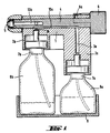
- the bridge shown in Figure 1 has the structure of a simple three-way stopcock: its body 1 forms a plug carrying two twin mouths 2 a and 2 b whose juxtaposed channels 3 a and 3 b have their axes parallel. Its bore receives a key 4 which carries, schematically shown, a spray nozzle 5; here, the key is through and it is its operating button 6 opposite the screwing of the nozzle which serves to retain it.
- each of the mouths 2 a and 2 b fit on the standardized nozzle of the valves 7 a and 7 b , with intake tube, of two aerosol bottles 8 a and 8 b : the bottle 8 a contains the first component and its carrier gas; the bottle 8b contains the second component. So that the bottoms of these bottles can rest on the same flat support despite their difference in height, linked to the fact that the first has a lower capacity here, a different length has been given to the two nozzles.
- the key 4 has a longitudinal transfer groove 10 a and a distribution channel 10 b which opens out through a lateral orifice on another generator; one, in the position shown in the figure, connects the internal orifices of the channels of the two mouths 2 a and 2 b ; if one turns the key by a sufficient angle, it is the other which in turn leads to the only orifice of the mouth 2 b .
- two stops or two cam locking stops for example at 6 a between the skirt of the operating button and the body of the plug.
- the body 1 serves as a pusher and the operator, by pushing it towards the bottles, causes the two valves to open together: firstly, the key 4 being in the position shown, the carrier gas transfers most of it from the contents of the bottle 8 a to the bottle 8 b through the groove 10 a ; after reversing the position of the key, a new pressure on the contrary releases the contents of the bottle 8b to the outside through the channel 10b and the spray nozzle 5.
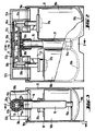
- the bridge used in the case shown in Figures 2 and 3 still forms a three-way valve. It comprises a junction tube 11, which is forced into each of the lateral outlet orifices of two twin heads 12 a and 12 b to connect at right angles to their internal channels 13 a , 13 b , crossing the bore of a sleeve 14 carrying a nozzle such as the nozzle 15 a of the cannula 15.
- Ramps 16 a , 16b keep the axes of heads 12 a and 12 b parallel, side by side.
- valves 17 a and 17 b without intake tube, of two complementary cartridges 18 a and 18 b , the first of which is under pressure, enclosing these cartridges in a casing 19 of which a flange 19 has retained that , complementary, of each of the two heads 12 a , 12 b ; here is an offset in the bottom 19b of the housing 19 which compensates for the difference in length of the two cartridges.
- the valve 17 b is here a metering valve: there are current models, on the bottle 18 b, will lend themselves to the operation described.
- the internal channel of the tube 11 is divided by a central web into two bays which open laterally by two adjacent holes 11 a and 11 b, shown here in the same diametral plane.
- the sleeve 14, which can rotate with gentle friction on the tube 11, carries two internal recesses one, 20 a , longitudinal, capable of bringing the two orifices into communication, the other, 20 b , in L or oblique transversely in rear of the plane of the figure, capable of connecting the orifice 11 b to that of the cannula 15 b 15.
- the cannula disappears in a clearance 21 made between the two cartridges on the side of the housing 19; the recess 20 a then opens a passage between the two valves 17 a and 17 b .
- the valve 17 b is connected to the 'outside.
- the sleeve could also, not without drawbacks, it is true for sealing, be sliding.
- the movable member if necessary returned by a spring, could even be a pusher with an axis parallel to those of the bottles: acting outside of it the operator would cause the transfer; then, pushing it in, it would put the device in the spraying position.
- a tamper-evident belt could be placed on the sleeve, or even between the bridge and the case, provided that the latter is modified to allow the two cartridges to be introduced from the bottom.
Landscapes
- Engineering & Computer Science (AREA)
- Mechanical Engineering (AREA)
- Chemical & Material Sciences (AREA)
- Dispersion Chemistry (AREA)
- Containers And Packaging Bodies Having A Special Means To Remove Contents (AREA)
- Vacuum Packaging (AREA)
- Food-Manufacturing Devices (AREA)
- Disintegrating Or Milling (AREA)
- Basic Packing Technique (AREA)
- Vaporization, Distillation, Condensation, Sublimation, And Cold Traps (AREA)
Description
- Diverses préparations chimiques doivent être élaborées aussi tard que possible avant leur emploi car leurs propriétés s'altèrent progressivement sous l'effet de phénomènes physiques ou chimiques variés, séchage, oxydation, réactions mutuelles, polymérisation... Ce peut être le cas de colles ou tous autres produits à conservation limitée, et en particulier des médicaments dits extemporanés.
- Pour obtenir le mélange intime de leurs éléments, le plus commode, lorsque c'est possible, est de répartir ces derniers en deux composants dont l'un sera liquide et pourra en particulier comprendre un solvant, l'autre pouvant alors se présenter sous des formes diverses, au besoin en phase solide mais souvent dispersée, c'est-à-dire en poudre.
- Le brevet US-A-3608782 propose ainsi de placer les deux composants dans deux tubes souples enfermés dans un boîtier possédant deux compartiments jumeaux de mise sous pression externe dont le premier seul au départ se trouve empli d'un gaz vecteur. Une tête vient s'enfoncer sur ce boîtier, équipée de trois trocards dont les deux premiers, reliés entre eux pour créer un pont, perforent alors deux opercules pour permettre le transfert du premier composant du premier tube vers le second, le troisième venant mettre à l'air libre le second compartiment; puis elle est enlevée et réenfoncée dans une position différente pour mettre sous pression le second compartiment en servant de pont entre lui et le premier tandis que le troisième trocard met à l'air libre le tube correspondant pour permettre l'expulsion du produit. Les opercules sont censés se refermer lorsqu'on enlève la tête.
- Cette solution paraît compliquée, peu commode et incertaine.
- Il est connu d'autre part de fournir divers produits, parfums, insecticides ou autres, sous forme d'aérosols obtenus par détente d'un gaz ou d'un liquide support, azote, butane, hydrocarbure fluoré... qui permet de les délivrer, même à faibles doses, en pulvérisation très fine; ils sont alors commercialisés en bombes ou flacons dits "aérosols", équipés de valves normalisées, généralement miniatures: leur clapet possède une tige de commande tubulaire qui sert de gicleur d'évacuation, et recevra une tête à poussoir de structure variable, qui portera usuellement la buse de pulvérisation voulue. C'est précisément le cas de divers médicaments, le plus souvent destinés au traitement des voies respiratoires, qu'elles soient bucco-pharyngées ou pulmonaires.
- L'invention a pour objet de fournir un conditionnement apte au stockage et au transport puis au mélange des composants de produits évolutifs, et à la distribution de ces derniers, ce conditionnement permettant notamment de présenter sous une forme commode des médicaments à préparation extemporanée.
- Le conditionnement en question sera essentiellement constitué d'un ensemble de deux récipients rigides fermés par des valves "aérosol" et d'un pont de raccordement capable de relier rigidement et de façon étanche leurs deux gicleurs.
- L'un des récipients renfermera, en milieu liquide, sous une pression gazeuse interne suffisamment élevée, le premier composant, mis par exemple en solution avec le gaz vecteur; l'autre renfermera le second composant, sous une pression gazeuse interne faible d'un gaz inerte, au besoin sous un certain vide. Le pont constituera un robinet "à trois voies", l'une d'entrée vers le premier récipient, ouverte par l'organe mobile de ce robinet lors du transfert mais ensuite neutralisée, la deuxième vers le second récipient, permanente sous réserve de l'ouverture de la valve de celui-ci, la troisième de sortie vers l'extérieur,ouverte par l'organe mobile lors de la seule distribution du produit final.
- L'utilisation devant se faire en deux temps, l'un de mélange, le suivant de distribution, le pont permettra d'abord de mettre les deux récipients en communication en pressant simultanément sur les deux valves ce qui provoquera le transfert du premier composant mêlé à une partie du gaz vecteur vers le second récipient avec brassage jusqu'à égalisation des pressions; puis, ouvrant une voie vers l'extérieur, on sera à même, au besoin après un certain temps d'attente voire de stockage, d'expulser à partir de ce récipient, selon son mode de fonctionnement normal, le produit de mélange ou de réaction obtenu, pour en permettre l'utilisation finale.
- Pour éviter qu'une erreur de manipulation ne provoque une mauvaise utilisation, il vaut mieux employer deux récipients semblables, placés côte à côte. Utilement, une dissymétrie externe, au moins visuelle mais de préférence structurelle, évitera toute erreur à l'assemblage.
- D'autres caractéristiques et avantages ressortiront de la description détaillée de deux exemples, donnée ci-dessous en référence aux dessins, qui montrent ces conditionnements avec:
- ― figure 1: une coupe longitudinale d'un conditionnement avec pont à trois voies,
- ― figure 2: une coupe d'un conditionnement analogue avec pont démontable,
- ― figure 3: une coupe transversale de ce conditionnement, selon 3-3 de la figure 2.
- Le pont représenté sur la figure 1 a la structure d'un simple robinet à trois voies: son corps 1 forme un boisseau porteur de deux bouches jumelles 2a et 2b dont les canaux juxtaposés 3a et 3b ont leurs axes parallèles. Son alésage reçoit une clef 4 qui porte, schématiquement représentée, une buse de pulvérisation 5; ici, la clef est traversante et c'est son bouton de manoeuvre 6 à l'opposé du vissage de la buse qui sert à la retenir.
- Les sièges de chacune des bouches 2a et 2b s'adaptent sur le gicleur normalisé des valves 7a et 7b, à tube de prise, de deux flacons pour aérosols 8a et 8b: le flacon 8a renferme le premier composant et son gaz vecteur; le flacon 8b renferme le second composant. Pour que les fonds de ces flacons puissent reposer sur un même appui plan en dépit de leur différence de hauteur, liée au fait que le premier possède ici une moindre capacité, une longueur différente a été donnée aux deux embouts.
- La clef 4 possède une saignée longitudinale de transfert 10a et un canal de distribution 10b qui débouche par un orifice latéral sur une autre génératrice; l'une, dans la position représentée sur la figure, relie les orifices internes des canaux des deux bouches 2a et 2b; si l'on tourne la clef d'un angle suffisant, c'est l'autre qui débouche à son tour sur le seul orifice de la bouche 2b. Pour repérer ces deux positions, on peut prévoir deux butées ou deux crans d'arrêt à effet de cames, par exemple en 6a entre la jupe du bouton de manoeuvre et le corps du boisseau.
- Le corps 1 sert de poussoir et l'opérateur, en l'enfonçant vers les flacons, fait s'ouvrir ensemble les deux valves: dans un premier temps, la clef 4 se trouvant dans la position représentée, le gaz vecteur transfère la majeure partie du contenu du flacon 8a vers le flacon 8b à travers la saignée 10a; après inversion de la position de la clef, une nouvelle pression libère au contraire le contenu du flacon 8b vers l'extérieur à travers le canal 10b et la buse de pulvérisation 5.
- De nombreuses variantes sont également possibles, utilisant par exemple une douille tournante montée, en rotation ou même à mouvement hélicoïdal pour obtenir une meilleure étanchéité, aussi bien dans l'axe du raccordement que sur celui de la valve 7b du second flacon.
- Le pont utilisé dans le cas que représentent les figures 2 et 3 forme encore un robinet à trois voies. Il comprend un tube de jonction 11, qui s'emboîte à force sur chacun des orifices de sortie latéraux de deux têtes jumelles 12a et 12b pour se raccorder à angle droit à leurs canaux internes 13a, 13b, en traversant l'alésage d'un manchon 14 porteur d'une buse telle que la buse 15a de la canule 15. Des rampes 16a, 16b maintiennent parallèles, côte à côte, les axes des têtes 12a et 12b. Sur leurs sièges s'adaptent les valves 17a et 17b, sans tube de prise, de deux cartouches complémentaires 18a et 18b, dont la première est sous pression, enfermant ces cartouches dans un boîtier 19 dont un rebord 19a retient celui, complémentaire, de chacune des deux têtes 12a, 12b; c'est ici un décalage dans le fond 19b du boîtier 19 qui compense la différence de longueur des deux cartouches.
- La valve 17b est ici une valve doseuse: il en existe des modèles courants qui, sur le flacon 18b, se préteront au fonctionnement décrit.
- Le canal interne du tube 11 est divisé par un voile médian en deux biefs qui débouchent latéralement par deux orifices voisins 11a et 11b, représentés ici dans le même plan diamétral. Le manchon 14, qui peut tourner à frottement doux sur le tube 11, porte deux évidements internes l'un, 20a, longitudinal, capable de mettre en communication les deux orifices, l'autre, 20b, en L ou oblique transversalement en arrière du plan de figure, capable de relier l'orifice 11b à celui 15b de la canule 15.
- Au repos, déportée ici transversalement par rapport à l'axe du tube, la canule s'efface dans un dégagement 21 pratiqué entre les deux cartouches sur le côté du boîtier 19; l'évidement 20a ouvre alors un passage entre les deux valves 17a et 17b. Par rotation il est possible de la redresser, par exemple jusqu'à mise en butée sur l'une des rampes 22a, 22b: seule alors, par le jeu de l'évidement 20b, la valve 17b est reliée à l'extérieur.
- Une dissymétrie de la canule et de son logement suffit à éviter toute erreur au montage ou en service; si au contraire le manchon 14 avait l'apparence de la symétrie, il serait bon de prolonger l'évidement 20b en 20c vers l'avant du plan de figure (trait mixte), sans que ce prolongement ait un rôle actif immédiat, pour obtenir une structure interne effectivement symétrique par rapport à un axe vertical, ce qui rendrait le montage indifférent.
- On notera que le manchon pourrait aussi, non sans inconvénients il est vrai pour l'étanchéité, être coulissant. L'organe mobile, au besoin renvoyé par un ressort, pourrait même être un poussoir d'axe parallèle à ceux des flacons: agissant en dehors de lui l'opérateur provoquerait le transfert; ensuite, l'enfonçant, il mettrait le dispositif en position de pulvérisation.
- Enfin une ceinture inviolable pourrait être placée sur le manchon, voire entre le pont et le boîtier à condition de modifier ce dernier pour permettre d'introduire les deux cartouches par le fond.
Claims (7)
Priority Applications (1)
| Application Number | Priority Date | Filing Date | Title |
|---|---|---|---|
| AT88400212T ATE66892T1 (de) | 1987-02-09 | 1988-01-29 | Mischer-verteiler-verpackung. |
Applications Claiming Priority (2)
| Application Number | Priority Date | Filing Date | Title |
|---|---|---|---|
| FR8701519 | 1987-02-09 | ||
| FR8701519A FR2610602B1 (fr) | 1987-02-09 | 1987-02-09 | Conditionnement melangeur distributeur |
Publications (2)
| Publication Number | Publication Date |
|---|---|
| EP0279727A1 EP0279727A1 (fr) | 1988-08-24 |
| EP0279727B1 true EP0279727B1 (fr) | 1991-09-04 |
Family
ID=9347690
Family Applications (1)
| Application Number | Title | Priority Date | Filing Date |
|---|---|---|---|
| EP19880400212 Expired - Lifetime EP0279727B1 (fr) | 1987-02-09 | 1988-01-29 | Conditionnement mélangeur distributeur |
Country Status (6)
| Country | Link |
|---|---|
| US (1) | US4969579A (fr) |
| EP (1) | EP0279727B1 (fr) |
| AT (1) | ATE66892T1 (fr) |
| DE (1) | DE3864535D1 (fr) |
| ES (1) | ES2026660T3 (fr) |
| FR (1) | FR2610602B1 (fr) |
Cited By (1)
| Publication number | Priority date | Publication date | Assignee | Title |
|---|---|---|---|---|
| WO2002076373A1 (fr) * | 2001-03-27 | 2002-10-03 | Allen Beaumont Hall | Recipient distributeur a chambre double avec clapet pivotant |
Families Citing this family (43)
| Publication number | Priority date | Publication date | Assignee | Title |
|---|---|---|---|---|
| US5150822A (en) * | 1989-10-27 | 1992-09-29 | The Wellcome Foundation Limited | Mixing head for dispensing an actine ingredient |
| FR2662672B1 (fr) * | 1990-05-31 | 1992-08-21 | Aerosols & Bouchage | Dispensateur de melange. |
| DE4102506C2 (de) * | 1991-01-29 | 1999-11-25 | Pfeiffer Erich Gmbh & Co Kg | Austragvorrichtung für Medien |
| USD343351S (en) | 1991-02-08 | 1994-01-18 | Company Number 42 Limited | Container |
| US8028864B2 (en) | 1992-02-24 | 2011-10-04 | Homax Products, Inc. | Actuator systems and methods for aerosol wall texturing |
| US6883688B1 (en) | 1992-02-24 | 2005-04-26 | Homax Products, Inc. | Aerosol spray texturing systems and methods |
| US7278590B1 (en) | 1992-02-24 | 2007-10-09 | Homax Products, Inc. | Systems and methods for applying texture material to ceiling surfaces |
| US6152335A (en) | 1993-03-12 | 2000-11-28 | Homax Products, Inc. | Aerosol spray texture apparatus for a particulate containing material |
| US5964377A (en) * | 1997-10-14 | 1999-10-12 | S. C. Johnson & Son, Inc. | Manually operable pump for mixing and dispensing primary and secondary fluids |
| US20040086453A1 (en) * | 2001-01-22 | 2004-05-06 | Howes Randolph M. | Compositions, methods, apparatuses, and systems for singlet oxygen delivery |
| US6604655B1 (en) * | 2002-02-27 | 2003-08-12 | Jung Kuo Enterprise Co., Ltd. | Combination of liquid containers with caps depressible for ejecting the contents |
| US7063236B2 (en) * | 2002-03-14 | 2006-06-20 | Homax Products, Inc. | Aerosol systems and methods for mixing and dispensing two-part materials |
| CA2422244A1 (fr) * | 2002-03-14 | 2003-09-14 | Homax Products, Inc. | Systemes et methodes a aerosol pour le melange et la distribution de materiaux a deux elements |
| US7906473B2 (en) * | 2002-09-13 | 2011-03-15 | Bissell Homecare, Inc. | Manual spray cleaner |
| US6910608B2 (en) * | 2002-11-12 | 2005-06-28 | Homax Products, Inc. | Storage systems and methods for aerosol accessories |
| US7500621B2 (en) | 2003-04-10 | 2009-03-10 | Homax Products, Inc. | Systems and methods for securing aerosol systems |
| US20050161531A1 (en) | 2004-01-28 | 2005-07-28 | Greer Lester R.Jr. | Texture material for covering a repaired portion of a textured surface |
| US7677420B1 (en) | 2004-07-02 | 2010-03-16 | Homax Products, Inc. | Aerosol spray texture apparatus for a particulate containing material |
| US7487893B1 (en) | 2004-10-08 | 2009-02-10 | Homax Products, Inc. | Aerosol systems and methods for dispensing texture material |
| FR2894790B1 (fr) * | 2005-12-15 | 2008-02-15 | Oreal | Dispositif de conditionnement et de distribution, notamment pour reservoir a faible contenance |
| US8344056B1 (en) | 2007-04-04 | 2013-01-01 | Homax Products, Inc. | Aerosol dispensing systems, methods, and compositions for repairing interior structure surfaces |
| US8580349B1 (en) | 2007-04-05 | 2013-11-12 | Homax Products, Inc. | Pigmented spray texture material compositions, systems, and methods |
| US9382060B1 (en) | 2007-04-05 | 2016-07-05 | Homax Products, Inc. | Spray texture material compositions, systems, and methods with accelerated dry times |
| RU2508133C2 (ru) * | 2008-04-21 | 2014-02-27 | МакНЕЙЛ-ППС, ИНК. | Устройство доставки для местного применения, содержащее две аэрозольные камеры |
| US8255089B2 (en) | 2010-05-28 | 2012-08-28 | S.C. Johnson & Son, Inc. | Multiple volatile material dispensing device and operating methodologies therefore |
| US8967412B2 (en) | 2010-08-03 | 2015-03-03 | James A Loging | Drinking cup with lid and flow control element |
| US9248457B2 (en) | 2011-07-29 | 2016-02-02 | Homax Products, Inc. | Systems and methods for dispensing texture material using dual flow adjustment |
| US9156042B2 (en) | 2011-07-29 | 2015-10-13 | Homax Products, Inc. | Systems and methods for dispensing texture material using dual flow adjustment |
| DE102012009570A1 (de) * | 2012-05-09 | 2013-11-14 | Naum Goldstein | Komposition für nasale Anwendung |
| US9156602B1 (en) | 2012-05-17 | 2015-10-13 | Homax Products, Inc. | Actuators for dispensers for texture material |
| US9435120B2 (en) | 2013-03-13 | 2016-09-06 | Homax Products, Inc. | Acoustic ceiling popcorn texture materials, systems, and methods |
| CA2859537C (fr) | 2013-08-19 | 2019-10-29 | Homax Products, Inc. | Materiaux, systemes et procedes de texture pour plafond |
| USD787326S1 (en) | 2014-12-09 | 2017-05-23 | Ppg Architectural Finishes, Inc. | Cap with actuator |
| FR3032353B1 (fr) | 2015-02-06 | 2017-03-10 | Jacques Seguin | Composition pharmaceutique et dispositif pour le traitement de la douleur |
| JP2016166021A (ja) * | 2015-03-09 | 2016-09-15 | 株式会社中央ハイテック | エアゾール容器用噴射ボタン及びその製造方法 |
| US10746353B2 (en) * | 2015-07-27 | 2020-08-18 | First Power Group, LLC | Remotely controlled material delivery system |
| US9579676B1 (en) * | 2015-09-09 | 2017-02-28 | The Procter & Gamble Company | Dispensers for microcapsules |
| USD832546S1 (en) | 2017-05-16 | 2018-10-30 | Garland Industries, Inc. | Paint can insert |
| USD832545S1 (en) | 2017-05-16 | 2018-10-30 | Garland Industries, Inc. | Paint can insert |
| US20230380414A1 (en) * | 2020-10-12 | 2023-11-30 | Boundless Science, Llc | Systems, devices and methods for delivering aerosolized fluorocarbons |
| USD1049851S1 (en) | 2021-08-25 | 2024-11-05 | Chargrinovations, LLC | Paint can cap |
| JP7825928B2 (ja) * | 2022-09-29 | 2026-03-09 | 株式会社吉野工業所 | 吐出容器 |
| WO2025075897A1 (fr) * | 2023-10-02 | 2025-04-10 | Zynon Technologies, Llc | Réceptacle de stockage et de distribution de liquides |
Family Cites Families (14)
| Publication number | Priority date | Publication date | Assignee | Title |
|---|---|---|---|---|
| US1514944A (en) * | 1922-06-07 | 1924-11-11 | Swingspout Measure Company | Swingspout pouring device for containers |
| BE637604A (fr) * | 1962-09-27 | |||
| BE639762A (fr) * | 1962-11-16 | |||
| US3181737A (en) * | 1963-09-30 | 1965-05-04 | R H Macy & Co Inc | Method of storing, combining and applying two-part polymer mixtures |
| US3343718A (en) * | 1965-04-06 | 1967-09-26 | Capitol Packaging Co | Method of forming and dispensing aerosol dispensible polymerizable compositions |
| FR1591250A (fr) * | 1968-11-05 | 1970-04-27 | ||
| DE2001177A1 (de) * | 1970-01-13 | 1971-07-22 | Lothar Sachsse | Fluessigkeitszerstaeuber |
| FR2105332A5 (fr) * | 1970-09-01 | 1972-04-28 | Oreal | |
| DE2631550C3 (de) * | 1976-07-14 | 1981-02-12 | Regina 5241 Birken Hauptmann Geb. Gerhardus | Spritzpistole mit Treibgasantrieb |
| US4469252A (en) * | 1981-04-10 | 1984-09-04 | Aerosol Service Ag | Two-compartment package |
| DE3237263A1 (de) * | 1982-10-08 | 1984-04-12 | Deutsche Präzisions-Ventil GmbH, 6234 Hattersheim | Ventilsystem fuer druckgaspackung mit zweikomponentenprodukt |
| FR2545792B1 (fr) * | 1983-05-13 | 1985-09-06 | Avitex | Emballage du type aerosol bicameral |
| DE3405065A1 (de) * | 1984-02-13 | 1985-08-22 | F.P.D. Future Patents Development Co. S.A., Luxemburg/Luxembourg | Vorrichtung zum herstellen und verspruehen einer aus wenigstens zwei komponenten, z. b. fluessigkeiten, und einem treibgas bestehenden mischung |
| DE8405841U1 (de) * | 1984-02-25 | 1987-04-16 | Hoernecke, Carl, 7141 Oberstenfeld | Reizstoffsprühgerät |
-
1987
- 1987-02-09 FR FR8701519A patent/FR2610602B1/fr not_active Expired
-
1988
- 1988-01-29 EP EP19880400212 patent/EP0279727B1/fr not_active Expired - Lifetime
- 1988-01-29 DE DE8888400212T patent/DE3864535D1/de not_active Expired - Lifetime
- 1988-01-29 ES ES198888400212T patent/ES2026660T3/es not_active Expired - Lifetime
- 1988-01-29 AT AT88400212T patent/ATE66892T1/de not_active IP Right Cessation
-
1989
- 1989-09-25 US US07/412,620 patent/US4969579A/en not_active Expired - Fee Related
Cited By (1)
| Publication number | Priority date | Publication date | Assignee | Title |
|---|---|---|---|---|
| WO2002076373A1 (fr) * | 2001-03-27 | 2002-10-03 | Allen Beaumont Hall | Recipient distributeur a chambre double avec clapet pivotant |
Also Published As
| Publication number | Publication date |
|---|---|
| DE3864535D1 (de) | 1991-10-10 |
| FR2610602B1 (fr) | 1989-07-21 |
| FR2610602A1 (fr) | 1988-08-12 |
| US4969579A (en) | 1990-11-13 |
| ES2026660T3 (es) | 1992-05-01 |
| ATE66892T1 (de) | 1991-09-15 |
| EP0279727A1 (fr) | 1988-08-24 |
Similar Documents
| Publication | Publication Date | Title |
|---|---|---|
| EP0279727B1 (fr) | Conditionnement mélangeur distributeur | |
| EP1167231B1 (fr) | Ensemble pour le mélange extemporané de deux produits | |
| EP0461010B1 (fr) | Dispensateur de mélange | |
| EP1132318B1 (fr) | Distributeur pour la distribution sélective d'au moins deux composants, et procédé pour sa mise en oeuvre | |
| CA2245988C (fr) | Ensemble de conditionnement et de distribution bi-produits | |
| EP0670275B1 (fr) | Dispositif de distribution à fermeture étanche pour un récipient pressurisé ou à pompe | |
| EP0453555B1 (fr) | Flacon de stockage contenant un composant d'une solution medicamenteuse | |
| WO2000045963A1 (fr) | Distributeur de produits chimiquement instables | |
| EP0589029B1 (fr) | Procede pour realiser un melange extemporane d'au moins deux composants, liquides ou pateux, et bidon pressurise pour mettre en oeuvre un tel procede | |
| US5012978A (en) | Aerosol dispenser and method | |
| CA2130122A1 (fr) | Dispositif pour la preparation d'une solution, d'une suspension ou d'une emulsion d'une substance medicinale | |
| CA2429674A1 (fr) | Production de micromousse therapeutique | |
| EP1744717A1 (fr) | Seringue pour interventions medicales et necessaire de reconstitution de substances extemporanees comportant une telle seringue | |
| CA2006582A1 (fr) | Flacon de stockage et de transfert concu pour stocker deux composants dune substance medicamenteuse | |
| EP0786419B1 (fr) | Flacon doseur | |
| FR2719789A1 (fr) | Dispositif de distribution d'un produit en mélange avec un fluide, ensemble de distribution comprenant un tel dispositif. | |
| EP1033323B1 (fr) | Conditionnement pour effectuer le mélange d'un produit à plusieurs composants | |
| EP2024256A1 (fr) | Valve à deux voies | |
| EP0752966B1 (fr) | Mecanisme de commande a poussoirs lateraux pour la distribution d'un produit contenu dans un recipient | |
| EP1124646B1 (fr) | Reservoir pourvu d'un dispositif de fermeture et de remplissage et/ou pulverisateur de produit fluide comportant un tel reservoir | |
| EP0905049B1 (fr) | Conditionnement pour un produit à trois composants | |
| EP0296950B1 (fr) | Pulvérisateur de produits stériles, notamment de solutions aseptiques pour traitements médicaux et chirurgicaux | |
| FR2663304A1 (fr) | Conditionnement compartimente de securite. | |
| EP0814914B1 (fr) | Dispositif de stockage et de distribution d'un produit, tel un produit cosmetique ou un parfum | |
| EP0562943A1 (fr) | Conditionnement double |
Legal Events
| Date | Code | Title | Description |
|---|---|---|---|
| PUAI | Public reference made under article 153(3) epc to a published international application that has entered the european phase |
Free format text: ORIGINAL CODE: 0009012 |
|
| AK | Designated contracting states |
Kind code of ref document: A1 Designated state(s): AT BE CH DE ES FR GB GR IT LI LU NL SE |
|
| 17P | Request for examination filed |
Effective date: 19881216 |
|
| RAP3 | Party data changed (applicant data changed or rights of an application transferred) |
Owner name: SOFAB SOCIETE FRANCAISE D'AEROSOLS ET DE BOUCHAGE |
|
| 17Q | First examination report despatched |
Effective date: 19900920 |
|
| GRAA | (expected) grant |
Free format text: ORIGINAL CODE: 0009210 |
|
| AK | Designated contracting states |
Kind code of ref document: B1 Designated state(s): AT BE CH DE ES FR GB GR IT LI LU NL SE |
|
| PG25 | Lapsed in a contracting state [announced via postgrant information from national office to epo] |
Ref country code: GR Free format text: LAPSE BECAUSE OF FAILURE TO SUBMIT A TRANSLATION OF THE DESCRIPTION OR TO PAY THE FEE WITHIN THE PRESCRIBED TIME-LIMIT Effective date: 19910904 |
|
| REF | Corresponds to: |
Ref document number: 66892 Country of ref document: AT Date of ref document: 19910915 Kind code of ref document: T |
|
| RAP2 | Party data changed (patent owner data changed or rights of a patent transferred) |
Owner name: SOCIETE FRANCAISE D'AEROSOLS ET DE BOUCHAGE |
|
| REF | Corresponds to: |
Ref document number: 3864535 Country of ref document: DE Date of ref document: 19911010 |
|
| ITF | It: translation for a ep patent filed | ||
| RAP4 | Party data changed (patent owner data changed or rights of a patent transferred) |
Owner name: SOCIETE FRANCAISE D'AEROSOLS ET DE BOUCHAGE |
|
| REG | Reference to a national code |
Ref country code: CH Ref legal event code: PUE Owner name: SOCIETE FRANCAISE D'AEROSOLS ET DE BOUCHAGE |
|
| GBT | Gb: translation of ep patent filed (gb section 77(6)(a)/1977) | ||
| BECN | Be: change of holder's name |
Effective date: 19910904 |
|
| PG25 | Lapsed in a contracting state [announced via postgrant information from national office to epo] |
Ref country code: LU Free format text: LAPSE BECAUSE OF NON-PAYMENT OF DUE FEES Effective date: 19920131 |
|
| REG | Reference to a national code |
Ref country code: ES Ref legal event code: FG2A Ref document number: 2026660 Country of ref document: ES Kind code of ref document: T3 |
|
| PLBE | No opposition filed within time limit |
Free format text: ORIGINAL CODE: 0009261 |
|
| STAA | Information on the status of an ep patent application or granted ep patent |
Free format text: STATUS: NO OPPOSITION FILED WITHIN TIME LIMIT |
|
| 26N | No opposition filed | ||
| EAL | Se: european patent in force in sweden |
Ref document number: 88400212.2 |
|
| REG | Reference to a national code |
Ref country code: GB Ref legal event code: IF02 |
|
| PGFP | Annual fee paid to national office [announced via postgrant information from national office to epo] |
Ref country code: NL Payment date: 20021217 Year of fee payment: 16 |
|
| PGFP | Annual fee paid to national office [announced via postgrant information from national office to epo] |
Ref country code: SE Payment date: 20021218 Year of fee payment: 16 Ref country code: AT Payment date: 20021218 Year of fee payment: 16 |
|
| PGFP | Annual fee paid to national office [announced via postgrant information from national office to epo] |
Ref country code: DE Payment date: 20030108 Year of fee payment: 16 |
|
| PGFP | Annual fee paid to national office [announced via postgrant information from national office to epo] |
Ref country code: CH Payment date: 20030113 Year of fee payment: 16 |
|
| PGFP | Annual fee paid to national office [announced via postgrant information from national office to epo] |
Ref country code: ES Payment date: 20030117 Year of fee payment: 16 |
|
| PGFP | Annual fee paid to national office [announced via postgrant information from national office to epo] |
Ref country code: GB Payment date: 20030121 Year of fee payment: 16 |
|
| PGFP | Annual fee paid to national office [announced via postgrant information from national office to epo] |
Ref country code: BE Payment date: 20030213 Year of fee payment: 16 |
|
| PGFP | Annual fee paid to national office [announced via postgrant information from national office to epo] |
Ref country code: FR Payment date: 20040116 Year of fee payment: 17 |
|
| PG25 | Lapsed in a contracting state [announced via postgrant information from national office to epo] |
Ref country code: GB Free format text: LAPSE BECAUSE OF NON-PAYMENT OF DUE FEES Effective date: 20040129 Ref country code: AT Free format text: LAPSE BECAUSE OF NON-PAYMENT OF DUE FEES Effective date: 20040129 |
|
| PG25 | Lapsed in a contracting state [announced via postgrant information from national office to epo] |
Ref country code: SE Free format text: LAPSE BECAUSE OF NON-PAYMENT OF DUE FEES Effective date: 20040130 Ref country code: ES Free format text: LAPSE BECAUSE OF NON-PAYMENT OF DUE FEES Effective date: 20040130 |
|
| PG25 | Lapsed in a contracting state [announced via postgrant information from national office to epo] |
Ref country code: LI Free format text: LAPSE BECAUSE OF NON-PAYMENT OF DUE FEES Effective date: 20040131 Ref country code: CH Free format text: LAPSE BECAUSE OF NON-PAYMENT OF DUE FEES Effective date: 20040131 Ref country code: BE Free format text: LAPSE BECAUSE OF NON-PAYMENT OF DUE FEES Effective date: 20040131 |
|
| BERE | Be: lapsed |
Owner name: SOC. *FRANCAISE D'AEROSOLS ET DE BOUCHAGE Effective date: 20040131 |
|
| PG25 | Lapsed in a contracting state [announced via postgrant information from national office to epo] |
Ref country code: NL Free format text: LAPSE BECAUSE OF NON-PAYMENT OF DUE FEES Effective date: 20040801 |
|
| PG25 | Lapsed in a contracting state [announced via postgrant information from national office to epo] |
Ref country code: DE Free format text: LAPSE BECAUSE OF NON-PAYMENT OF DUE FEES Effective date: 20040803 |
|
| EUG | Se: european patent has lapsed | ||
| GBPC | Gb: european patent ceased through non-payment of renewal fee |
Effective date: 20040129 |
|
| REG | Reference to a national code |
Ref country code: CH Ref legal event code: PL |
|
| NLV4 | Nl: lapsed or anulled due to non-payment of the annual fee |
Effective date: 20040801 |
|
| PG25 | Lapsed in a contracting state [announced via postgrant information from national office to epo] |
Ref country code: IT Free format text: LAPSE BECAUSE OF NON-PAYMENT OF DUE FEES;WARNING: LAPSES OF ITALIAN PATENTS WITH EFFECTIVE DATE BEFORE 2007 MAY HAVE OCCURRED AT ANY TIME BEFORE 2007. THE CORRECT EFFECTIVE DATE MAY BE DIFFERENT FROM THE ONE RECORDED. Effective date: 20050129 |
|
| REG | Reference to a national code |
Ref country code: ES Ref legal event code: FD2A Effective date: 20040130 |
|
| PG25 | Lapsed in a contracting state [announced via postgrant information from national office to epo] |
Ref country code: FR Free format text: LAPSE BECAUSE OF NON-PAYMENT OF DUE FEES Effective date: 20050930 |
|
| REG | Reference to a national code |
Ref country code: FR Ref legal event code: ST |