EP0278329A1 - Procédé pour la construction de murs et ensemble d'éléments de construction pour réaliser ce procédé - Google Patents
Procédé pour la construction de murs et ensemble d'éléments de construction pour réaliser ce procédé Download PDFInfo
- Publication number
- EP0278329A1 EP0278329A1 EP88101197A EP88101197A EP0278329A1 EP 0278329 A1 EP0278329 A1 EP 0278329A1 EP 88101197 A EP88101197 A EP 88101197A EP 88101197 A EP88101197 A EP 88101197A EP 0278329 A1 EP0278329 A1 EP 0278329A1
- Authority
- EP
- European Patent Office
- Prior art keywords
- stones
- stone
- groove
- chambers
- abutting
- Prior art date
- Legal status (The legal status is an assumption and is not a legal conclusion. Google has not performed a legal analysis and makes no representation as to the accuracy of the status listed.)
- Withdrawn
Links
Images

Classifications
-
- E—FIXED CONSTRUCTIONS
- E04—BUILDING
- E04B—GENERAL BUILDING CONSTRUCTIONS; WALLS, e.g. PARTITIONS; ROOFS; FLOORS; CEILINGS; INSULATION OR OTHER PROTECTION OF BUILDINGS
- E04B2/00—Walls, e.g. partitions, for buildings; Wall construction with regard to insulation; Connections specially adapted to walls
- E04B2/02—Walls, e.g. partitions, for buildings; Wall construction with regard to insulation; Connections specially adapted to walls built-up from layers of building elements
- E04B2/14—Walls having cavities in, but not between, the elements, i.e. each cavity being enclosed by at least four sides forming part of one single element
- E04B2/16—Walls having cavities in, but not between, the elements, i.e. each cavity being enclosed by at least four sides forming part of one single element using elements having specially-designed means for stabilising the position
- E04B2/18—Walls having cavities in, but not between, the elements, i.e. each cavity being enclosed by at least four sides forming part of one single element using elements having specially-designed means for stabilising the position by interlocking of projections or inserts with indentations, e.g. of tongues, grooves, dovetails
-
- E—FIXED CONSTRUCTIONS
- E04—BUILDING
- E04B—GENERAL BUILDING CONSTRUCTIONS; WALLS, e.g. PARTITIONS; ROOFS; FLOORS; CEILINGS; INSULATION OR OTHER PROTECTION OF BUILDINGS
- E04B2/00—Walls, e.g. partitions, for buildings; Wall construction with regard to insulation; Connections specially adapted to walls
- E04B2/02—Walls, e.g. partitions, for buildings; Wall construction with regard to insulation; Connections specially adapted to walls built-up from layers of building elements
- E04B2002/0202—Details of connections
- E04B2002/0204—Non-undercut connections, e.g. tongue and groove connections
- E04B2002/0206—Non-undercut connections, e.g. tongue and groove connections of rectangular shape
Definitions
- the invention is based on a method for pulling up walls from stacked bricks, in the abutting surfaces and bearing surfaces of which a tongue and groove system is formed.
- the invention relates to the raising of walls made of lightweight concrete blocks, such as those which are produced from the naturally occurring raw natural pumice material after the cleaning of organic and inorganic accompanying substances and without the addition of chemical substances.
- Lightweight concrete blocks of this type have become known under the registered trademark "Bisotherm".
- the well-known lightweight concrete blocks with a tongue and groove system in the area of their joint surfaces enable mortar-free butt joints and thus a considerable reduction in mortar consumption as well as a considerably lower workload for masonry compared to the conventional mortaring of butt joints and bed joints.
- the tongue and groove system of these known bricks which is limited to the butt joints, ensures displacement-safe toothing in the butt joint and a full-surface load transmission in the bed joint.
- Height differences of ⁇ 4 mm are permitted for the lightweight concrete blocks provided with air slots or chambers, which is why a layer of mortar in the bed joint, which is usually around 12 mm thick, is required to compensate for tolerances in order to compensate for these height differences (dimensional deviation of the stones in the height direction).
- This lack of constant height is primarily a result of the manufacturing process and can at best be reduced by an unacceptably high technical effort (machining to size of each individual stone, e.g. by milling).
- lightweight concrete blocks provided with air slots or chambers are produced in such a way that molds consisting of metal (steel), into which cores are used, are preferred the air slots or chambers are hung, filled from above with the help of a filling truck.
- the mold filling is supported by vibration, and the filled material is compressed by the pressure applied from above to the filling compound (consisting of aggregate, binder and water) that has been compacted. After the compaction process has ended, the mold can be lifted upwards from the molding which remains on a base until it is sufficiently solidified.
- the height of the finished stone depends on the composition of the filling mass, the degree of vibration and the compaction force, the height differences mentioned are ⁇ 4 mm. It is understood that “height difference” or “height tolerance” is to be understood as the direction in which the filled material has been compressed in the mold or in which the mold has been filled with the filling compound.
- a stone removed from the mold has six surfaces, namely an upper surface, an opposing lower surface, two opposing end faces, which are each arranged between the upper and the lower surface and further two side surfaces which adjoin the upper and lower surfaces and connect the two faces together.
- the disturbing height tolerances occur in the distance between the lower and upper stone surface.
- the four other stone surfaces are determined by the metal mold, so that the stone length and the stone width, apart from the wear of the mold, can be considered practically constant.
- the air slots do not usually penetrate the stones from the top surface to the bottom surface, but end shortly before the bottom surface of the stone. To block these stones, they are moved upwards with the closed surface (the lower surface in the form) so that the mortar does not run into the slots or chambers.
- the invention has for its object to provide a method for lifting walls from stacked bricks so that it is possible to lay the stones with an extremely low, practically constant height tolerance of about ⁇ 1 mm, so that instead of mortar in the bed joint an adhesive can be used or even bricked up entirely without adhesive and without mortar, without the stones having to be processed in an additional operation, for example by milling, in order to reduce the height tolerance which arises during production.
- the invention has the task of creating a kit of bricks, which are designed so that despite the absence of mortar and possibly an adhesive in the butt joints and in the bed joints a non-displaceable connection of adjacent stones and stones lying on top of each other and a force-transmitting connection of the Ensure stones or stone layers so that compressive and shear stresses can be absorbed.
- This object is achieved according to the invention in a method for lifting walls from stones provided with air slots (chambers) in that the stones are positively locked on four of their surfaces and in that the stones pivot in a vertical plane to their production position by 90 ° Position in which the slots run substantially horizontally from abutting surface to abutting surface.
- This high dimensional accuracy of the staggered stones in the vertical direction is the result of the bricking position rotated by 90 ° with respect to the production position.
- This swiveling by 90 ° means that the surfaces of the stone affected by the dimensional fluctuations, i.e. the so-called upper surface and the so-called lower surface, now serve as abutting surfaces (ie after being rotated by 90 °), whereas the original ones obtained by the metal mold true to size Side surfaces after swiveling determine the height of the brick and the original end surfaces serve as storage surfaces after swiveling.
- a tolerance compensation layer in the form of a mortar layer has become superfluous, so that the layer according to the invention Staggered stones can be processed with the help of an adhesive or entirely without a connecting means in the bed joints and butt joints.
- stones are used which each have a spring in one of their abutment surfaces and in one of their bearing surfaces and each have a groove which is complementary to the springs in the other abutment surface and in the other bearing surface.
- tongue and groove are designed to be complementary to one another, adjacent stones can be positively connected to one another by tongue and groove, and stones lying on top of one another are also connected to one another in a form-fitting manner by a tongue and groove system.
- a uniform spring direction is selected for each stone within a stone layer and that the spring direction of the spring is changed from stone layer to stone layer.
- a lower stone layer can be laid so that the springs are provided in the left-hand joint surface and in the upper bearing surface.
- an opposite orientation is then selected so that the right-hand abutting surfaces and (unchanged) the upper bearing surfaces have the tongue, whereas the left-hand abutting surfaces have the groove.
- the object on which the invention is based is achieved by stones provided with louvers (chambers) which have a groove in one of their bearing surfaces and a complementarily designed tongue in the opposite bearing surface and a groove in one of their abutting surfaces and a complementary one in the other abutting surface have designed spring, the grooves and tongues in the abutting surface area of adjacent stones and the grooves and tongues of stones lying one on top of the other interlock. If the stones have been laid according to the invention, then their air slots or chambers run parallel to the bed joints, that is to say perpendicular to the course of the slots or chambers in the production position.
- the kit consisting of the stones designed according to the invention enables walls to be erected without the need for mortar, since neither the butt joints nor the bed joints need to be mortared.
- a thin layer of adhesive is sufficient even for the highest demands.
- the kit according to the invention additionally comprises first supplementary stones for achieving smooth surfaces in the case of horizontal wall closures, for example parapets, for pillar bandages and corner bandages and for door or window reveals, and second supplementary stones for window or door stops.
- the first and second supplementary stones have grooves matched to the springs of the stones provided with air slots (chambers).
- the walls raised according to the invention ensure a high resistance to shear forces and, thanks to their large load transfer in the bearing joints, a high masonry tension.
- the masonry according to the invention has surprisingly high thermal insulation.
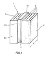
- Fig. 1 shows a cuboid brick 1 in its production position, that is with the top surface in essentially vertically downwardly extending air slots or chambers 3.
- the stone surface having the slots 3 is designated by the reference symbol A.
- the area A and an adjacent area B are provided with a spring-like element, the spring section in the area of the area A being designated by the reference number 2a and the spring section in the area of the area B having the reference number 2b is.
- the spring 2a runs parallel to the width extension of the slots 3 in the surface A and runs essentially in the central axis of the stone surface A.
- the spring 2a runs parallel to the shorter edge of the surface A.
- the spring 2b runs in the central axis of the stone surface B, wherein in the illustrated embodiment the area B is one of the two large cuboid areas.
- the area opposite the surface A which is not visible in FIG.
- a groove 4 corresponding to the dimension 2a is formed and in the surface opposite the surface B, which is not visible in FIG. 1, a groove corresponding to the dimension 2b is formed.
- the surface (not shown) opposite surface A in the case of air slots 3 which penetrate stone 1 completely looks just like surface A. In the case of non-continuous slots 3, the surface opposite surface A has no slots or chambers. Since, within the scope of the invention, a mortar or adhesive application, if provided, is not applied to the surface opposite surface A, but because of the pivoting through 90 ° from the production position, only to surface B or to the surface opposite surface B, can be used within the scope of the invention without further stones with continuous louvers.
- the springs 2a and 2b complement each other in pairs with the associated grooves for a true positive fit when two stones of the type shown in FIG. 1 are placed one on top of the other with their bearing surfaces or with their abutting surfaces.
- the bricks according to the invention correspond to the usual grid dimensions and have, for example, a length of 30 cm, a height of 25 cm and a thickness (wall thickness) of 24; 30 and 36.5 cm.
- the stone shown in Fig. 1 is a lightweight concrete block for a 30 cm thick wall with an edge length of 300 mm for the two long sides of the area A and an edge length of 250 mm for the two shorter sides of the area A.
- the spring elements 2a and 2b have a width of 30 to 50 mm, and in the case of grooves with a frustoconical cross section, the angle of inclination of the two spring side walls is in each case approximately 45 °.
- the spring height in the illustrated embodiment is approximately 15 mm.
- the grooves in the two surfaces not visible in Fig. 1 are dimensioned according to the spring dimensions given above, so that both the bearing surfaces and the abutment surfaces of the stone (see Fig. 2) with elements complementing each other to form a true positive fit in the manner of a groove and spring are provided.
- each of the slots 3 has a width of approximately 7.5 mm with different slot lengths of 50 and 110 mm.
- Three rows of slots 3 are provided on each side of the spring 2a, the distance from slot to slot being 30 to 35 mm.
- the length of the two long sides of the area A in FIG. 1 for a block for a 36.5 mm wall is 365 mm, whereas the two short sides of this area A for such a block are 250 mm long.
- Fig. 1 the stone 1 is in its manufacturing position, i.e. is not shown in the position rotated by 90 °, in which it is used to pull up a wall.
- the groove pairs that complement each other to form a true form fit and spring elements can have completely different shapes than those shown, for example, these elements can be semicylindrical in cross-section, corrugated, toothed, interrupted in a meandering shape, or be designed in some other way.
- the surfaces of the spring elements 2a and 2b can be provided with a recess which extends in the longitudinal direction of the respective springs and which serve as a receptacle for reinforcing irons, ring anchors or the like.
- the stones according to the invention have a groove in one of their bearing surfaces and a spring designed complementarily to this groove in the opposite bearing surface and a groove in one of their abutting surfaces and a complementary one to the latter in the opposite abutting surface
- Have groove-shaped tongue, the grooves and tongues of adjoining stones complement each other in pairs to form a true positive fit and thus ensure a positive locking of the stones laid to form a stone composite.
- surface A and the surface opposite this surface form the abutting surfaces, while surface B and the surface opposite this form the two bearing surfaces.
- the areas of the stone lying between these two bearing surfaces of which only one is visible in FIG. 1 and provided with the reference symbol C, determine after laying the Stones when pulling up a wall the dimension of the stone in height dimension. This height dimension H is indicated both in FIG. 1 and in FIG. 2.
- This height dimension H of the laid stones is practically free from dimensional deviations, since this dimension is predetermined by the dimensions of the form in which the stone is manufactured. These dimensions H can only change slightly over time due to the wear of the mold.
- the laying of the stones according to the invention achieves a completely constant height dimension in practice, which is the prerequisite for dispensing with the mortaring of the bed joints.
- Fig. 2 two stone layers from the stones 1 designed according to the invention and a layer of supplementary stones 5 are shown.
- the spring direction runs through each stone layer, so that all stones laid in the bottom row 1; 1 ⁇ and 1 ⁇ , the spring sections 2a and 2b and, accordingly, the respectively opposite not visible groove areas are arranged in exactly the same way as in the case of the stone 1 shown in the bottom row.
- the stones In the case of the stone layer placed on the lowest stone layer, the stones have been arranged in such a way that the grooves and tongues are arranged in the lowest layer in the opposite direction to their course. If you designate the spring direction in the lowest layer as left-handed, the orientation of the springs (and the corresponding grooves) in the layer on it is clockwise.
- the spring direction is advantageously changed from stone layer to stone layer, as shown in FIG. 2.
- the top layer (for example the ceiling support) preferably consists of a cover made of supplementary stones 5.
- These supplementary stones generally have a groove for receiving a spring section 2b.
- Supplementary stones can also be used which have a tongue section extending into a groove section.
- Supplementary stones of the type shown in Fig. 2 serve to achieve smooth surfaces with horizontal wall closures, e.g. Parapets, for pillar bandages and corner bandages as well as for door or window reveals, at the same time as length compensation in the row.
- horizontal wall closures e.g. Parapets
- the 10 cm thick supplementary stones 5 of the genus shown in FIG. 2 are generally not sufficient to produce various external or internal stops. Additional supplementary stones must be provided to achieve a normal wall structure. Supplementary stones, which differ from the supplementary stones according to FIG. 2 by separated corner areas, must be used in particular for internal stops.
- louvers are shown in the supplementary stone shown. It is understood that these louvers can be omitted where appropriate.
- FIG. 2 shows that the stones according to the invention are preferably bricked in a 1/3 bond, so that a 30 cm long stone is covered by 10 cm each. Furthermore, FIG. 2 clearly shows that, apart from the supplementary stones 5, each stone has a projecting tongue in one of its bearing surfaces and a groove designed to receive a corresponding tongue in its opposite bearing surface. Furthermore, FIG. 2 clearly shows that, apart from the supplementary stones 5, each stone has a projecting tongue 2a in its one abutting surface and a groove 4 in its opposite abutting surface for receiving a spring designed in accordance with the spring 2a.
- FIG. 2 For the sake of clarity, through-slots 3 are shown in FIG. 2 in the stone layer covered with the supplementary stones 5 in order to illustrate the rotation of the stones according to the invention by 90 ° from their production position shown in FIG. 1.
Landscapes
- Engineering & Computer Science (AREA)
- Architecture (AREA)
- Physics & Mathematics (AREA)
- Electromagnetism (AREA)
- Civil Engineering (AREA)
- Structural Engineering (AREA)
- Finishing Walls (AREA)
Applications Claiming Priority (2)
| Application Number | Priority Date | Filing Date | Title |
|---|---|---|---|
| DE3704444 | 1987-02-12 | ||
| DE19873704444 DE3704444A1 (de) | 1987-02-12 | 1987-02-12 | Verfahren zum hochziehen von mauern und bausatz zum durchfuehren des verfahrens |
Publications (1)
| Publication Number | Publication Date |
|---|---|
| EP0278329A1 true EP0278329A1 (fr) | 1988-08-17 |
Family
ID=6320860
Family Applications (1)
| Application Number | Title | Priority Date | Filing Date |
|---|---|---|---|
| EP88101197A Withdrawn EP0278329A1 (fr) | 1987-02-12 | 1988-01-27 | Procédé pour la construction de murs et ensemble d'éléments de construction pour réaliser ce procédé |
Country Status (2)
| Country | Link |
|---|---|
| EP (1) | EP0278329A1 (fr) |
| DE (1) | DE3704444A1 (fr) |
Cited By (4)
| Publication number | Priority date | Publication date | Assignee | Title |
|---|---|---|---|---|
| WO2004063482A1 (fr) * | 2002-12-16 | 2004-07-29 | Alain Heyer | Systeme de contruction de murs |
| US20140123583A1 (en) * | 2011-06-16 | 2014-05-08 | Ana ARRIOLA SERRANO | Block for construction and method of construction with said block |
| EP2832935A1 (fr) * | 2013-07-30 | 2015-02-04 | Ziegelei Hochdorf AG | Composant antisismique |
| CN105421645A (zh) * | 2015-11-27 | 2016-03-23 | 山东科技大学 | 一组节能抗震型自保温砌块 |
Citations (3)
| Publication number | Priority date | Publication date | Assignee | Title |
|---|---|---|---|---|
| FR2154369A1 (fr) * | 1971-09-28 | 1973-05-11 | Pril Rudolph | |
| FR2456176A1 (fr) * | 1979-05-11 | 1980-12-05 | Gtm Gatiment Travaux Publics | Procede et element de construction de mur en materiau cellulaire (platre ou argile) |
| FR2491812A1 (fr) * | 1980-10-11 | 1982-04-16 | Lingl Anlagenbau | Procede pour compenser l'inclinaison des couches de jointoiement dans la prefabrication d'elements de paroi en briques assemblees par blocs |
Family Cites Families (6)
| Publication number | Priority date | Publication date | Assignee | Title |
|---|---|---|---|---|
| DE1986730U (de) * | 1968-06-06 | Theo Greverath 5413 Bendorf | Großformatiger fugenlo ser Mauerstein | |
| CH41861A (de) * | 1908-06-10 | 1908-12-01 | Johann Leuenberger | Künstlicher Baustein |
| FR875264A (fr) * | 1941-08-28 | 1942-09-14 | Bloc de béton et moule pour sa fabrication | |
| DE816452C (de) * | 1948-10-02 | 1951-10-11 | Otto Dr-Ing Michehl | Blocksteinbauweise |
| DE3505465A1 (de) * | 1985-02-16 | 1986-08-28 | Heinrich 3033 Schwarmstedt Graucob | Verfahren zur herstellung eines mauerwerksteines |
| DE8524028U1 (de) * | 1985-08-22 | 1986-01-02 | Nelles, Willy, 5067 Kürten | Steingreifer |
-
1987
- 1987-02-12 DE DE19873704444 patent/DE3704444A1/de not_active Withdrawn
-
1988
- 1988-01-27 EP EP88101197A patent/EP0278329A1/fr not_active Withdrawn
Patent Citations (3)
| Publication number | Priority date | Publication date | Assignee | Title |
|---|---|---|---|---|
| FR2154369A1 (fr) * | 1971-09-28 | 1973-05-11 | Pril Rudolph | |
| FR2456176A1 (fr) * | 1979-05-11 | 1980-12-05 | Gtm Gatiment Travaux Publics | Procede et element de construction de mur en materiau cellulaire (platre ou argile) |
| FR2491812A1 (fr) * | 1980-10-11 | 1982-04-16 | Lingl Anlagenbau | Procede pour compenser l'inclinaison des couches de jointoiement dans la prefabrication d'elements de paroi en briques assemblees par blocs |
Cited By (5)
| Publication number | Priority date | Publication date | Assignee | Title |
|---|---|---|---|---|
| WO2004063482A1 (fr) * | 2002-12-16 | 2004-07-29 | Alain Heyer | Systeme de contruction de murs |
| US20140123583A1 (en) * | 2011-06-16 | 2014-05-08 | Ana ARRIOLA SERRANO | Block for construction and method of construction with said block |
| EP2832935A1 (fr) * | 2013-07-30 | 2015-02-04 | Ziegelei Hochdorf AG | Composant antisismique |
| CN104343210A (zh) * | 2013-07-30 | 2015-02-11 | 兹格雷霍赫多夫公司 | 抗震砖块 |
| CN105421645A (zh) * | 2015-11-27 | 2016-03-23 | 山东科技大学 | 一组节能抗震型自保温砌块 |
Also Published As
| Publication number | Publication date |
|---|---|
| DE3704444A1 (de) | 1988-08-25 |
Similar Documents
| Publication | Publication Date | Title |
|---|---|---|
| EP0694056B1 (fr) | Brique moulee de garnissage de chambres de carbonisation de fours a coke | |
| EP0756047A2 (fr) | Procédé pour la réalisation de murs préfabriqués maçonnés et crépis, et table de moulage pour son exécution | |
| EP0278329A1 (fr) | Procédé pour la construction de murs et ensemble d'éléments de construction pour réaliser ce procédé | |
| DE2407727A1 (de) | Rahmenkonstruktion fuer fertigbauteile zum errichten von hochbauten aller art | |
| DE3201832A1 (de) | Hohlbaustein und darauf aufgebautes baukastensystem | |
| DE3432940A1 (de) | Vorgefertigtes mauerwerk | |
| DE4333981A1 (de) | Schallschutz-Blockziegel | |
| DE4317336C2 (de) | Verfahren zur Erstellung einer Wand | |
| DE1659120A1 (de) | Schalungshohlblockstein | |
| DE1041672B (de) | Bausteinsatz | |
| EP0977927B1 (fr) | Procede et dispositif pour batir un ouvrage de ma onnerie | |
| DE2751542A1 (de) | Element zur aussenisolation von aeusseren gebaeudewaenden | |
| DE19812255C2 (de) | Verfahren zum Erstellen einer Wand | |
| DE3213953A1 (de) | Wandverbundsystem | |
| WO1997018374A1 (fr) | Unite prefabriquee pour fenetre | |
| EP0647746A2 (fr) | Maçonnerie | |
| DE3442183A1 (de) | Plattensystem mit wenigstens einer platte aus zementgebundenem material | |
| DE202021101239U1 (de) | Ringbalkenschalung und Ringbalken | |
| DE19623659C2 (de) | Ziegelwand aus mindestens zwei vorgefertigten Ziegelwandelementen | |
| DE3418313A1 (de) | Fertigteilelement fuer ein mauerwerk | |
| DE2052479C3 (de) | Verfahren zum Herstellen eines künstlichen Steines zum Errichten von geschoBhohen Wänden | |
| DE3200999A1 (de) | Mauerwerk | |
| DE1989170U (de) | Schalungshohlblockstein. | |
| DE811284C (de) | Hohlblockskelettbauweise | |
| DE2112119C3 (fr) |
Legal Events
| Date | Code | Title | Description |
|---|---|---|---|
| PUAI | Public reference made under article 153(3) epc to a published international application that has entered the european phase |
Free format text: ORIGINAL CODE: 0009012 |
|
| AK | Designated contracting states |
Kind code of ref document: A1 Designated state(s): AT BE CH DE FR LI LU NL |
|
| 17P | Request for examination filed |
Effective date: 19890209 |
|
| 17Q | First examination report despatched |
Effective date: 19890908 |
|
| STAA | Information on the status of an ep patent application or granted ep patent |
Free format text: STATUS: THE APPLICATION IS DEEMED TO BE WITHDRAWN |
|
| 18D | Application deemed to be withdrawn |
Effective date: 19910322 |