EP0277581B1 - Vorrichtung zur Trennung geladener Partikel von einem Strömungsmittel - Google Patents
Vorrichtung zur Trennung geladener Partikel von einem Strömungsmittel Download PDFInfo
- Publication number
- EP0277581B1 EP0277581B1 EP88101070A EP88101070A EP0277581B1 EP 0277581 B1 EP0277581 B1 EP 0277581B1 EP 88101070 A EP88101070 A EP 88101070A EP 88101070 A EP88101070 A EP 88101070A EP 0277581 B1 EP0277581 B1 EP 0277581B1
- Authority
- EP
- European Patent Office
- Prior art keywords
- throughflow
- flow
- flow medium
- outer tube
- appliance
- Prior art date
- Legal status (The legal status is an assumption and is not a legal conclusion. Google has not performed a legal analysis and makes no representation as to the accuracy of the status listed.)
- Expired - Lifetime
Links
- 239000002245 particle Substances 0.000 title claims abstract description 35
- 238000000926 separation method Methods 0.000 title abstract description 8
- 239000012530 fluid Substances 0.000 title description 29
- 230000005291 magnetic effect Effects 0.000 claims abstract description 16
- 230000005684 electric field Effects 0.000 claims description 13
- 239000000463 material Substances 0.000 claims description 7
- 230000002093 peripheral effect Effects 0.000 claims 1
- 239000000203 mixture Substances 0.000 abstract description 3
- 238000001556 precipitation Methods 0.000 abstract 1
- 239000000126 substance Substances 0.000 abstract 1
- 229910052729 chemical element Inorganic materials 0.000 description 10
- 239000012141 concentrate Substances 0.000 description 5
- 239000007788 liquid Substances 0.000 description 5
- 150000001450 anions Chemical class 0.000 description 2
- 150000001768 cations Chemical class 0.000 description 2
- 238000007872 degassing Methods 0.000 description 2
- 230000005292 diamagnetic effect Effects 0.000 description 2
- 230000005686 electrostatic field Effects 0.000 description 2
- 230000005284 excitation Effects 0.000 description 2
- 239000004744 fabric Substances 0.000 description 2
- 229910052751 metal Inorganic materials 0.000 description 2
- 239000002184 metal Substances 0.000 description 2
- 230000005298 paramagnetic effect Effects 0.000 description 2
- 238000011084 recovery Methods 0.000 description 2
- 239000002351 wastewater Substances 0.000 description 2
- FRWYFWZENXDZMU-UHFFFAOYSA-N 2-iodoquinoline Chemical compound C1=CC=CC2=NC(I)=CC=C21 FRWYFWZENXDZMU-UHFFFAOYSA-N 0.000 description 1
- AWXLLPFZAKTUCQ-UHFFFAOYSA-N [Sn].[W] Chemical compound [Sn].[W] AWXLLPFZAKTUCQ-UHFFFAOYSA-N 0.000 description 1
- 229910052782 aluminium Inorganic materials 0.000 description 1
- LTPBRCUWZOMYOC-UHFFFAOYSA-N beryllium oxide Inorganic materials O=[Be] LTPBRCUWZOMYOC-UHFFFAOYSA-N 0.000 description 1
- 229910052793 cadmium Inorganic materials 0.000 description 1
- 150000001875 compounds Chemical class 0.000 description 1
- 229910052802 copper Inorganic materials 0.000 description 1
- 230000001419 dependent effect Effects 0.000 description 1
- 230000000694 effects Effects 0.000 description 1
- 238000002474 experimental method Methods 0.000 description 1
- 229910052737 gold Inorganic materials 0.000 description 1
- 229910052742 iron Inorganic materials 0.000 description 1
- 229910052745 lead Inorganic materials 0.000 description 1
- 150000002739 metals Chemical class 0.000 description 1
- 238000013508 migration Methods 0.000 description 1
- 230000005012 migration Effects 0.000 description 1
- 229910052759 nickel Inorganic materials 0.000 description 1
- TWNQGVIAIRXVLR-UHFFFAOYSA-N oxo(oxoalumanyloxy)alumane Chemical compound O=[Al]O[Al]=O TWNQGVIAIRXVLR-UHFFFAOYSA-N 0.000 description 1
- 229910052763 palladium Inorganic materials 0.000 description 1
- 229910052697 platinum Inorganic materials 0.000 description 1
- 239000000843 powder Substances 0.000 description 1
- 230000001376 precipitating effect Effects 0.000 description 1
- 238000000746 purification Methods 0.000 description 1
- 229910052709 silver Inorganic materials 0.000 description 1
- 125000006850 spacer group Chemical group 0.000 description 1
- 229910052725 zinc Inorganic materials 0.000 description 1
Images
Classifications
-
- B—PERFORMING OPERATIONS; TRANSPORTING
- B03—SEPARATION OF SOLID MATERIALS USING LIQUIDS OR USING PNEUMATIC TABLES OR JIGS; MAGNETIC OR ELECTROSTATIC SEPARATION OF SOLID MATERIALS FROM SOLID MATERIALS OR FLUIDS; SEPARATION BY HIGH-VOLTAGE ELECTRIC FIELDS
- B03C—MAGNETIC OR ELECTROSTATIC SEPARATION OF SOLID MATERIALS FROM SOLID MATERIALS OR FLUIDS; SEPARATION BY HIGH-VOLTAGE ELECTRIC FIELDS
- B03C1/00—Magnetic separation
- B03C1/02—Magnetic separation acting directly on the substance being separated
- B03C1/023—Separation using Lorentz force, i.e. deflection of electrically charged particles in a magnetic field
-
- B—PERFORMING OPERATIONS; TRANSPORTING
- B03—SEPARATION OF SOLID MATERIALS USING LIQUIDS OR USING PNEUMATIC TABLES OR JIGS; MAGNETIC OR ELECTROSTATIC SEPARATION OF SOLID MATERIALS FROM SOLID MATERIALS OR FLUIDS; SEPARATION BY HIGH-VOLTAGE ELECTRIC FIELDS
- B03C—MAGNETIC OR ELECTROSTATIC SEPARATION OF SOLID MATERIALS FROM SOLID MATERIALS OR FLUIDS; SEPARATION BY HIGH-VOLTAGE ELECTRIC FIELDS
- B03C1/00—Magnetic separation
- B03C1/02—Magnetic separation acting directly on the substance being separated
- B03C1/025—High gradient magnetic separators
- B03C1/031—Component parts; Auxiliary operations
- B03C1/033—Component parts; Auxiliary operations characterised by the magnetic circuit
- B03C1/0335—Component parts; Auxiliary operations characterised by the magnetic circuit using coils
-
- B—PERFORMING OPERATIONS; TRANSPORTING
- B03—SEPARATION OF SOLID MATERIALS USING LIQUIDS OR USING PNEUMATIC TABLES OR JIGS; MAGNETIC OR ELECTROSTATIC SEPARATION OF SOLID MATERIALS FROM SOLID MATERIALS OR FLUIDS; SEPARATION BY HIGH-VOLTAGE ELECTRIC FIELDS
- B03C—MAGNETIC OR ELECTROSTATIC SEPARATION OF SOLID MATERIALS FROM SOLID MATERIALS OR FLUIDS; SEPARATION BY HIGH-VOLTAGE ELECTRIC FIELDS
- B03C1/00—Magnetic separation
- B03C1/02—Magnetic separation acting directly on the substance being separated
- B03C1/28—Magnetic plugs and dipsticks
- B03C1/288—Magnetic plugs and dipsticks disposed at the outer circumference of a recipient
Definitions
- the invention relates to a device for separating the electrically charged particles present in a fluid from the fluid and for separating the particles by means of an electrical and by means of a magnetic field, through which the fluid with the electrically charged particles is moved.
- a device for separating the electrically charged particles present in a fluid from the fluid and for separating the particles by means of an electrical and by means of a magnetic field, through which the fluid with the electrically charged particles is moved.
- a device for separating the electrically charged particles present in a fluid from the fluid and for separating the particles by means of an electrical and by means of a magnetic field, through which the fluid with the electrically charged particles is moved.
- the electrically charged particles are attracted to either the positive or the negatively charged electrode, depending on their polarity.
- the attraction of the electrically charged particles is not only dependent on the field strength of the electric field, but also on the flow velocity of the fluid and thus of the electrically charged particles transported with the fluid.
- the negatively charged particles are not separated from one another or the positively charged particles are not separated from one another, so that separate recovery of the individual elements of the electrically charged particles is hardly possible.
- GB-A-13 49 995 describes a particle separation device in which also a electric field and a magnetic field are combined.
- the electrodes for generating the electrostatic field are designed as concentric rings, which are provided concentrically on the bottom of a housing to an inlet opening of the device.
- the magnetic device for generating the magnetic field has two cores which are surrounded by an excitation coil. The cores with the excitation coils are provided outside the housing of this device.
- This device is not intended to separate particles conveyed by a fluid from the fluid and separate them in the device, but rather to load a particle stream into the device and to separate the different particles from one another in the device.
- the particle mixture entering the device forms an electrically conductive gas there, as described on page 2, lines 114 and 116 of GB-PS 13 49 995.
- the invention has for its object to provide a device with which a selective separation of the charged particles present in a fluid is possible, the various particles in the device being separated from the fluid at separate locations and being recoverable. This problem has already been solved in US-A-4,552,664 and SU-A-718,127.
- the electrodes can be arranged outside the throughflow device so that they are not attacked by the fluid.
- the throughflow device is made of a material by which the electric field is not shielded. If the gaseous or preferably liquid fluid has no aggressive components, it is possible to arrange the electrodes in the interior of the throughflow device.
- the flow-through device can be tubular, cylindrical, prismatic or any other design.
- the magnetic device is designed as a coil which is arranged coaxially with the throughflow device.
- a coil can be arranged in a simple and space-saving manner on the throughflow device.
- the magnet device has two coils which are arranged one inside the other.
- the outer coil is preferably arranged on an outer tube which has recesses in its outer surface
- the inner coil is preferably arranged on an inner tube which is arranged concentrically with the outer tube
- the outer tube and the inner tube are preferably arranged standing in a housing, wherein that forming an overflow Inner tube is connected to a drain line and the outer tube is connected to an inlet line.
- the recesses in the outer tube of a device of the type according to the invention can be covered with a filter element.
- This filter element can, for example, be a filter cloth.
- the electrodes for generating an electrical field are preferably arranged radially outside the outer tube. In this way, the individual turns of the coil, which are preferably at a certain distance from one another, only slightly impair the electrical field present between the electrodes.
- a plurality of throughflow devices can be arranged standing next to one another, the outflow line of an inner tube being connected to the inflow line of the adjacent throughflow device.
- a diaphragm wall can be provided between adjacent flow devices. With such an arrangement of the device it is possible that certain chemical elements bypassing the normal flow path, i.e. bypassing the inflow and outflow line of adjacent flow devices can be transported directly through the diaphragm wall.
- the outer coil has a material cross section that is different from the material cross section for the inner coil. In this way it is possible to set the magnetic field strength as desired depending on the wire cross section of the coils, as a result of which the migration of the electrically charged particles is either accelerated or slowed down as desired. This also makes it possible to further improve the selection of the various electrically charged chemical elements.
- the traveling speed of the electrically charged particles caused by the electric field can be increased or optionally reduced by the magnetic field that is effective in addition to the electric field, so that the individual particles of different chemical elements or compositions can be used as desired Fluid can be directed through and separated from the fluid at a desired location.
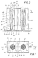
- FIGS 1 and 2 show a housing 10 through which two flow devices 12 and 14 are determined.
- a wall 16 with a diaphragm 18 is arranged between the two throughflow devices 12 and 14.
- the throughflow device 12 has an inner tube 20 and an outer tube 22 coaxially surrounding the inner tube 20.
- the outer tube 22 is arranged tightly between the bottom 24 and the cover 26 of the throughflow device 12.
- the outer tube 22 has recesses 28 in its central region, through which the inner space 30 between the inner tube 20 and the outer tube 22 with a collecting space 32 surrounding the outer tube 22 is fluid connected is.
- a filter element 38 is arranged on the outside of the outer tube 22 and covers the recesses 28 of the outer tube 22.
- This filter element 38 is designed as a filter cloth.
- Reference numeral 40 designates an outer coil which surrounds the filter device and thus the outer tube 22. The individual turns of the outer coil 40 are at a certain distance from one another, so that the electrical field present between the electrodes 42 and 44 of the flow-through device 12 is hardly affected by the outer coil 40.
- the electrodes 42 and 44 are in the collecting space surrounding the outer tube 22 32 arranged and electrically conductively connected to connections (not shown).
- An inner coil 46 surrounds the inner tube 20.
- the inner and outer tubes 20 and 22 are preferably made of a plastic material.
- the inner tube 20 is designed as a standing overflow. It is kept at a distance from the outer tube 22 by means of a spacer 48, which is designed, for example, as a perforated plate made of a plastic material.
- Reference numeral 50 denotes a cover flange which is designed with a degassing valve 52. Another degassing valve 52 is arranged in the cover 26 of the throughflow device 12.
- Reference numeral 54 denotes a supply line for the fluid, which opens through the floor 24 into the interior 30 of the throughflow device 12.
- the inner tube 20 is connected to a drain line 56, which forms the feed line for the adjacent flow device 14.
- the flow-through device 14 is constructed exactly the same as the flow-through device 12, so that it is not necessary to go into the individual parts of this flow-through device 14 again in detail.
- an anion concentrate is formed in the collecting space 32 of the throughflow device 12 at the top and a cation concentrate is deposited at the bottom, while an anion concentrate is deposited at the bottom in the outer space 32 of the throughflow device 14 and a cation concentrate is deposited at the top.
Landscapes
- Electrostatic Separation (AREA)
- Water Treatment By Electricity Or Magnetism (AREA)
- Cyclones (AREA)
- Current-Collector Devices For Electrically Propelled Vehicles (AREA)
- Physical Or Chemical Processes And Apparatus (AREA)
Priority Applications (1)
| Application Number | Priority Date | Filing Date | Title |
|---|---|---|---|
| AT88101070T ATE71855T1 (de) | 1987-02-05 | 1988-01-26 | Vorrichtung zur trennung geladener partikel von einem stroemungsmittel. |
Applications Claiming Priority (2)
| Application Number | Priority Date | Filing Date | Title |
|---|---|---|---|
| DE3703444 | 1987-02-05 | ||
| DE3703444A DE3703444C1 (enExample) | 1987-02-05 | 1987-02-05 |
Publications (3)
| Publication Number | Publication Date |
|---|---|
| EP0277581A2 EP0277581A2 (de) | 1988-08-10 |
| EP0277581A3 EP0277581A3 (en) | 1989-10-25 |
| EP0277581B1 true EP0277581B1 (de) | 1992-01-22 |
Family
ID=6320274
Family Applications (1)
| Application Number | Title | Priority Date | Filing Date |
|---|---|---|---|
| EP88101070A Expired - Lifetime EP0277581B1 (de) | 1987-02-05 | 1988-01-26 | Vorrichtung zur Trennung geladener Partikel von einem Strömungsmittel |
Country Status (3)
| Country | Link |
|---|---|
| EP (1) | EP0277581B1 (enExample) |
| AT (1) | ATE71855T1 (enExample) |
| DE (2) | DE3703444C1 (enExample) |
Families Citing this family (2)
| Publication number | Priority date | Publication date | Assignee | Title |
|---|---|---|---|---|
| JPH0677648B2 (ja) * | 1988-12-23 | 1994-10-05 | 株式会社日立製作所 | 導電性気液二相流の気液分離方法及びその装置 |
| US5224604A (en) * | 1990-04-11 | 1993-07-06 | Hydro Processing & Mining Ltd. | Apparatus and method for separation of wet and dry particles |
Family Cites Families (4)
| Publication number | Priority date | Publication date | Assignee | Title |
|---|---|---|---|---|
| SE338962B (enExample) * | 1970-06-04 | 1971-09-27 | B Lehnert | |
| JPS6044020B2 (ja) * | 1983-05-13 | 1985-10-01 | 株式会社ニチエレ | 空気流発生装置 |
| US4552664A (en) * | 1984-05-09 | 1985-11-12 | Benner Philip E | Method and apparatus for removing ions from a liquid |
| DE8701718U1 (de) * | 1987-02-05 | 1987-04-02 | Metzka, Hans-Joachim, 8500 Nürnberg | Vorrichtung zur Trennung geladener Partikel von einem Strömungsmittel |
-
1987
- 1987-02-05 DE DE3703444A patent/DE3703444C1/de not_active Expired
-
1988
- 1988-01-26 AT AT88101070T patent/ATE71855T1/de not_active IP Right Cessation
- 1988-01-26 EP EP88101070A patent/EP0277581B1/de not_active Expired - Lifetime
- 1988-01-26 DE DE8888101070T patent/DE3867857D1/de not_active Expired - Fee Related
Also Published As
| Publication number | Publication date |
|---|---|
| ATE71855T1 (de) | 1992-02-15 |
| EP0277581A3 (en) | 1989-10-25 |
| EP0277581A2 (de) | 1988-08-10 |
| DE3867857D1 (de) | 1992-03-05 |
| DE3703444C1 (enExample) | 1988-06-23 |
Similar Documents
| Publication | Publication Date | Title |
|---|---|---|
| DE102004034541B3 (de) | Hochgradienten-Magnetabscheider | |
| DE102010061952A1 (de) | Vorrichtung zum Abscheiden von ferromagnetischen Partikeln aus einer Suspension | |
| EP0111825B1 (de) | Vorrichtung der Hochgradienten-Magnettrenntechnik zum Abscheiden magnetisierbarer Teilchen | |
| EP2346612B1 (de) | Vorrichtung zum abscheiden ferromagnetischer partikel aus einer suspension | |
| EP1198296B1 (de) | Hochgradienten-magnetabscheider | |
| DE1442454B2 (de) | Vorrichtung zum reinigen von fluessigkeiten | |
| DE102008047841B4 (de) | Vorrichtung zum Abschneiden ferromagnetischer Partikel aus einer Suspension | |
| EP0277581B1 (de) | Vorrichtung zur Trennung geladener Partikel von einem Strömungsmittel | |
| EP0423827B1 (de) | Vorrichtung zur Aufbereitung von Flüssigkeiten, insbesondere von Wasser | |
| EP0815941B1 (de) | Hochgradienten-Magnetabscheider | |
| DE3827252C2 (enExample) | ||
| DE68922108T2 (de) | Vorrichtung zur kontinuierlichen Reinigung von Flüssigkeiten, insbesondere Wasser, durch Hochgradient-Magnetfiltration. | |
| DE2501858C2 (de) | Vorrichtung zum Abscheiden magnetisierbarer Teilchen, die in einer Flüssigkeit suspendiert sind | |
| DE2111986C3 (de) | Magnetischer Naßabscheider | |
| DE8701718U1 (de) | Vorrichtung zur Trennung geladener Partikel von einem Strömungsmittel | |
| DE820085C (de) | Filter | |
| DE2461760C3 (de) | Freifall-Magnetscheider | |
| DE102017105291B4 (de) | Magnetabscheider zur Abscheidung ferromagnetischer Partikel aus einem Absaugluftstrom | |
| DE977427C (de) | Kombiniert magnet-mechanisch wirkendes Fluessigkeitssiebfilter | |
| DE19857730A1 (de) | Wasser-Konditionierungs-Gerät zur Modifizierung der Kalk-Ausfällung | |
| EP0501033A1 (de) | Filter zur Abscheidung ferromagnetischer und/oder paramagnetischer Verunreinigungen aus dünnflüssigen Medien | |
| DE2914497C2 (de) | Magnetfilter | |
| DE420278C (de) | Magnetscheider | |
| DE1106712B (de) | Magnetisch oder elektrostatisch-magnetisch wirkende Vorrichtung zur Abscheidung magnetisierbarer Teile | |
| DE2428273C3 (de) | Magnetschneider zum Sortieren von Stoff gemischen |
Legal Events
| Date | Code | Title | Description |
|---|---|---|---|
| PUAI | Public reference made under article 153(3) epc to a published international application that has entered the european phase |
Free format text: ORIGINAL CODE: 0009012 |
|
| AK | Designated contracting states |
Kind code of ref document: A2 Designated state(s): AT BE CH DE ES FR GB GR IT LI LU NL SE |
|
| PUAL | Search report despatched |
Free format text: ORIGINAL CODE: 0009013 |
|
| AK | Designated contracting states |
Kind code of ref document: A3 Designated state(s): AT BE CH DE ES FR GB GR IT LI LU NL SE |
|
| 17P | Request for examination filed |
Effective date: 19900414 |
|
| 17Q | First examination report despatched |
Effective date: 19910624 |
|
| GRAA | (expected) grant |
Free format text: ORIGINAL CODE: 0009210 |
|
| AK | Designated contracting states |
Kind code of ref document: B1 Designated state(s): AT BE CH DE ES FR GB GR IT LI LU NL SE |
|
| PG25 | Lapsed in a contracting state [announced via postgrant information from national office to epo] |
Ref country code: IT Free format text: LAPSE BECAUSE OF FAILURE TO SUBMIT A TRANSLATION OF THE DESCRIPTION OR TO PAY THE FEE WITHIN THE PRE;WARNING: LAPSES OF ITALIAN PATENTS WITH EFFECTIVE DATE BEFORE 2007 MAY HAVE OCCURRED AT ANY TIME BEFORE 2007. THE CORRECT EFFECTIVE DATE MAY BE DIFFERENT FROM THE ONE RECORDED.SCRIBED TIME-LIMIT Effective date: 19920122 Ref country code: GB Effective date: 19920122 Ref country code: ES Free format text: THE PATENT HAS BEEN ANNULLED BY A DECISION OF A NATIONAL AUTHORITY Effective date: 19920122 Ref country code: NL Effective date: 19920122 Ref country code: GR Free format text: LAPSE BECAUSE OF FAILURE TO SUBMIT A TRANSLATION OF THE DESCRIPTION OR TO PAY THE FEE WITHIN THE PRESCRIBED TIME-LIMIT Effective date: 19920122 Ref country code: SE Effective date: 19920122 Ref country code: BE Effective date: 19920122 |
|
| REF | Corresponds to: |
Ref document number: 71855 Country of ref document: AT Date of ref document: 19920215 Kind code of ref document: T |
|
| PG25 | Lapsed in a contracting state [announced via postgrant information from national office to epo] |
Ref country code: LU Free format text: LAPSE BECAUSE OF NON-PAYMENT OF DUE FEES Effective date: 19920131 |
|
| REF | Corresponds to: |
Ref document number: 3867857 Country of ref document: DE Date of ref document: 19920305 |
|
| EN | Fr: translation not filed | ||
| PG25 | Lapsed in a contracting state [announced via postgrant information from national office to epo] |
Ref country code: FR Effective date: 19920612 |
|
| NLV1 | Nl: lapsed or annulled due to failure to fulfill the requirements of art. 29p and 29m of the patents act | ||
| GBV | Gb: ep patent (uk) treated as always having been void in accordance with gb section 77(7)/1977 [no translation filed] | ||
| PLBE | No opposition filed within time limit |
Free format text: ORIGINAL CODE: 0009261 |
|
| STAA | Information on the status of an ep patent application or granted ep patent |
Free format text: STATUS: NO OPPOSITION FILED WITHIN TIME LIMIT |
|
| 26N | No opposition filed | ||
| REG | Reference to a national code |
Ref country code: FR Ref legal event code: ST |
|
| PGFP | Annual fee paid to national office [announced via postgrant information from national office to epo] |
Ref country code: CH Payment date: 19950105 Year of fee payment: 8 |
|
| PGFP | Annual fee paid to national office [announced via postgrant information from national office to epo] |
Ref country code: AT Payment date: 19950131 Year of fee payment: 8 |
|
| PG25 | Lapsed in a contracting state [announced via postgrant information from national office to epo] |
Ref country code: AT Effective date: 19960126 |
|
| PG25 | Lapsed in a contracting state [announced via postgrant information from national office to epo] |
Ref country code: CH Effective date: 19960131 Ref country code: LI Effective date: 19960131 |
|
| REG | Reference to a national code |
Ref country code: CH Ref legal event code: PL |
|
| PGFP | Annual fee paid to national office [announced via postgrant information from national office to epo] |
Ref country code: DE Payment date: 19961111 Year of fee payment: 10 |
|
| PG25 | Lapsed in a contracting state [announced via postgrant information from national office to epo] |
Ref country code: DE Free format text: LAPSE BECAUSE OF NON-PAYMENT OF DUE FEES Effective date: 19981001 |