EP0276368B1 - Einrichtung zur Fernmessung der Temperatur - Google Patents
Einrichtung zur Fernmessung der Temperatur Download PDFInfo
- Publication number
- EP0276368B1 EP0276368B1 EP87114239A EP87114239A EP0276368B1 EP 0276368 B1 EP0276368 B1 EP 0276368B1 EP 87114239 A EP87114239 A EP 87114239A EP 87114239 A EP87114239 A EP 87114239A EP 0276368 B1 EP0276368 B1 EP 0276368B1
- Authority
- EP
- European Patent Office
- Prior art keywords
- pulse
- pulses
- sensing units
- modulation
- measurement
- Prior art date
- Legal status (The legal status is an assumption and is not a legal conclusion. Google has not performed a legal analysis and makes no representation as to the accuracy of the status listed.)
- Expired - Lifetime
Links
- 238000005259 measurement Methods 0.000 claims abstract description 33
- 230000015654 memory Effects 0.000 claims description 17
- 239000010453 quartz Substances 0.000 claims description 3
- VYPSYNLAJGMNEJ-UHFFFAOYSA-N silicon dioxide Inorganic materials O=[Si]=O VYPSYNLAJGMNEJ-UHFFFAOYSA-N 0.000 claims description 3
- 230000010355 oscillation Effects 0.000 claims description 2
- 239000012429 reaction media Substances 0.000 claims 1
- 238000011156 evaluation Methods 0.000 description 41
- 239000004020 conductor Substances 0.000 description 18
- 230000005540 biological transmission Effects 0.000 description 13
- 238000011161 development Methods 0.000 description 9
- 230000018109 developmental process Effects 0.000 description 9
- 238000010586 diagram Methods 0.000 description 6
- 238000009434 installation Methods 0.000 description 6
- 238000010438 heat treatment Methods 0.000 description 5
- 239000000126 substance Substances 0.000 description 5
- 238000009529 body temperature measurement Methods 0.000 description 4
- 238000001816 cooling Methods 0.000 description 4
- 230000003111 delayed effect Effects 0.000 description 3
- 230000004044 response Effects 0.000 description 3
- 230000000630 rising effect Effects 0.000 description 3
- 230000003213 activating effect Effects 0.000 description 2
- 239000013078 crystal Substances 0.000 description 2
- 230000001419 dependent effect Effects 0.000 description 2
- 230000007613 environmental effect Effects 0.000 description 2
- 239000013642 negative control Substances 0.000 description 2
- 238000001208 nuclear magnetic resonance pulse sequence Methods 0.000 description 2
- 230000002123 temporal effect Effects 0.000 description 2
- 230000004913 activation Effects 0.000 description 1
- 230000008901 benefit Effects 0.000 description 1
- 238000009530 blood pressure measurement Methods 0.000 description 1
- 239000007795 chemical reaction product Substances 0.000 description 1
- 238000001514 detection method Methods 0.000 description 1
- 230000004069 differentiation Effects 0.000 description 1
- 230000000694 effects Effects 0.000 description 1
- 230000006870 function Effects 0.000 description 1
- 239000007788 liquid Substances 0.000 description 1
- 238000004519 manufacturing process Methods 0.000 description 1
- 238000000034 method Methods 0.000 description 1
- 238000012986 modification Methods 0.000 description 1
- 230000004048 modification Effects 0.000 description 1
- 238000012545 processing Methods 0.000 description 1
- 239000000376 reactant Substances 0.000 description 1
- 239000011541 reaction mixture Substances 0.000 description 1
- 239000004065 semiconductor Substances 0.000 description 1
- 239000007787 solid Substances 0.000 description 1
- 238000012546 transfer Methods 0.000 description 1
- 230000001960 triggered effect Effects 0.000 description 1
Images


Classifications
-
- G—PHYSICS
- G08—SIGNALLING
- G08C—TRANSMISSION SYSTEMS FOR MEASURED VALUES, CONTROL OR SIMILAR SIGNALS
- G08C15/00—Arrangements characterised by the use of multiplexing for the transmission of a plurality of signals over a common path
-
- G—PHYSICS
- G01—MEASURING; TESTING
- G01K—MEASURING TEMPERATURE; MEASURING QUANTITY OF HEAT; THERMALLY-SENSITIVE ELEMENTS NOT OTHERWISE PROVIDED FOR
- G01K1/00—Details of thermometers not specially adapted for particular types of thermometer
- G01K1/02—Means for indicating or recording specially adapted for thermometers
- G01K1/026—Means for indicating or recording specially adapted for thermometers arrangements for monitoring a plurality of temperatures, e.g. by multiplexing
Definitions
- the invention relates to a device for remote measurement of the temperature or another physical variable at a plurality of measuring points according to the preamble of claim 1.
- Such a device is described in DE-PS 3 128 706.
- the various sensing units that are assigned to the individual measuring points are connected to a common data rail and each send successive pulses at a greater distance, the distance between which corresponds to the instantaneous value of the variable to be recorded at the measuring point.
- the pulses provided by the various sensing units are interleaved, which is achieved by applying a starting pulse provided by the central evaluation unit to the individual sensing units via a delay circuit specifically set for them.
- the sensor unit can transfer additional data to the evaluation unit, e.g. Data for identifying the working characteristic of the sensor contained in a sensor unit under consideration, data that characterize a parameter of the measuring point under consideration, etc.
- additional data can in principle also be stored in the central evaluation unit, in this case it is the structure of the entire measuring system and later also necessary when exchanging sensing units. to program the evaluation unit accordingly.
- this additional programming of the evaluation unit which also represents a further possibility of error, could be omitted.
- DE-A 2 707 420 describes a method for the transmission of several parameters on message channels operated in parallel. Two measured variables are transmitted per channel in such a way that the modulation in the respective channel assumes two periodically successive states, the lengths of which are analogous to the amounts of the measured variables.
- An oscillator is mentioned as an example, the output signal of which is a pulse train of rectangular-shaped signals which has an obedend t f dependent on the moisture resistance and an undersize tp controlled by the barometer-controlled resistance.
- DE-A 2 701 039 a device which supplies a coded signal, the code sequence of which indicates a first polled environmental condition and the frequency of which indicates a second polled environmental condition.
- a depth pressure and temperature measurement in an oil borehole is described in the exemplary embodiment.
- the pressure is represented by a sequence of pulses, which, however, can only take two different pulse heights as digital digits; the temperature corresponds to the duration of the pulses.
- a device for remote measurement of the temperature or another physical quantity at a plurality of measuring points according to the preamble of claim 1 is to be developed in such a way that, while maintaining a simple two-wire data rail, additional information from the actual measurement signal Sensing units can be transferred to the evaluation unit.
- the telemetry device there are a total of two or three nested data transmission channels: First, the main data transmission channel for the measurement data, which consist of a distance-modulated pulse sequence; then a second data transmission channel with a lower resolution in practice, which is obtained by additionally modulating the width of the pulses modulated to transmit the main information; finally a third data transmission channel, which is obtained by additionally modulating the amplitude of the distance-modulated pulses for the transmission of the measurement data.
- Secondary information can be sent via the second data channel, e.g. Information about the characteristic curve of the sensor used in the sensor unit under consideration (for an essentially linear characteristic curve, e.g. the slope and the zero signal or two points of the characteristic curve, which means that fluctuations in the characteristic curve due to production can be automatically taken into account) or information about the installation conditions of the Sensor at the measuring point or information about the current ambient conditions under which the sensor works (for temperature measurement in a chemical reactor, for example, information about whether the reactor is currently being heated or cooled).
- Information about the characteristic curve of the sensor used in the sensor unit under consideration for an essentially linear characteristic curve, e.g. the slope and the zero signal or two points of the characteristic curve, which means that fluctuations in the characteristic curve due to production can be automatically taken into account
- information about the installation conditions of the Sensor at the measuring point or information about the current ambient conditions under which the sensor works for temperature measurement in a chemical reactor, for example, information about whether the reactor is currently being heated or cooled).
- a telemetry device with two data transmission channels can be implemented with little additional structural outlay.
- the development of the invention according to claim 2 represents a particularly simple way of generating additional information for a sensor unit under consideration.
- a plurality of different memory circuits can be provided as a plug-in element, one of which is suitable for the installation unit under consideration when the sensor unit is attached by the installation personnel is inserted into a socket. If the various storage circuits are appropriately labeled, the installation personnel need not have any knowledge of the programming of the evaluation unit.
- a second measured variable is transmitted to the evaluation unit in addition to the main measured variable via the additionally obtained data transmission channel.
- the temperature at the measuring point as the main measured variable: the density or the pressure of gaseous reactants in a chemical reactor in which the temperature is measured, the moisture content of the reaction mixture in this reactor, the amount of liquid or solid reaction products, that have formed in the reactor and have to be withdrawn periodically, the temperature prevailing outside the reactor in the factory hall, details of the working state of a heating device and / or cooling device of the reactor, etc.
- addressable changeover switches can be controlled with the additionally wide or amplitude-modulated impulses, Via which sub-data rails can be coupled to or separated from a main data rail.
- telemetry devices with a very large number of sensing units can also be implemented using a relatively small total number of different phase modulation or delay circuits for the individual sensing units.
- control pulses are distinguishable from themselves from measurement pulses.
- the evaluation unit can distinguish the control impulses from measurement impulses by knowing the time of their generation.
- the remote measuring device can in principle be implemented both with voltage pulses and with current pulses. With the development of the invention according to claim 9, however, it is achieved that the energy supply for the various sensing units can be accomplished particularly well from the data rail itself, even if the measuring pulses transmitted via the data rail follow one another at a short distance.
- FIG. 1 shows schematically a temperature remote measurement system, which is explained in connection with only twelve measuring points for the sake of clarity. In practice, such a measuring system can easily include a thousand or more measuring points.
- Two conductors 12, 14 are connected to a central evaluation unit 10 for all measuring points.
- the conductors 12, 14 form a main data rail.
- three addressable rail changeover switches 18-1, 18-2 and 18-3 are connected to these. These each have a controllable bridge 20, which can establish or interrupt a connection to the conductor 12.
- a control unit 22 which taps its control signals from the conductors 12, 14, is used to control the bridges 20.
- a network unit 24, which supplies the various components of a rail switch 18 with energy, is also connected to the conductors 12, 14.
- Conductors 26, 28 are each connected to a rail switch 18. Together, these form a sub-data rail, which, depending on the position of the bridge 20, can be connected to or separated from the main data rail formed by the conductors 12, 14.
- Sensing units 32-38 are connected to the sub-data rail formed by the conductors 26, 28, each of which can modulate the basic current led by the conductors 26, 28 (measuring pulses) and to certain voltage pulses generated by the evaluation unit 10 and supplied via these conductors respond (control impulses). The structure of the sensing units 32-38 is explained in more detail below.
- each of the sensing units 32-38 contains a temperature sensor 38c, a pulse generator 38b frequency-controlled by its output signal and a switching stage 38a actuated by the latter, so that the sensing unit as a whole provides successive pulses, the distance between which is a measure of the temperature at the sensing unit is.
- Typical temperature sensors suitable for this are quartz crystals cut to the temperature response with downstream frequency divider circuits.
- the sensing units each monitor the temperature in an associated chemical reactor (not shown) in which gaseous substances are reacted.
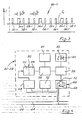
- FIG. 2a shows schematically the time profile of the voltage on the conductors 12, 14.
- the evaluation unit 10 maintains a basic voltage Vo on these conductors. Negative control pulses 42 are superimposed on this by the evaluation unit in order to control the operation of the rail changeover switch 18 and the sensing units 32-38.
- the negative control pulses 42 serve on the one hand as addressing pulses, by means of which one of the rail changeover switches 18 is brought into the working state with the bridge 20 closed, while the other rail changeover switches are in the open state remain. Addressing one the rail switch 18 for About the width of the control pulse 42th embodiment considered here, assume that the rail switch 18-1 closes at a pulse width a, the rail switch 18-2 at a pulse width 2a and the rail switch 18-3 at a pulse width of 3a.
- the evaluation unit 10 Via the rising rear edge 44 of the control pulses 42, the evaluation unit 10 also starts the work of the various sensing units 32-38 in that sub-data rail which was addressed by the assigned control pulse and was thus connected to the main data rail. Now the various sensing units 32-38 connected to the sub-data rail begin to modulate the basic current 1 0 , which the evaluation unit 10 sets on the conductors 12, 14 (cf. FIG. 2 b) by indicating successive current pulses (schematic at 46) ), where the distance between successive current pulses generated by a sensing unit is a measure of the temperature prevailing in this sensing unit.
- the temperature response based on frequency-based temperature sensors is relatively small, so that if one does not want to evaluate the pulse position with very high resolution, one must evaluate successive ones of the pulses at a greater distance.
- this is done by adding a frequency divider to the actual temperature sensor and only evaluating successive pulses generated by the sensor with respect to the phase position at intervals of, for example, half a second.
- the time within which a certain one of the sensing units 32-38 on the current-based data rail does not provide any pulses is used to transmit the pulses of other sensing units to the data rail, so that the measuring pulses of the different sensing units are nested, as shown in FIG. 3 evident.
- a pulse width b1 is intended to indicate that a heating device (not shown) of the reactor which is associated with the sensor unit under consideration is switched on; on the other hand, a pulse width b 2 is intended to indicate that the heating device in question is switched off.
- Other different pulse widths can be used to code the working state of a cooling device of the reactor.
- the temperature or another physical variable in the reactor can then be controlled more purposefully.
- the conductors 12, 14 form a main data rail, to which one of three sub-data rails in the exemplary embodiment can optionally be connected.
- the evaluation unit 10 receives main information from the sensing units 32-38 with high resolution (with respect to that in the Sensing unit prevailing temperature, represented by pulse distance modulation) as well as additional information acquired with low resolution (e.g. sensor characteristic or working state of a heating or cooling device at the measuring point, represented by additional modulation of the pulse width).
- the corresponding pulse packets of a sub-data rail are denoted overall by 46 in FIG. 2b.
- FIG. 4 shows details of the structure of one of the sensing units 32-38. These units each have a pulse detector 48 which is connected to the data rail of the sub-data rail and which transmits negative voltage pulses on the conductors 26, 28 on the output side as positive voltage pulses. These voltage pulses serve to start a temperature sensor 50, which consists of a quartz crystal 52 cut to the temperature response of its oscillation frequency and a frequency divider 54 connected downstream. The output frequency of the frequency divider 54 is typically 4 Hz.
- the output signal of the temperature sensor 50 which consists of a sequence of pulses of a predetermined width and temperature-dependent distance, is applied to a pulse width modulator 58 via an adjustable delay circuit 56. The extent of the signal delay caused by the delay circuit 56 is predetermined by a delay setting circuit 60.
- the width modulator 58 modifies the width of the pulses emitted by the temperature sensor 50 while maintaining its front pulse edge as a function of the signal present at its control terminal.
- This signal is provided by a transmitter 62, the output signal of which corresponds to an additional information to be transmitted from the sensor unit under consideration to the evaluation unit.
- the encoder 62 can e.g. be a read-only memory which emits a preset signal assigned to the characteristic curve of the temperature sensor 50. This signal can in turn comprise several pieces of information, e.g. Zero point shift, slope and curvature of the characteristic or some characteristic characteristic points.
- the transmitter 62 can also generate a signal assigned to the set output of the reactor heating or cooling or a signal assigned to another secondary measured variable.
- the encoder 62 can also comprise an analog or digital sensor or have a switch bank 64 or a simple switch instead of a semiconductor read-only memory (ROM), the width modulator 58 being adapted to the output signal of the encoder 62, e.g. when using a sensor emitting an analog voltage signal has a voltage-controlled monostable multivibrator which is triggered by the pulses emitted by the delay circuit 56.
- ROM semiconductor read-only memory
- a current modulation circuit 66 which is also connected to the sub-data rail, is controlled by the output signals of the temperature sensor 50 modified by the width modulator 58 with regard to the pulse width, which e.g. can consist of a resistor 68 and a series-connected bridge 70.
- Bridge 70 is normally open and is closed by an activation pulse applied to modulation circuit 66, which leads to a positive current pulse on the sub-data rail and thus also in the main data rail.
- a network circuit 72 is used to derive the energy supply for the various components of the sensing unit from the base current lo maintained by the evaluation unit 10.
- Figure 5 shows details of a rail switch.
- Each rail changeover switch 18 has a pulse detector 76, which is constructed similarly to the pulse detectors 48 of the sensing units, also responds to negative voltage pulses and converts them into positive voltage pulses of the same length.
- the latter has an edge detector 78 triggering on rising edges and an edge detector 80 triggering on falling edges applied to it.
- Their output signals are given to the set or reset terminal of a bistable multivibrator 82. Its "1" output is used to activate a free-running frequency generator 84.
- the pulses obtained at the output of the latter reach the counting terminal C of a counter 86, the reset terminal R of which is supplied with the output signal of the edge detector 78.
- the output signal of the edge detector 80 triggemden on falling edges not only resets the bistable flip-flop 82, which ends the delivery of pulses by the frequency generator 84, it also triggers a comparator 88, the input side with the output signal of the counter 86 and the Output signal of an address setting circuit 90 is applied.
- the rail switch 18 also contains the network circuit 24 already mentioned above, which derives the energy required to operate the various components from the base current lo.
- the evaluation unit 10 initially contains a voltage source 94 for setting the basic current lo on the main data rail 12, 14 and the sub-data rails just connected.
- a control pulse generator 96 is connected via the terminals of the voltage source 94. This can have a resistor 100 and a normally open switching bridge 98, the latter being applied to the control terminal of the control pulse generator 96 the signal is closed in order to apply a negative voltage pulse to the basic voltage Vo.
- the internal resistance of the voltage source 94 is small compared to the short-circuit resistor 68 of the sensing units and large compared to the short-circuit resistor 100, so that the bridge 70 is closed to a current pulse, the bridge 98 is closed to a voltage pulse on the main data rail 12 , 14 leads.
- the control signals for the control pulse generator 96 are provided by a freely programmable computer 104, which cooperates with a mass storage device 106 and is loaded with a program which determines the timing of the switchover to the various sub-data rails, the retrieval of the measurement pulse packages 46 and theirs Controls evaluation and storage.
- the computer 104 places to the control pulse generator 96 pulses of length a, 2a and 3a in order to connect the various sub-data rails to the main data rail in any order.
- the free programmability of the addressing of the rail changeover switch 18 enables some of the sub-data rails that are of less interest to be queried less often overall than others of the sub-data rails.
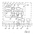
- the falling rear edge of a pulse given by the computer 104 to the control pulse generator 96 also starts an evaluation circuit 108, which is inserted into the current loop from the voltage source 94, main data rail and connected sub-data rail. Details of the evaluation circuit 108 will now be explained in more detail with reference to FIG. 7.
- the evaluation circuit 108 contains a pulse detector 110 inserted into the data rail, which only responds to positive current pulses and, if there is one, provides a positive voltage pulse at its output. This arrives at the inputs of an edge detector 112 triggging on positive edges and an edge detector 114 trigging on negative edges.
- the output signal of the edge detector 112 drives the write control terminal EW of a read / write memory 116.
- the data input terminal DI of the read / write memory 116 is supplied with the data output DO of a counter 118, the counter terminal C of which is continuously supplied with counting pulses by a free-running frequency generator 120.
- the reset terminal of the counter 118 is acted upon by the evaluation start signal provided by the computer 104.
- the data output of the counter 118 is also connected to the data input D1 of a second read / write memory 122.
- the write control terminal EW is acted upon by the signal at the output of the edge detector 114 triggemden on negative edges.
- the data output terminals DO of the two read / write memories 116 and 122 are connected to the inputs of a subtraction circuit 124.
- the output signal of the edge detector 114 which is delayed by a delay element 126, is used to control the read-out control terminals ER of the two read / write memories 116 and 122.
- the output signal of the delay element 126 is delayed again by a further delay element 128 and is used to activate the subtractor circuit 124.
- the output signal of the subtracting circuit 124 thus corresponds to the width of a positive current pulse on the data rail detected by the pulse detector 110, while the content of the read / write memory 116 corresponds to the position of the rising edge of this pulse.
- the output signal of the read / write memory 116 is converted into the higher-order bits of a e.g. 16 bit long data word set, while the output signal of the subtracting circuit 124 is applied to the least significant bits of this word.
- the combination circuit 130 is activated by the output signal of the delay element 128, which is delayed by a further delay element 132.
- the output signal of the delay element 132 is at the same time given to the computer 104 via a line 134 in order to indicate that a further measurement data word is available for acceptance and further processing. This word is transmitted from the combination circuit 130 to the computer 104 via a data line 136.
- the read / write memory 116 provides its content at its data output terminal DO both when activating the subtracting circuit 124 and when activating the combination circuit 130, it is connected via an OR gate 138 to the output signal of both the delay element 126 and the delay element 128 acted upon.
- the evaluation circuit 108 in turn has a network circuit 140 for deriving the supply voltages from the base current lo.
- both the position of a measurement data pulse and its width are determined by reading out the status of a single counter 118 at different times.
- the counter 118 could only be used to determine the position of a measurement data pulse and the width thereof could be determined using a separate pulse width discriminator, as shown at 92 in FIG.
- the resolution when determining the pulse width can then also be selected differently from the temporal resolution when determining the pulse position.
- the information to be transmitted additionally from a sensing unit to the central evaluation unit was in the width of the distance-modulated pulses for the main information (temperature).
- this additional information can also be obtained by modulating the amplitude of the distance-modulated pulses for transmission main information.
- the sensing units 32-1 - 38-1 transmit additional information, which can be designated "1", "2" and "3", in the form of pulse amplitudes of sizes A / 3, 2A / 3 and A.
- This different additional information can again stand for different values for the characteristic curve of the temperature sensor used or other secondary measurement information.
- FIG. 9 shows an amplitude discriminator 142, which can be provided in the evaluation circuit 108 for the detection of three different pulse heights.
- Three resistors 144, 146, 148 are connected in the conductor 14, the values of which behave as one to two to three.
- a series circuit comprising a resistor 150 and a Zener diode 152 is connected in each case via the resistors 144-148.
- the voltage drops at the Zener diodes 152 are applied to the inputs of differential amplifiers 154, 156, 158, which thus provide an output signal when the current pulse reaches level A / 3, 2A / 3 or A indicated in FIG.
- the amplitude discriminator 142 according to FIG. 9 can be followed by a coding network which converts the total signal obtained by the output signals at the differential amplifiers 154 to 158 into the numbers "1", "2" and "3".
- the amplitude modulation of the measurement data pulses can also be combined with the pulse width modulation according to FIG. 3, whereby two additional information channels are then opened on the data rail, via which two additional information items relevant to the measurement are then obtained with low resolution Sensing units 32-38 of the respectively addressed sub-data rail can be transferred to the evaluation unit 10.
- the amplitude discriminator 142 is inserted in FIG. 7, as indicated by dashed lines.
- Combination circuit 130 then forms a further part of the measurement data word output to computer 104 via data line 136 from the output signal of amplitude discriminator 142.
Landscapes
- Physics & Mathematics (AREA)
- General Physics & Mathematics (AREA)
- Arrangements For Transmission Of Measured Signals (AREA)
Applications Claiming Priority (2)
| Application Number | Priority Date | Filing Date | Title |
|---|---|---|---|
| DE3701082 | 1987-01-16 | ||
| DE19873701082 DE3701082A1 (de) | 1987-01-16 | 1987-01-16 | Einrichtung zur fernmessung der temperatur |
Publications (2)
| Publication Number | Publication Date |
|---|---|
| EP0276368A1 EP0276368A1 (de) | 1988-08-03 |
| EP0276368B1 true EP0276368B1 (de) | 1990-09-19 |
Family
ID=6318914
Family Applications (1)
| Application Number | Title | Priority Date | Filing Date |
|---|---|---|---|
| EP87114239A Expired - Lifetime EP0276368B1 (de) | 1987-01-16 | 1987-09-30 | Einrichtung zur Fernmessung der Temperatur |
Country Status (3)
| Country | Link |
|---|---|
| US (1) | US4916643A (enExample) |
| EP (1) | EP0276368B1 (enExample) |
| DE (2) | DE3701082A1 (enExample) |
Families Citing this family (37)
| Publication number | Priority date | Publication date | Assignee | Title |
|---|---|---|---|---|
| DE3912658C2 (de) * | 1989-04-18 | 2000-03-02 | Mannesmann Vdo Ag | Verfahren und Anordnung zur Temperaturmessung |
| DE3933311A1 (de) * | 1989-10-05 | 1991-04-18 | Endress Hauser Gmbh Co | Temperaturmessschaltung |
| US5035511A (en) * | 1990-04-10 | 1991-07-30 | The Babcock & Wilcox Company | Distributed fiber optic temperature sensor based on time domain transmission |
| SE9100534D0 (sv) * | 1991-02-25 | 1991-02-25 | Asea Brown Boveri | Temperaturmaetsystem |
| DE4200578A1 (de) * | 1992-01-11 | 1993-07-15 | Heraeus Sensor Gmbh | Temperatur-sensor mit piezoelektrischem schwingkristall |
| US5291422A (en) * | 1992-01-28 | 1994-03-01 | Sgi International | Broadband instrument for nondestructive measurement of material properties |
| DE4210189C2 (de) * | 1992-03-30 | 1994-12-22 | Heraeus Sensor Gmbh | Vorrichtung und Verfahren zur Fernmessung der Temperatur |
| US5299869A (en) * | 1992-08-19 | 1994-04-05 | Hughes Aircraft Company | Laser diode temperature sensing system |
| ES2078858B1 (es) * | 1993-08-25 | 1997-12-01 | Cerda Juan Nicolas Oller | Dispositivo electronico autonomo de registro y transmision de datos aplicable en aparatos contadores y registradores en general. |
| DE4332022C2 (de) * | 1993-09-21 | 1997-07-03 | Tr Elektronic Gmbh | Verfahren und Vorrichtung zum berührungslosen Erfassen der Winkellage eines Objekts, insbesondere beim Vermessen von länglichen Gegenständen |
| DE4408898C2 (de) * | 1994-03-16 | 1999-08-19 | Koster | Fernkalibrierbare Temperaturmeßvorrichtung |
| DE19618867A1 (de) | 1995-08-26 | 1997-02-27 | Bosch Gmbh Robert | System zur Veränderung eines Drehzahlsignals |
| EP0788645B1 (de) * | 1995-08-26 | 2003-03-12 | Robert Bosch Gmbh | System zur veränderung eines drehzahlsignals |
| DE19717933A1 (de) * | 1997-04-29 | 1998-11-05 | Thomson Brandt Gmbh | Schaltungsanordnung mit einem Geber und einer Auswerteschaltung |
| DE19850258A1 (de) * | 1998-10-31 | 2000-05-11 | Daimler Chrysler Ag | Verfahren zur Auswertung eines Signals sowie Erkennung eines Gerätetyps |
| DE19907950C2 (de) * | 1999-02-24 | 2002-01-10 | Siemens Ag | Meßvorrichtung |
| DE19941465A1 (de) * | 1999-09-01 | 2001-03-15 | Hella Kg Hueck & Co | Positionssensor für ein Kraftfahrzeug |
| DE10021573A1 (de) * | 2000-05-03 | 2001-11-15 | Knorr Bremse Systeme | Verfahren und Einrichtung zur Bereitstellung von Signalen in Fahrzeugen |
| US6864802B2 (en) | 2000-09-01 | 2005-03-08 | Ut-Battelle, Llc | Wireless spread-spectrum telesensor chip with synchronous digital architecture |
| AU2003241519A1 (en) * | 2002-05-21 | 2003-12-12 | Acrolon Technologies, Inc. | System and method for temperature sensing and monitoring |
| DE10346965A1 (de) * | 2003-10-09 | 2005-06-02 | Siemens Ag | Spannungsregelung für räumlich entfernte Verbraucher |
| DE102004048928B4 (de) * | 2004-10-06 | 2008-03-13 | Sew-Eurodrive Gmbh & Co. Kg | Temperatursensor und Elektromotor |
| US7737838B2 (en) * | 2005-10-03 | 2010-06-15 | Gm Global Technology Operations, Inc. | Method and apparatus for transmission of wireless signals in a mobile platform |
| KR100656431B1 (ko) * | 2005-11-09 | 2006-12-11 | 주식회사 하이닉스반도체 | 트랜지스터를 이용한 온도 감지 장치 |
| US7412347B2 (en) * | 2006-01-23 | 2008-08-12 | Sherwood Engineering Design Services, Inc. | Method and apparatus for measuring physical parameters |
| US8018323B2 (en) * | 2006-01-30 | 2011-09-13 | Baohua Qi | RFID sensor device based on pulse-processing |
| US8013714B2 (en) * | 2006-03-27 | 2011-09-06 | Baohua Qi | RFID sensor using pulse processing |
| US7496469B2 (en) * | 2006-05-19 | 2009-02-24 | Watlow Electric Manufacturing Company | Temperature sensor adaptors and methods |
| US7496481B2 (en) * | 2006-05-19 | 2009-02-24 | Watlow Electric Manufacturing Company | Sensor adaptors and methods |
| US7470060B1 (en) * | 2006-06-23 | 2008-12-30 | Innovative Measurement Methods, Inc. | Detection apparatus for measuring fluid in a vessel |
| US8026795B2 (en) * | 2007-02-22 | 2011-09-27 | Baohua Qi | RFID sensor array and sensor group based on pulse-processing |
| US20090299953A1 (en) * | 2008-06-02 | 2009-12-03 | Ted Wayne Sunderland | Merchandiser with automated report generation system |
| JP5278475B2 (ja) * | 2011-03-28 | 2013-09-04 | 株式会社デンソー | 情報伝達装置 |
| DE102012219501A1 (de) * | 2012-10-25 | 2014-04-30 | BSH Bosch und Siemens Hausgeräte GmbH | Sensoranordnung für eine Haushaltsgerät sowie ein Haushaltsgerät mit einer derartigen Sensoranordnung |
| US9076272B2 (en) * | 2013-05-28 | 2015-07-07 | Infineon Technologies Ag | Wheel speed sensor and interface systems and methods |
| US9746307B2 (en) | 2014-10-07 | 2017-08-29 | Faro Technologies, Inc. | Coordinate measurement machine with configurable articulated arm bus |
| US20250271516A1 (en) * | 2024-02-23 | 2025-08-28 | Infineon Technologies Ag | Diagnostic interface for sensor package |
Family Cites Families (15)
| Publication number | Priority date | Publication date | Assignee | Title |
|---|---|---|---|---|
| GB1101122A (en) * | 1964-04-02 | 1968-01-31 | Evershed Vignoles Ltd | Improvements relating to data transmission systems |
| US3821559A (en) * | 1973-01-02 | 1974-06-28 | Mitsubishi Electric Corp | Control system for electric installations |
| DE2701039A1 (de) * | 1977-01-12 | 1978-07-20 | Lynes Inc | Messgeraet fuer umweltbedingungen |
| DE2707420A1 (de) * | 1977-02-21 | 1978-08-24 | Sprenger Albin Kg | Radiosondensystem |
| DE3025837C2 (de) * | 1980-07-08 | 1987-05-07 | MTC, Meßtechnik und Optoelektronik AG, Neuenburg/Neuchâtel | Meßanordnung mit einer Vielzahl von miteinander durch ein Kabel verbundenen Meßstellen |
| DE3128706C2 (de) * | 1981-07-21 | 1985-11-14 | Horst Prof. Dr. 4790 Paderborn Ziegler | Fühleinheit zur Fernmesssung des Wärmeverbrauches an einer Mehrzahl von Verbrauchsstellen |
| US4531193A (en) * | 1981-07-30 | 1985-07-23 | Fuji Electric Company, Ltd. | Measurement apparatus |
| US4481596A (en) * | 1981-11-02 | 1984-11-06 | Kaye Instruments Inc. | Method of and apparatus for automatically compensating for variations in output response characteristics of sensors and the like |
| US4471354A (en) * | 1981-11-23 | 1984-09-11 | Marathon Medical Equipment Corporation | Apparatus and method for remotely measuring temperature |
| US4575806A (en) * | 1982-03-26 | 1986-03-11 | Gould, Inc. | Precision temperature measuring system |
| US4440509A (en) * | 1982-03-29 | 1984-04-03 | The Babcock & Wilcox Company | Detection of hot and cold spots in chemical reactors |
| US4483631A (en) * | 1982-08-02 | 1984-11-20 | Hri, Inc. | Multiple thermocouple system for high temperature reactors |
| EP0193950A3 (en) * | 1985-03-07 | 1988-06-15 | Spacelabs, Inc. | Method and apparatus for automatic temperature measurement |
| US4669049A (en) * | 1985-10-08 | 1987-05-26 | Mon-A-Therm, Inc. | Temperature measuring instrument and adapter for same |
| US4726226A (en) * | 1986-09-03 | 1988-02-23 | Mts Systems Corporation | Distance and temperature measuring system for remote locations |
-
1987
- 1987-01-16 DE DE19873701082 patent/DE3701082A1/de active Granted
- 1987-09-30 DE DE8787114239T patent/DE3765110D1/de not_active Expired - Lifetime
- 1987-09-30 EP EP87114239A patent/EP0276368B1/de not_active Expired - Lifetime
-
1988
- 1988-01-13 US US07/143,567 patent/US4916643A/en not_active Expired - Fee Related
Also Published As
| Publication number | Publication date |
|---|---|
| DE3701082A1 (de) | 1988-07-28 |
| DE3701082C2 (enExample) | 1989-03-09 |
| US4916643A (en) | 1990-04-10 |
| EP0276368A1 (de) | 1988-08-03 |
| DE3765110D1 (de) | 1990-10-25 |
Similar Documents
| Publication | Publication Date | Title |
|---|---|---|
| EP0276368B1 (de) | Einrichtung zur Fernmessung der Temperatur | |
| DE2153605C2 (de) | Fernüberwachungssystem für ein PCM- Übertragungssystem | |
| DE3852482T2 (de) | Rauch- und feuernachweissystem mit datenübertragung. | |
| EP0418322A1 (de) | Adressieranordnung. | |
| DE2535410B2 (de) | Abfrage-/Antwortsystem zur Informationsübertragung für Schienenfahrzeuge mit Impulsabfrage und modulierter Antwortgabe | |
| DE2817089B2 (de) | Gefahrenmeldeanlage | |
| EP0093872A1 (de) | Verfahren zur Übertragung von Messwerten in einem Überwachungssystem | |
| DE3633769A1 (de) | Digitaler korrelator | |
| DE2506208B2 (de) | Überwachungsvorrichtung | |
| DE2937106A1 (de) | Datenverarbeitungsanlage | |
| DE3329049C2 (enExample) | ||
| DE2644106A1 (de) | Fernwirksystem zum selektiven ansteuern von empfaengern, insbesondere in einem kraftfahrzeug, mit empfaenger- rueckmeldung | |
| DE2836760A1 (de) | Elektrisches alarmanlagen-system | |
| DE3751950T2 (de) | Digitales Fernsteuergerät | |
| DE68908449T2 (de) | Elektronische Methoden und Schaltungen zur drahtgebundenen Fernabfrage von elektrischen Empfänger. | |
| CH660926A5 (de) | Ueberwachungsanlage. | |
| DE3128706C2 (de) | Fühleinheit zur Fernmesssung des Wärmeverbrauches an einer Mehrzahl von Verbrauchsstellen | |
| EP0098554B1 (de) | Verfahren und Einrichtung zur automatischen Abfrage des Meldermesswerts und der Melderkennung in einer Gefahrenmeldeanlage | |
| EP0098552B1 (de) | Verfahren und Einrichtung zur automatischen Abfrage des Meldermesswerts und der Melderkennung in einer Gefahrenmeldeanlage | |
| DE3412115A1 (de) | Verfahren zur zentralen erfassung von messwerten einer vielzahl von messstellen | |
| DE2402394B2 (de) | Vorrichtung zum Bestimmen einer physikalischen Größe in einem insbesondere aufgrund der herrschenden Temperatur oder des Drucks aggressiven Milieu | |
| DE3836811A1 (de) | Taktgeberschaltung | |
| DE102010064205B4 (de) | Verfahren zur Signalüberprüfung und Vorrichtung zur Durchführung des Verfahrens | |
| DE2513323C2 (de) | Fernwirkverfahren unter Verwendung eines Zentralsenders und Fernwirksystem zur Durchführung des Verfahrens | |
| DE3806993C2 (enExample) |
Legal Events
| Date | Code | Title | Description |
|---|---|---|---|
| PUAI | Public reference made under article 153(3) epc to a published international application that has entered the european phase |
Free format text: ORIGINAL CODE: 0009012 |
|
| 17P | Request for examination filed |
Effective date: 19871009 |
|
| AK | Designated contracting states |
Kind code of ref document: A1 Designated state(s): CH DE FR GB IT LI NL |
|
| RAP1 | Party data changed (applicant data changed or rights of an application transferred) |
Owner name: HERAEUS SENSOR GMBH |
|
| 17Q | First examination report despatched |
Effective date: 19890911 |
|
| GRAA | (expected) grant |
Free format text: ORIGINAL CODE: 0009210 |
|
| AK | Designated contracting states |
Kind code of ref document: B1 Designated state(s): CH DE FR GB IT LI NL |
|
| ET | Fr: translation filed | ||
| GBT | Gb: translation of ep patent filed (gb section 77(6)(a)/1977) | ||
| REF | Corresponds to: |
Ref document number: 3765110 Country of ref document: DE Date of ref document: 19901025 |
|
| ITF | It: translation for a ep patent filed | ||
| PLBE | No opposition filed within time limit |
Free format text: ORIGINAL CODE: 0009261 |
|
| STAA | Information on the status of an ep patent application or granted ep patent |
Free format text: STATUS: NO OPPOSITION FILED WITHIN TIME LIMIT |
|
| PGFP | Annual fee paid to national office [announced via postgrant information from national office to epo] |
Ref country code: GB Payment date: 19910802 Year of fee payment: 5 |
|
| PGFP | Annual fee paid to national office [announced via postgrant information from national office to epo] |
Ref country code: DE Payment date: 19910905 Year of fee payment: 5 |
|
| 26N | No opposition filed | ||
| ITTA | It: last paid annual fee | ||
| PGFP | Annual fee paid to national office [announced via postgrant information from national office to epo] |
Ref country code: NL Payment date: 19910930 Year of fee payment: 5 Ref country code: CH Payment date: 19910930 Year of fee payment: 5 |
|
| PGFP | Annual fee paid to national office [announced via postgrant information from national office to epo] |
Ref country code: FR Payment date: 19920929 Year of fee payment: 6 |
|
| PG25 | Lapsed in a contracting state [announced via postgrant information from national office to epo] |
Ref country code: LI Effective date: 19920930 Ref country code: GB Effective date: 19920930 Ref country code: CH Effective date: 19920930 |
|
| PG25 | Lapsed in a contracting state [announced via postgrant information from national office to epo] |
Ref country code: NL Effective date: 19930401 |
|
| NLV4 | Nl: lapsed or anulled due to non-payment of the annual fee | ||
| GBPC | Gb: european patent ceased through non-payment of renewal fee |
Effective date: 19920930 |
|
| REG | Reference to a national code |
Ref country code: CH Ref legal event code: PL |
|
| PG25 | Lapsed in a contracting state [announced via postgrant information from national office to epo] |
Ref country code: DE Effective date: 19930602 |
|
| PG25 | Lapsed in a contracting state [announced via postgrant information from national office to epo] |
Ref country code: FR Free format text: LAPSE BECAUSE OF NON-PAYMENT OF DUE FEES Effective date: 19940531 |
|
| REG | Reference to a national code |
Ref country code: FR Ref legal event code: ST |
|
| PG25 | Lapsed in a contracting state [announced via postgrant information from national office to epo] |
Ref country code: IT Free format text: LAPSE BECAUSE OF NON-PAYMENT OF DUE FEES;WARNING: LAPSES OF ITALIAN PATENTS WITH EFFECTIVE DATE BEFORE 2007 MAY HAVE OCCURRED AT ANY TIME BEFORE 2007. THE CORRECT EFFECTIVE DATE MAY BE DIFFERENT FROM THE ONE RECORDED. Effective date: 20050930 |