EP0275380A2 - Fixation de securité de ski, notamment talonnière - Google Patents
Fixation de securité de ski, notamment talonnière Download PDFInfo
- Publication number
- EP0275380A2 EP0275380A2 EP87116272A EP87116272A EP0275380A2 EP 0275380 A2 EP0275380 A2 EP 0275380A2 EP 87116272 A EP87116272 A EP 87116272A EP 87116272 A EP87116272 A EP 87116272A EP 0275380 A2 EP0275380 A2 EP 0275380A2
- Authority
- EP
- European Patent Office
- Prior art keywords
- rocker
- locking
- sole
- holder
- articulated
- Prior art date
- Legal status (The legal status is an assumption and is not a legal conclusion. Google has not performed a legal analysis and makes no representation as to the accuracy of the status listed.)
- Granted
Links
Images


Classifications
-
- A—HUMAN NECESSITIES
- A63—SPORTS; GAMES; AMUSEMENTS
- A63C—SKATES; SKIS; ROLLER SKATES; DESIGN OR LAYOUT OF COURTS, RINKS OR THE LIKE
- A63C9/00—Ski bindings
- A63C9/08—Ski bindings yieldable or self-releasing in the event of an accident, i.e. safety bindings
- A63C9/084—Ski bindings yieldable or self-releasing in the event of an accident, i.e. safety bindings with heel hold-downs, e.g. swingable
- A63C9/0846—Details of the release or step-in mechanism
-
- A—HUMAN NECESSITIES
- A63—SPORTS; GAMES; AMUSEMENTS
- A63C—SKATES; SKIS; ROLLER SKATES; DESIGN OR LAYOUT OF COURTS, RINKS OR THE LIKE
- A63C9/00—Ski bindings
- A63C9/08—Ski bindings yieldable or self-releasing in the event of an accident, i.e. safety bindings
- A63C9/084—Ski bindings yieldable or self-releasing in the event of an accident, i.e. safety bindings with heel hold-downs, e.g. swingable
- A63C9/0841—Ski bindings yieldable or self-releasing in the event of an accident, i.e. safety bindings with heel hold-downs, e.g. swingable with a single jaw
- A63C9/0842—Ski bindings yieldable or self-releasing in the event of an accident, i.e. safety bindings with heel hold-downs, e.g. swingable with a single jaw the jaw pivoting on the body or base about a transverse axis
-
- A—HUMAN NECESSITIES
- A63—SPORTS; GAMES; AMUSEMENTS
- A63C—SKATES; SKIS; ROLLER SKATES; DESIGN OR LAYOUT OF COURTS, RINKS OR THE LIKE
- A63C9/00—Ski bindings
- A63C9/08—Ski bindings yieldable or self-releasing in the event of an accident, i.e. safety bindings
- A63C9/084—Ski bindings yieldable or self-releasing in the event of an accident, i.e. safety bindings with heel hold-downs, e.g. swingable
- A63C9/0845—Ski bindings yieldable or self-releasing in the event of an accident, i.e. safety bindings with heel hold-downs, e.g. swingable the body or base or a jaw pivoting about a vertical axis, i.e. side release
-
- A—HUMAN NECESSITIES
- A63—SPORTS; GAMES; AMUSEMENTS
- A63C—SKATES; SKIS; ROLLER SKATES; DESIGN OR LAYOUT OF COURTS, RINKS OR THE LIKE
- A63C9/00—Ski bindings
- A63C9/08—Ski bindings yieldable or self-releasing in the event of an accident, i.e. safety bindings
- A63C9/0805—Adjustment of the toe or heel holders; Indicators therefor
Definitions
- the invention relates to a safety ski binding, in particular heel holder, according to the preamble of claim 1.
- both brackets are located on an axle that is fixed to the bearing block, the brackets being coupled by a toggle lever.
- the control lever which monitors the horizontal swiveling of the sole plate, acts directly on the knee lever from a certain swivel angle and releases the coupling of the two tabs, whereupon the sole holder swings up unloaded by the first compression spring.
- the release lever is articulated on the bearing block and also acts on the toggle lever when actuated.
- This version is a heel holder with vertical and horizontal release, which mutually influence one another, since the relative position of the control lever and toggle lever changes in both vertical and horizontal pivoting in such a way that they approach each other.
- pivoting in one direction requires less pivoting in the direction perpendicular to it to result in tripping. It is an apparent diagonal release, but has the disadvantage that distances are shortened and that this reduces the elasticity of the binding in both directions.
- Another disadvantage of this heel holder is that the first compression spring relaxes completely when the sole holder is swung up, which leads to a high entry force when the binding is re-entered.
- the invention has for its object to provide a safety ski binding of the type mentioned, which has a heel holder with vertical and horizontal release, without having the disadvantages of the above solutions.
- the measures according to the invention separate the control for the release in the vertical and in the horizontal plane, as a result of which the heel holder has greater elasticity in both directions.
- the two compression springs have separate adjusting screws, which ensures better adjustment of the spring force. Due to the design and interaction of the locking arm, swing arm, locking lever and driver, it is a pre-tensioned system, i.e. that the first compression spring does not fully relax when the heel holder is opened, which considerably reduces the force required to get into the open heel holder.
- the slide pin is held in the lower position in the elongated hole and thus causes the rigid coupling between the locking rocker and rocker.
- the spring causes that in the driving position of the locking lever remains in the position under the pivot axis, and that after a horizontal release, in which the coupling between the rocker arm and the rocker is released, the regeneration of the binding takes place by the sliding bolt and so that the locking lever is brought down again and the hook of the locking lever is pressed under the pivot axis.
- the features of claim 5 cause that the driver cooperates with the hook of the locking lever, and that there is a good tunability of the pivot angle at which the horizontal release takes place.
- the sole holder is closed by the closing spring after a horizontal opening, in which the locking rocker and the rocker have been decoupled, in order to initiate the regeneration of the heel holder by the spring.
- the upper part of the control cam is designed so that the first compression spring relaxes only to such an extent that it provides an opening force for the sole holder against the force of the closing spring.
- the safety ski binding shown in FIGS. 1 to 8 is a complete ski binding with a sole plate.
- a three-part base plate is fastened to the top of a ski 1 by means of screws (not shown), the central part 2 of which carries a pivot 2a on which the sole plate 5 of the binding is mounted.
- the front or rear part 3, 4 of the base plate is fastened below the front or rear area of the sole plate 5.
- the front and rear part 3, 4 of the base plate each have an offset on the side facing the pivot 2a, which engages in a corresponding guide groove in the sole plate 5, which prevents the sole plate 5 from lifting off and serves to guide it.
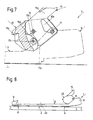
- the bend 4a of the rear part 4 of the base plate and the guide groove 5a of the sole plate 5 can be seen from FIG.
- the rear part 4 of the base plate has a V-shaped horizontal on its area facing away from the offset 4a control curve 4b.
- the sole plate 5 has a front jaw 6 at its front end and a bearing block 8 at its rear end, which is part of a heel holder 7.
- the bearing block 8 is also designed as a spring housing for two compression springs 9, 10.
- the bearing block 8 carries two axes in its front part, namely a transverse axis 11 in its upper region and a pivot axis 12 parallel to the transverse axis 11 in its lower region.
- a sole holder 13 is mounted on the transverse axis 11 and a latching rocker 14 is mounted on the pivot axis 12.
- the sole holder 13, which carries a sole hold-down device 13a and a tris spur 13b at its front end, has a roller-shaped latching element 13c, guide surfaces 13d for a release lever 15 and slots for reaching through for the release lever 15 on the inside.
- the locking rocker 14 which is formed from a first pair of tabs which is articulated in its lower region on the pivot axis 12, carries in its upper region a bolt 16 on which the release lever 15 is pivotably mounted. In its area facing the locking element 13c of the sole holder 13, it has a control cam 14a with a trigger point 14b.
- rocker 17 On the transverse axis 11 a rocker 17 is further articulated, which is formed from a second pair of tabs.
- the rocker 17 When viewed in a side view, the rocker 17 is approximately triangular in shape and has a recess 17a, in which the crosspiece 18a of a first slide 18 is suspended, which is loaded by the first compression spring 9. The crosspiece 18a projects beyond the spring abutment 18b of the first slide 18.
- the rocker 17 is supported on the pivot axis 12.
- Locking arm 14 and rocker 17 are connected to a coupling part 19 consisting of a third pair of straps.
- the coupling part 19 is connected to the rocker arm 17 by means of a pivot pin 20 and by means of a slide pin 21, which slides in an elongated hole 14d of the latch arm 14, to the latch arm 14.
- a locking lever 22, which has a hook 22a, is articulated on the sliding pin 21 and is acted upon in a clockwise direction by a spring 23 fastened to the sliding pin 21 and supported by its first 23a leg from below on the transverse axis 11.
- a closing spring 24 is also attached, which is supported on the one hand on a shoulder 13e of the sole holder 13 and on the other hand on the pivot pin 20.
- a control lever 25 is also mounted on the pivot axis 12 and has in its lower region a roller 26 mounted on an axis, which roller 26 is assigned to the V-shaped horizontal control curve 4b on the rear part 4 of the base plate.
- the control lever 25 is acted upon by the second compression spring 10 by means of a second slide 27, which has an upward driver 27a.
- the first and second compression springs 9, 10 can be pretensioned by means of adjusting screws 28, 29, the adjusting screws 28, 29 being rotatably mounted in the bearing block 8, but secured against axial displacement.
- the spring plates 30, 31 are guided in the bearing block 8 and secured against rotation in a known manner.
- the release lever 15 is approximately U-shaped in front view with two legs 15a. It has two extensions 15b, 15c on each of its legs 15a, which cooperate with the respective guide surface 13d of the sole holder 13. In the closed state of the binding, the upper as well as the lower extensions 15b, 15c are supported on the guide surfaces 13d of the sole holder 13, which lie laterally from the longitudinal center plane. In each of the two legs 15a of the release lever 15 there is an exemption 15d for the transverse axis 11 in the central region.
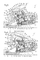
- the sole holder 13 In the event of a frontal fall, the sole holder 13 is pivoted vertically, the latching rocker 14 being pivoted backwards against the force of the first compression spring 9 by the latching element 13c of the sole holder 13, which slides up along the control curve 14a, with the latching rocker 14 and the rocker 17 moving through the rigid coupling behaves like a single piece. If the latching element 13c has exceeded the trigger point 14b (see FIG. 3) of the control curve 14a, it slides along the upper part 14c of the control curve 14a, which is designed such that it allows the first compression spring 9 to relax slightly, which opens the opening force the sole holder 13 delivers against the closing spring 24. After a purely vertical release, the heel holder 7 is ready for entry (Fig. 4)
- the roller 26 moves along the horizontal control curve 4b, as a result of which the control lever 25 is pivoted counterclockwise, which results in the second compression spring 10 being compressed.
- the driver 27a comes into contact with the locking lever 22 and, when pivoted further, takes the locking lever 2 with it until its hook 22a comes out of engagement with the pivoting axis 12 (FIG. 5).
- the coupling between the locking rocker 14 and rocker 17 is released, since the sliding pin 21 dodges upwards.
- the frictional connection from the sole holder 13 to the first compression spring 9 is interrupted, the latching rocker 14 can pivot forcelessly backwards and thus release the latching element 13c upwards, so that the ski boot is released from the heel holder 7 (FIG. 6).
- the sole holder 13 closes due to the closing spring 24.
- the sliding pin 21 is pressed down by the first leg 23a of the spring 23 in the elongated hole 14d and the second leg 23b of the spring 23 presses the hook 22a of the locking lever 22 below the pivot axis 12, whereby the rigid coupling of the locking rocker 14 and rocker 17 is restored.
- the sole holder 13 must be opened with the release lever 15.
- the release lever 15 When the sole holder 13 is opened at will, the release lever 15 is pivoted downward, the lower extensions 15c levering the sole holder 13 up on its guide surfaces 13d.
- the locking element 13c presses the locking rocker 14 against the force of the first compression spring 9 backwards.
- the heel holder 7 In the open state, the heel holder 7 is ready for entry.
- the release lever 15 When the sole holder 13 is closed by hand, the release lever 15 is pivoted upward, the upper extensions 15b acting on guide surfaces 13d of the sole holder 13 downward.
- the triggering should take place with a pure horizontal pivoting first over the front jaws 6 and only then does the heel holder 7 open, in order to prevent the ski boot from sticking to the soleplate 5 when ski boots with a rubber profile sole are used.
- no slide plate is required in the bale area.
- the coordination at which pivot angle the heel holder 7 releases the ski shoe is regulated via the distance between the driver 27a and the hook 22a of the locking lever 22, a larger distance causing the ski shoe to be released later.
Landscapes
- Footwear And Its Accessory, Manufacturing Method And Apparatuses (AREA)
Applications Claiming Priority (2)
| Application Number | Priority Date | Filing Date | Title |
|---|---|---|---|
| AT0010387A AT387153B (de) | 1987-01-21 | 1987-01-21 | Sicherheitsskibindung |
| AT103/87 | 1987-01-21 |
Publications (3)
| Publication Number | Publication Date |
|---|---|
| EP0275380A2 true EP0275380A2 (fr) | 1988-07-27 |
| EP0275380A3 EP0275380A3 (en) | 1990-01-10 |
| EP0275380B1 EP0275380B1 (fr) | 1992-06-24 |
Family
ID=3481592
Family Applications (1)
| Application Number | Title | Priority Date | Filing Date |
|---|---|---|---|
| EP87116272A Expired - Lifetime EP0275380B1 (fr) | 1987-01-21 | 1987-11-05 | Fixation de securité de ski, notamment talonnière |
Country Status (3)
| Country | Link |
|---|---|
| EP (1) | EP0275380B1 (fr) |
| AT (1) | AT387153B (fr) |
| DE (1) | DE3780026D1 (fr) |
Family Cites Families (3)
| Publication number | Priority date | Publication date | Assignee | Title |
|---|---|---|---|---|
| DE2308602A1 (de) * | 1973-02-21 | 1974-08-29 | Marker Hannes | Sicherheits-skibindung |
| DE3102010A1 (de) * | 1981-01-22 | 1982-09-02 | Roland 8100 Garmisch-Partenkirchen Jungkind | "sicherheitsskibindung" |
| DE3342155C2 (de) * | 1983-11-22 | 1995-06-29 | Geze Sport | Sicherheitsskibindung |
-
1987
- 1987-01-21 AT AT0010387A patent/AT387153B/de not_active IP Right Cessation
- 1987-11-05 DE DE8787116272T patent/DE3780026D1/de not_active Expired - Lifetime
- 1987-11-05 EP EP87116272A patent/EP0275380B1/fr not_active Expired - Lifetime
Also Published As
| Publication number | Publication date |
|---|---|
| AT387153B (de) | 1988-12-12 |
| ATA10387A (de) | 1988-05-15 |
| EP0275380B1 (fr) | 1992-06-24 |
| DE3780026D1 (de) | 1992-07-30 |
| EP0275380A3 (en) | 1990-01-10 |
Similar Documents
| Publication | Publication Date | Title |
|---|---|---|
| EP0069753B1 (fr) | Fixation de securite de ski | |
| EP0200044B1 (fr) | Butée avant pour fixations de sécurité de ski | |
| DE1703054C3 (de) | Sicherheits-Skibindung | |
| CH673401A5 (fr) | ||
| DE102016013104A1 (de) | Skibindung | |
| DE69401171T2 (de) | Bindungselement für einen alpinen Ski | |
| DE1910808B2 (de) | Vorderbacken für Sicherheitsskibindungen | |
| EP0264436B1 (fr) | Fixation de securite pour skis, en particulier fixation du talon | |
| DE4124046A1 (de) | Langlaufskibindung | |
| DE3905445A1 (de) | Vorderbacken fuer sicherheitsskibindungen | |
| EP0275380B1 (fr) | Fixation de securité de ski, notamment talonnière | |
| DE3202267A1 (de) | Fersenhalter einer skibindung mit skibremse | |
| DE2356908A1 (de) | Sicherheits-skibindung | |
| DE3421499A1 (de) | Sicherheitsskibindung | |
| EP0128243B1 (fr) | Fixation de ski à déclenchement | |
| DE2637871B2 (de) | Sicherheiteskibindung | |
| DE1930997A1 (de) | Vorderbacken fuer Sicherheits-Skibindungen | |
| DE1703915A1 (de) | Absatzhaltevorrichtung fuer Sicherheits-Skibindungen | |
| AT402022B (de) | Sicherheitsskibindung | |
| EP0202440B1 (fr) | Mâchoire de sécurité pour fixation de ski | |
| DE4030816A1 (de) | Fersenhalterung einer sicherheitsskibindung | |
| CH617594A5 (fr) | ||
| DE4203569A1 (de) | Sicherheitsvorderbacken einer skibindung | |
| DE2429610A1 (de) | Sicherheitsskibindung | |
| DE2907364A1 (de) | Langlauf-sicherheitsskibindung |
Legal Events
| Date | Code | Title | Description |
|---|---|---|---|
| PUAI | Public reference made under article 153(3) epc to a published international application that has entered the european phase |
Free format text: ORIGINAL CODE: 0009012 |
|
| AK | Designated contracting states |
Kind code of ref document: A2 Designated state(s): CH DE FR LI |
|
| PUAL | Search report despatched |
Free format text: ORIGINAL CODE: 0009013 |
|
| AK | Designated contracting states |
Kind code of ref document: A3 Designated state(s): CH DE FR LI |
|
| 17P | Request for examination filed |
Effective date: 19900514 |
|
| 17Q | First examination report despatched |
Effective date: 19910830 |
|
| RAP1 | Party data changed (applicant data changed or rights of an application transferred) |
Owner name: TMC CORPORATION |
|
| GRAA | (expected) grant |
Free format text: ORIGINAL CODE: 0009210 |
|
| AK | Designated contracting states |
Kind code of ref document: B1 Designated state(s): CH DE FR LI |
|
| REF | Corresponds to: |
Ref document number: 3780026 Country of ref document: DE Date of ref document: 19920730 |
|
| ET | Fr: translation filed | ||
| REG | Reference to a national code |
Ref country code: CH Ref legal event code: PUE Owner name: HTM SPORT- UND FREIZEITGERAETE GMBH |
|
| RAP2 | Party data changed (patent owner data changed or rights of a patent transferred) |
Owner name: HTM SPORT- UND FREIZEITGERAETE GESELLSCHAFT M.B.H. |
|
| PLBE | No opposition filed within time limit |
Free format text: ORIGINAL CODE: 0009261 |
|
| STAA | Information on the status of an ep patent application or granted ep patent |
Free format text: STATUS: NO OPPOSITION FILED WITHIN TIME LIMIT |
|
| 26N | No opposition filed | ||
| PGFP | Annual fee paid to national office [announced via postgrant information from national office to epo] |
Ref country code: FR Payment date: 19930917 Year of fee payment: 7 |
|
| PGFP | Annual fee paid to national office [announced via postgrant information from national office to epo] |
Ref country code: DE Payment date: 19930921 Year of fee payment: 7 |
|
| PGFP | Annual fee paid to national office [announced via postgrant information from national office to epo] |
Ref country code: CH Payment date: 19931109 Year of fee payment: 7 |
|
| REG | Reference to a national code |
Ref country code: CH Ref legal event code: PFA Free format text: HTM SPORT- UND FREIZEITGERAETE AKTIENGESELLSCHAFT |
|
| PG25 | Lapsed in a contracting state [announced via postgrant information from national office to epo] |
Ref country code: LI Effective date: 19941130 Ref country code: CH Effective date: 19941130 |
|
| PG25 | Lapsed in a contracting state [announced via postgrant information from national office to epo] |
Ref country code: FR Effective date: 19950731 |
|
| REG | Reference to a national code |
Ref country code: CH Ref legal event code: PL |
|
| PG25 | Lapsed in a contracting state [announced via postgrant information from national office to epo] |
Ref country code: DE Effective date: 19950801 |
|
| REG | Reference to a national code |
Ref country code: FR Ref legal event code: ST |