EP0274470B1 - Vorrichtung zum befüllen von transportablen behältern mit fliessfähigen stoffen - Google Patents
Vorrichtung zum befüllen von transportablen behältern mit fliessfähigen stoffen Download PDFInfo
- Publication number
- EP0274470B1 EP0274470B1 EP86905273A EP86905273A EP0274470B1 EP 0274470 B1 EP0274470 B1 EP 0274470B1 EP 86905273 A EP86905273 A EP 86905273A EP 86905273 A EP86905273 A EP 86905273A EP 0274470 B1 EP0274470 B1 EP 0274470B1
- Authority
- EP
- European Patent Office
- Prior art keywords
- clamping ring
- connexion
- cylindrical
- piece
- annular disk
- Prior art date
- Legal status (The legal status is an assumption and is not a legal conclusion. Google has not performed a legal analysis and makes no representation as to the accuracy of the status listed.)
- Expired - Lifetime
Links
- 239000000463 material Substances 0.000 title claims abstract description 5
- 239000000945 filler Substances 0.000 claims abstract description 15
- 230000009969 flowable effect Effects 0.000 claims description 4
- 239000007788 liquid Substances 0.000 description 6
- 238000003860 storage Methods 0.000 description 5
- 239000000126 substance Substances 0.000 description 4
- 230000002787 reinforcement Effects 0.000 description 2
- 239000012080 ambient air Substances 0.000 description 1
- 230000009189 diving Effects 0.000 description 1
- 238000010410 dusting Methods 0.000 description 1
- 238000005429 filling process Methods 0.000 description 1
- 238000007654 immersion Methods 0.000 description 1
- 238000004519 manufacturing process Methods 0.000 description 1
- 238000000034 method Methods 0.000 description 1
- 230000029058 respiratory gaseous exchange Effects 0.000 description 1
- 238000003756 stirring Methods 0.000 description 1
Images

Classifications
-
- B—PERFORMING OPERATIONS; TRANSPORTING
- B65—CONVEYING; PACKING; STORING; HANDLING THIN OR FILAMENTARY MATERIAL
- B65D—CONTAINERS FOR STORAGE OR TRANSPORT OF ARTICLES OR MATERIALS, e.g. BAGS, BARRELS, BOTTLES, BOXES, CANS, CARTONS, CRATES, DRUMS, JARS, TANKS, HOPPERS, FORWARDING CONTAINERS; ACCESSORIES, CLOSURES, OR FITTINGS THEREFOR; PACKAGING ELEMENTS; PACKAGES
- B65D88/00—Large containers
- B65D88/54—Large containers characterised by means facilitating filling or emptying
Definitions
- the invention relates to a device for filling portable containers according to the preamble of the main claim.
- the invention has for its object to provide a connection system between a transportable container and a central filling station, which has a flexible filling hose, which can be adjusted in the vertical and horizontal directions to the position of the transportable container to the delivery point of the storage container, but without this Outside of the filling hose ever comes into contact with the filling material.
- the invention proposes a flexible filling hose which connects at both ends to clamping rings and which is folded back on itself, a weighting ring being provided in the lower turning area, so that the filling hose always has a correct, downward position is guaranteed, with changes in the height of the filling hose now being possible without the outside of the filling hose coming into contact with the free ambient air.
- a protrusion of the filling hose into the transportable container is reduced by half, so that when stirring units such as paddles or the like are arranged in the transportable container, the filling hose does not come into contact with these paddle devices.
- the filling hose can be transported with the flexible container and dips, for example, with its lower end under the liquid level of the portable container, so that only the liquid level located within the filling hose cross-section is breathingly connected to the atmosphere outside the container. This enormously reduces the emissions of flammable liquids.
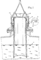
- 1 denotes a transportable container, which has a filler neck 2 on its top.
- a first clamping ring 3 is connected to this filler neck 2 and fixed, for example, via corresponding hook closures 4.
- the first clamping ring 3 consists of an annular disc 5 with a central opening, to which an upwardly directed cylinder connector 6 connects.
- the lower free end of a flexible filling hose 8 is fixed on the outside of this cylinder connector with the interposition of a clamp 7, which is folded back on itself and led upwards, so that it creates a turning area 9 in the lower area.
- a reinforcement ring 10 is arranged, which preferably consists of a round support unit, for example a wire or the like, on which rotatable spherical bodies are arranged, so that when the length of the flexible filling hose 8 changes, this reinforcement ring 10 moves can easily follow the hose.
- the opposite upper end of the filling hose 8 is attached to a second clamping ring 11.
- This second clamping ring 11 consists of an annular disc 12 with an upwardly directed cylinder connector 14, on the outside thereof.
- the flexible filling hose 8 is fixed via a clamp 15.
- a second cylinder connector 16 connects, which has an inner diameter. has, which is larger than the outer diameter of the cylinder neck 14.
- the inner diameter of the cylinder neck 16 is larger than the outer diameter of the cylinder neck 6 of the first clamping ring 3. This allows nesting of the second clamping ring 11 on the first clamping ring 3.
- Support bearings 17 are arranged on the outside of the second cylinder stub 16 and the partial illustration in FIG. 2 shows that by appropriately designing the wall of the outflow opening of the actual storage container, in FIG. 2 this outflow opening is generally designated 18, a placement of these support bearings 17 on corresponding support brackets 19 is possible.
- the second clamping ring 11 can be fixed in the region of the outflow opening 18, the connection between the filling funnel 20 shown in FIG. 2 and the actual filler neck 2 of the container 1 now being made through the flexible filling hose 8.
- the annular disk 12 has projecting retaining lugs 21 over the outer circumference of the second cylinder connector 16, which - as shown in the detail in FIG. 1 - can be inserted into corresponding recesses 22 in a cover hood 23, as a result of which - as clearly shown in FIG. 1 - a bayonet-type locking between the second clamping ring 11 and the cover 23 takes place.
- the cover hood 23 has a cylinder wall 24 in which the recesses 22 are provided and which engages over the annular disk 12.
- Handle eyelets 25 are arranged on the top of the cover hood 23, by means of which crane-operated handling of the cover hood 23 is possible.
- the flexible filling hose 8 can be lowered into the container through the filler neck 2 of the container 1, the immersion length of the flexible filling hose 8 being only half of its total length .
- the flexible filling hose 8 immersed under the liquid level S shown in FIG. 1 ends with its lower end above the mixing paddle moved in the transportable container, so that mixing can also be carried out when the filling hose and the covered filler neck 2 are suspended.
- the flexible filling hose immersed under the liquid level S only the liquid level located within the filling hose cross section is brought into breathing contact with the atmosphere outside the container, so that the emissions are thereby considerably reduced.
Landscapes
- Engineering & Computer Science (AREA)
- Mechanical Engineering (AREA)
- Basic Packing Technique (AREA)
- Supply Of Fluid Materials To The Packaging Location (AREA)
- Supplying Of Containers To The Packaging Station (AREA)
Description
- Die Erfindung bezieht sich auf eine Vorrichtung zum Befüllen von transportablen Behältern gemäß dem Oberbegriff des Hauptanspruches.
- Das Befüllen von Behältern mit fließfähigen Stoffen im freien Fall ist besonders in innerbetrieblichen Einrichtungen erforderlich, um schnell die für die Fabrikation erforderlichen Stoffe aus einer zentralen Lagerstelle zu den einzelnen Verarbeitungsstellen führen zu können. Auch bei anderen großen Transporteinrichtungen, beispielsweise in der landwirtschaftlichen Futtermittelindustrie, ist das Füllen von transportablen Behältern im freien Fall aus einem Vorratsbehälter notwendig. Wichtig ist bei solche Anlagen, daß der freifallende, fließfähige Stoff durch geeignete Schläuche geführt wird, um damit ein Spritzen, Stauben und vagabundierende Emissionen zu vermeiden. Schwierig bei den bekannten Anlagen ist die genaue Höheneinregulierung zwischen der Abgabestelle aus dem Vorratslager und dem Einfüllstutzen des transportablen Behälters, wobei beim Einsatz flexibler Schläuche verhindert werden muß, daß die Außenseite des Schlauches mit dem geführten Gut in Kontakt kommt, so daß damit die Handhabbarkeit des Füllschlauches ermöglicht und Umweltverschmutzungen vermieden werden.
- Der Erfindung liegt die Aufgabe zugrunde, ein Verbindungssystem zwischen einem transportablen Behälter und einer zentralen Füllstation zu schaffen, das einen flexiblen Füllschlauch aufweist, der in vertikaler und horizontaler Richtung an die Lage des transportablen Behälters zur Abgabestelle des Vorratsbehälters einregulierbar ist, ohne daß dabei aber die Außenseite des Füllschlauches jemals mit Füllgut in Kontakt kommt.
- Diese der Erfindung zugrundeliegende Aufgabe wird durch die Lehre des Hauptanspruches gelöst.
- Vorteilhafte Ausgestaltungen sind in den Unteransprüchen erläutert.
- Mit anderen Worten ausgedrückt schlägt die Erfindung einen flexiblen Füllschlauch vor, der an seinen beiden Enden an Klemmringe anschließt und der auf sich selbst zurückgefaltet ist, wobei in dem unteren Wendebereich ein Beschwerungsring vorgesehen ist, so daß stets eine korrekte, nach unten gerichtete Lage des Füllschlauches gewährleistet wird, wobei nunmehr Höhenänderungen des Füllschlauches möglich sind, ohne daß die Außenseite des Füllschlauches mit der freien Umgebungsluft in Verbindung kommt. Außerdem wird ein Hineinragen des Füllschlauches in den transportablen Behälter um die Hälfte verringert, so daß, wenn in dem transportablen Behälter Rühraggregate, wie Paddel od. dgl., angeordnet sind, der Füllschlauch mit diesen Paddeleinrichtungen nicht in Kontakt kommt.
- Der Füllschlauch kann dabei mit dem flexiblen Behälter transportiert werden und taucht beispielsweise mit seinem unteren Ende unter den Flüssigkeitsspiegel des transportablen Behälters ein, so daß nur der innerhalb des Füllschlauchquerschnittes befindliche Flüssigkeitsspiegel atmend mit der Atmosphäre außerhalb des Behälters in Verbindung steht. Hierdurch werden Emissionen von brennbaren Flüssigkeiten enorm reduziert.
- Ein Ausführungsbeispiel der Erfindung wird nachfolgend anhand der Zeichnungen erläutert. Die Zeichnungen zeigen dabei in
- Fig. 1 eine Teilansicht auf einen transportablen Behälter mit aufgesetztem Füllschlauch und diesen verschließenden Deckel und in
- Fig. 2 den Füllschlauch gemäß Fig. 1 im ausgezogenen Zustand im Anschluß an eine Abgabeöffnung für die zu transportierenden fließfähigen Stoffe.
- In den Zeichnungen ist mit 1 ein transportabler Behälter bezeichnet, der einen Einfüllstutzen 2 an seiner Oberseite aufweist. An diesen Einfüllstutzen 2 ist ein erster Klemmring 3 angeschlossen und beispielsweise über entsprechende Hakenverschlüsse 4 festgelegt. Der erste Klemmring 3 besteht aus einer Ringscheibe 5 mit einer zentralen Öffnung, an die sich ein nach oben gerichteter Zylinderstutzen 6 anschließt. An der Außenseite dieses Zylinderstutzens ist unter Zwischenschaltung einer Klemmschelle 7 das untere freie Ende eines flexiblen Füllschlauches 8 festgelegt, der auf sich selbst zurückgefaltet nach oben geführt ist, so daß er im unteren Bereich einen Wendebereich 9 schafft. In dem durch diesen Wendebereich 9 geschaffenen Ringraum ist ein Bewehrungsring 10 angeordnet, der vorzugsweise aus einem runden Trägeraggregat besteht, beispielsweise einem Draht od. dgl., auf dem drehbar Kugelkörper angeordnet sind, so daß bei Längenänderungen des flexiblen Füllschlauches 8 dieser Bewehrungsring 10 den Bewegungen des Schlauches leicht folgen kann.
- Das entgegengesetzte obere Ende des Füllschlauches 8 ist an einem zweiten Klemmring 11 befestigt. Dieser zweite Klemmring 11 besteht aus einer Ringscheibe 12 mit einem nach oben gerichteten Zylinderstutzen 14, auf dessen Außenseite . der flexible Füllschlauch 8 über eine Klemmschelle 15 festgelegt ist. An die Unterseite der Ringscheibe 12 schließt ein zweiter Zylinderstutzen 16 an, der einen Innendurchmesser. aufweist, der größer als der Außendurchmesser des Zylinderstutzens 14 ist. Außerdem ist der Innendurchmesser des Zylinderstutzens 16 größer als der Außendurchmesser des Zylinderstutzens 6 des ersten Klemmringes 3. Hierdurch ist ein Ineinanderschachteln des zweiten Klemmringes 11 auf den ersten Klemmring 3 möglich.
- An der Außenseite des zweiten Zylinderstutzens 16 sind Stützlager 17 angeordnet und die Teildarstellung in Fig. 2 zeigt, daß durch entsprechende Ausbildung der Wandung der Ausflußöffnung des eigentlichen Vorratsbehälters, wobei in Fig. 2 diese Ausflußöffnung allgemein mit 18 bezeichnet ist, ein Aufsetzen dieser Stützlager 17 auf entsprechenden Stützböcken 19 möglich wird. Hierdurch kann der zweite Klemmring 11 im Bereich der Ausflußöffnung 18 festgesetzt werden, wobei die Verbindung zwischen dem in Fig. 2 dargestellten Fülltrichter 20 und dem eigentlichen Einfüllstutzen 2 des Behälters 1 nunmehr durch den flexiblen Füllschlauch 8 erfolgt.
- Die Ringscheibe 12 weist über den Außenumfang des zweiten Zylinderstutzens 16 vorstehende Haltenasen 21 auf, die - wie dies die Ausschnittsdarstellung in Fig. 1 zeigt - in entsprechende Ausnehmungen 22 einer Deckelhaube 23 eingesetzt werden können, wodurch - wie dies deutlich die Fig. 1 zeigt - ein bajonettverschlußartiges Verriegeln zwischen dem zweiten Klemmring 11 und der Deckelhaube 23 erfolgt.
- Die Deckelhaube 23 weist eine Zylinderwand 24 auf, in der die Ausnehmungen 22 vorgesehen sind und die die Ringscheibe 12 übergreift. An der Oberseite der Deckelhaube 23 sind Griffösen 25 angeordnet, durch die eine kranbetätigte Handhabung der Deckelhaube 23 möglich wird.
- Aus der Darstellung in Fig. 1 ist erkennbar, daß nach Beendigung des Füllvorganges des transportablen Behälters 1 der flexible Füllschlauch 8 durch den Einfüllstutzen 2 des Behälters 1 in den Behälter abgesenkt werden kann, wobei die Eintauchlänge des flexiblen Füllschlauches 8 nur die Hälfte seiner Gesamtlänge beträgt. Hierdurch endet der unter den in Fig. 1 eingezeichneten Flüssigkeitsspiegel S eintauchende flexible Füllschlauch 8 mit seinem unteren Ende oberhalb des in dem transportablen Behälter bewegten Mischpaddels, so daß bei eingehängtem Füllschlauch und abgedecktem Einfüllstutzen 2 auch gemischt werden kann. Weiterhin wird durch den unter den Flüssigkeitsspiegel S eintauchenden flexiblen Füllschlauch nur der innerhalb des Füllschlauchquerschnittes befindliche Flüssigkeitsspiegel atmend mit der Atmosphäre außerhalb des Behälters in Verbindung gebracht, so daß dadurch die Emissionen erheblich verringert werden.
- Durch das Wenden des flexiblen Füllschlauches 8 wird sichergestellt, daß sowohl im eingespannten Zustand beim Befüllen, als auch im gewendeten und getauchten Zustand beim Transport und Mischen nur die Füllschlauchinnenseite mit den einzufüllenden Stoffen in Kontakt kommt und somit der Füllschlauch selbst sich bei wiederholendem Befüll- und Tauchvorgang außen sauber und handhabbar bleibt.
- Durch den Einsatz des flexiblen Füllschlauches 8 können Positionierunterschiede sowohl in der Höhe wie in der Seite des Einfüllstutzens 2 gegenüber der Ausflußöffnung 18 ausgeglichen werden.
Claims (9)
Priority Applications (1)
| Application Number | Priority Date | Filing Date | Title |
|---|---|---|---|
| AT86905273T ATE51375T1 (de) | 1985-09-23 | 1986-08-21 | Vorrichtung zum befuellen von transportablen behaeltern mit fliessfaehigen stoffen. |
Applications Claiming Priority (2)
| Application Number | Priority Date | Filing Date | Title |
|---|---|---|---|
| DE3533837A DE3533837C1 (de) | 1985-09-23 | 1985-09-23 | Vorrichtung zum Befuellen von transportablen Behaeltern mit fliessfaehigen Stoffen |
| DE3533837 | 1985-09-23 |
Publications (2)
| Publication Number | Publication Date |
|---|---|
| EP0274470A1 EP0274470A1 (de) | 1988-07-20 |
| EP0274470B1 true EP0274470B1 (de) | 1990-03-28 |
Family
ID=6281672
Family Applications (1)
| Application Number | Title | Priority Date | Filing Date |
|---|---|---|---|
| EP86905273A Expired - Lifetime EP0274470B1 (de) | 1985-09-23 | 1986-08-21 | Vorrichtung zum befüllen von transportablen behältern mit fliessfähigen stoffen |
Country Status (7)
| Country | Link |
|---|---|
| US (1) | US4817690A (de) |
| EP (1) | EP0274470B1 (de) |
| BR (1) | BR8607186A (de) |
| CA (1) | CA1267870A (de) |
| DE (2) | DE3533837C1 (de) |
| ES (1) | ES2002368A6 (de) |
| WO (1) | WO1987001681A1 (de) |
Families Citing this family (4)
| Publication number | Priority date | Publication date | Assignee | Title |
|---|---|---|---|---|
| FR2696725B1 (fr) * | 1992-10-09 | 1995-01-20 | Cellier | Installation de transfert non contaminante pour matière granuleuse ou pulvérulente entre deux enceintes physiquement séparées. |
| FR2696727A1 (fr) * | 1992-10-09 | 1994-04-15 | Cellier | Installation de transfert en milieu contrôlé, de produits fragiles sous forme unitaire et transportés en vrac. |
| FR2696726B1 (fr) * | 1992-10-09 | 1995-01-20 | Cellier | Installation de chargement, en matière granuleuse ou pulvérulente, d'un conteneur de transfert entre deux enceintes physiquement séparées. |
| US5636799A (en) * | 1995-01-13 | 1997-06-10 | Clark Equipment Company | Frame mounted isolated motor driven electrostatic spray system |
Family Cites Families (11)
| Publication number | Priority date | Publication date | Assignee | Title |
|---|---|---|---|---|
| SE346224B (de) * | 1970-11-03 | 1972-07-03 | Trelleborgs Gummifabriks Ab | |
| US3738464A (en) * | 1972-05-17 | 1973-06-12 | E Ortlip | Drop boot to prevent wind loss of finely divided fluent materials |
| DE2824949A1 (de) * | 1978-06-07 | 1979-12-20 | Hansaliv Gurte Gmbh & Co Kg | Vorrichtung zum befuellen von flexiblen behaeltern |
| GB2029378B (en) * | 1978-09-05 | 1982-09-08 | British Nuclear Fuels Ltd | Transferring material between hoppers or containers |
| FR2456277A1 (fr) * | 1979-05-07 | 1980-12-05 | Kleber Colombes | Dispositif de mise en communication d'un reservoir avec un autre reservoir ou une tubulure rigide |
| US4256154A (en) * | 1979-07-09 | 1981-03-17 | Steven Black | Bottle with retractable funnel top |
| US4296502A (en) * | 1980-03-17 | 1981-10-27 | Bonnie Bortle | Self-packaging urine conduit |
| US4640313A (en) * | 1983-12-19 | 1987-02-03 | Stanley Robert K | Interlining of pipelines for transporting sewage, water, slurries, liquid and gaseous hydrocarbons, and the like |
| US4632282A (en) * | 1984-03-02 | 1986-12-30 | Hirohisa Nagashima | Spout assembly |
| US4589578A (en) * | 1984-03-07 | 1986-05-20 | Hayward Patrick K | Container with improved disposable pouring spout |
| DE3424613A1 (de) * | 1984-07-04 | 1986-01-16 | Günther 8068 Pfaffenhofen Hecht | Vorrichtung zum befuellen flexibler schuettgutbehaelter |
-
1985
- 1985-09-23 DE DE3533837A patent/DE3533837C1/de not_active Expired
-
1986
- 1986-08-21 BR BR8607186A patent/BR8607186A/pt not_active IP Right Cessation
- 1986-08-21 WO PCT/EP1986/000490 patent/WO1987001681A1/de not_active Ceased
- 1986-08-21 DE DE8686905273T patent/DE3669860D1/de not_active Expired - Lifetime
- 1986-08-21 EP EP86905273A patent/EP0274470B1/de not_active Expired - Lifetime
- 1986-08-21 US US07/075,814 patent/US4817690A/en not_active Expired - Fee Related
- 1986-09-23 CA CA000518864A patent/CA1267870A/en not_active Expired - Lifetime
- 1986-09-23 ES ES8602098A patent/ES2002368A6/es not_active Expired
Also Published As
| Publication number | Publication date |
|---|---|
| WO1987001681A1 (fr) | 1987-03-26 |
| DE3533837C1 (de) | 1987-01-29 |
| CA1267870A (en) | 1990-04-17 |
| US4817690A (en) | 1989-04-04 |
| BR8607186A (pt) | 1988-09-13 |
| DE3669860D1 (de) | 1990-05-03 |
| ES2002368A6 (es) | 1988-08-01 |
| EP0274470A1 (de) | 1988-07-20 |
Similar Documents
| Publication | Publication Date | Title |
|---|---|---|
| DE2731980C2 (de) | Vorrichtung zum Ausspeisen von flüssigen oder pastösen Erzeugnisse | |
| DE1939086C3 (de) | Behälter zur Aufbewahrung und zum Ansetzen einer mindestens eine zu lösende Komponente enthaltenden Flüssigkeit | |
| DE3136669C2 (de) | Behälter zum Aufbewahren und Servieren von Lebensmitteln | |
| DE2350825A1 (de) | Vorrichtung zur aufbewahrung und abgabe von fluessigkeit | |
| WO1987001681A1 (fr) | Dispositif pour remplir les recipients transportables de materiaux coulants | |
| DE2623665B2 (de) | Verfahren und Vorrichtung zum Reinigen eines in der Achse eines vorzugsweise zylindrischen Behälters angeordnetem, um diese Achse drehbaren Rührwerks | |
| DE3126668A1 (de) | Auslaufeinrichtung eines behaelters fuer staubfoermiges oder koerniges schuettgut | |
| DE4436003C2 (de) | Vorrichtung zum Entsorgen von flüssigen Medien | |
| EP0585596A1 (de) | Presse zum Auspressen von flüssigkeitshaltigen Stoffen | |
| DE2108380A1 (de) | Beschickungsvorrichtung fur Behal ter großen Querschnitts | |
| DE19536549A1 (de) | Verfahren und Vorrichtung zur Beschickung und Entleerung eines Schüttgutbehälters | |
| DE224262C (de) | ||
| DE10157800A1 (de) | Verfahren und Vorrichtung zum Entleeren eines Verpackungsgebindes | |
| DE3719530C2 (de) | Belüftungsdüse | |
| DE2455342C3 (de) | Zum Aufsetzen auf einen Behälter für pulverförmiges Material bestimmte VerschluBvorrichtung | |
| DE2033670C3 (de) | Entleerungshilfsvorrichtung für Transport- oder Lagerbehälter | |
| DE4403708A1 (de) | Vorrichtung zur pneumatischen Beschickung einer Maschine, insbesondere Putzmaschine, mit feinkörnigen Stoffen | |
| DE3104285C2 (de) | Vorrichtung zur Aufnahme, zum Mischen und zum Transport von viskosen Flüssigkeiten | |
| DE2231584A1 (de) | Transportsilo fuer pulverfoermiges gut | |
| DE4100742A1 (de) | Ausgiesshilfe fuer kanister in form eines belueftungsrohres | |
| EP3188588B1 (de) | Halte- und/oder fördersystem | |
| DE3910203A1 (de) | Filteranordnung fuer grossbehaelter | |
| DE1251212B (de) | Flexibler Transportbehälter mit Tragvorrichtung | |
| DE20002392U1 (de) | Vorrichtung zum Belüften von Flüssigkeiten in über eine Öffnung zugänglichen Behältern | |
| DE2950037C2 (de) | Vorrichtung zum Füllen von Flaschen mit Flüssigkeiten |
Legal Events
| Date | Code | Title | Description |
|---|---|---|---|
| PUAI | Public reference made under article 153(3) epc to a published international application that has entered the european phase |
Free format text: ORIGINAL CODE: 0009012 |
|
| 17P | Request for examination filed |
Effective date: 19880111 |
|
| AK | Designated contracting states |
Kind code of ref document: A1 Designated state(s): AT BE CH DE FR GB IT LI NL SE |
|
| 17Q | First examination report despatched |
Effective date: 19890830 |
|
| GRAA | (expected) grant |
Free format text: ORIGINAL CODE: 0009210 |
|
| AK | Designated contracting states |
Kind code of ref document: B1 Designated state(s): AT BE CH DE FR GB IT LI NL SE |
|
| REF | Corresponds to: |
Ref document number: 51375 Country of ref document: AT Date of ref document: 19900415 Kind code of ref document: T |
|
| GBT | Gb: translation of ep patent filed (gb section 77(6)(a)/1977) | ||
| REF | Corresponds to: |
Ref document number: 3669860 Country of ref document: DE Date of ref document: 19900503 |
|
| ET | Fr: translation filed | ||
| ITF | It: translation for a ep patent filed | ||
| PLBE | No opposition filed within time limit |
Free format text: ORIGINAL CODE: 0009261 |
|
| STAA | Information on the status of an ep patent application or granted ep patent |
Free format text: STATUS: NO OPPOSITION FILED WITHIN TIME LIMIT |
|
| 26N | No opposition filed | ||
| ITTA | It: last paid annual fee | ||
| EAL | Se: european patent in force in sweden |
Ref document number: 86905273.8 |
|
| PGFP | Annual fee paid to national office [announced via postgrant information from national office to epo] |
Ref country code: GB Payment date: 19980723 Year of fee payment: 13 |
|
| PGFP | Annual fee paid to national office [announced via postgrant information from national office to epo] |
Ref country code: AT Payment date: 19980727 Year of fee payment: 13 |
|
| PGFP | Annual fee paid to national office [announced via postgrant information from national office to epo] |
Ref country code: FR Payment date: 19980813 Year of fee payment: 13 |
|
| PGFP | Annual fee paid to national office [announced via postgrant information from national office to epo] |
Ref country code: SE Payment date: 19980820 Year of fee payment: 13 Ref country code: BE Payment date: 19980820 Year of fee payment: 13 |
|
| PGFP | Annual fee paid to national office [announced via postgrant information from national office to epo] |
Ref country code: NL Payment date: 19980825 Year of fee payment: 13 |
|
| PGFP | Annual fee paid to national office [announced via postgrant information from national office to epo] |
Ref country code: CH Payment date: 19980923 Year of fee payment: 13 |
|
| PGFP | Annual fee paid to national office [announced via postgrant information from national office to epo] |
Ref country code: DE Payment date: 19980929 Year of fee payment: 13 |
|
| PG25 | Lapsed in a contracting state [announced via postgrant information from national office to epo] |
Ref country code: GB Free format text: LAPSE BECAUSE OF NON-PAYMENT OF DUE FEES Effective date: 19990821 Ref country code: AT Free format text: LAPSE BECAUSE OF NON-PAYMENT OF DUE FEES Effective date: 19990821 |
|
| PG25 | Lapsed in a contracting state [announced via postgrant information from national office to epo] |
Ref country code: SE Free format text: THE PATENT HAS BEEN ANNULLED BY A DECISION OF A NATIONAL AUTHORITY Effective date: 19990830 |
|
| PG25 | Lapsed in a contracting state [announced via postgrant information from national office to epo] |
Ref country code: LI Free format text: LAPSE BECAUSE OF NON-PAYMENT OF DUE FEES Effective date: 19990831 Ref country code: CH Free format text: LAPSE BECAUSE OF NON-PAYMENT OF DUE FEES Effective date: 19990831 Ref country code: BE Free format text: LAPSE BECAUSE OF NON-PAYMENT OF DUE FEES Effective date: 19990831 |
|
| BERE | Be: lapsed |
Owner name: BASF LACKE + FARBEN A.G. Effective date: 19990831 |
|
| PG25 | Lapsed in a contracting state [announced via postgrant information from national office to epo] |
Ref country code: NL Free format text: LAPSE BECAUSE OF NON-PAYMENT OF DUE FEES Effective date: 20000301 |
|
| GBPC | Gb: european patent ceased through non-payment of renewal fee |
Effective date: 19990821 |
|
| REG | Reference to a national code |
Ref country code: CH Ref legal event code: PL |
|
| PG25 | Lapsed in a contracting state [announced via postgrant information from national office to epo] |
Ref country code: FR Free format text: LAPSE BECAUSE OF NON-PAYMENT OF DUE FEES Effective date: 20000428 |
|
| EUG | Se: european patent has lapsed |
Ref document number: 86905273.8 |
|
| NLV4 | Nl: lapsed or anulled due to non-payment of the annual fee |
Effective date: 20000301 |
|
| PG25 | Lapsed in a contracting state [announced via postgrant information from national office to epo] |
Ref country code: DE Free format text: LAPSE BECAUSE OF NON-PAYMENT OF DUE FEES Effective date: 20000601 |
|
| REG | Reference to a national code |
Ref country code: FR Ref legal event code: ST |
|
| PG25 | Lapsed in a contracting state [announced via postgrant information from national office to epo] |
Ref country code: IT Free format text: LAPSE BECAUSE OF NON-PAYMENT OF DUE FEES;WARNING: LAPSES OF ITALIAN PATENTS WITH EFFECTIVE DATE BEFORE 2007 MAY HAVE OCCURRED AT ANY TIME BEFORE 2007. THE CORRECT EFFECTIVE DATE MAY BE DIFFERENT FROM THE ONE RECORDED. Effective date: 20050821 |