EP0272130A2 - Enregistrement de données - Google Patents
Enregistrement de données Download PDFInfo
- Publication number
- EP0272130A2 EP0272130A2 EP87311151A EP87311151A EP0272130A2 EP 0272130 A2 EP0272130 A2 EP 0272130A2 EP 87311151 A EP87311151 A EP 87311151A EP 87311151 A EP87311151 A EP 87311151A EP 0272130 A2 EP0272130 A2 EP 0272130A2
- Authority
- EP
- European Patent Office
- Prior art keywords
- recording
- data
- signal
- recorded
- heads
- Prior art date
- Legal status (The legal status is an assumption and is not a legal conclusion. Google has not performed a legal analysis and makes no representation as to the accuracy of the status listed.)
- Granted
Links
Images


Classifications
-
- G—PHYSICS
- G11—INFORMATION STORAGE
- G11B—INFORMATION STORAGE BASED ON RELATIVE MOVEMENT BETWEEN RECORD CARRIER AND TRANSDUCER
- G11B20/00—Signal processing not specific to the method of recording or reproducing; Circuits therefor
- G11B20/10—Digital recording or reproducing
-
- G—PHYSICS
- G11—INFORMATION STORAGE
- G11B—INFORMATION STORAGE BASED ON RELATIVE MOVEMENT BETWEEN RECORD CARRIER AND TRANSDUCER
- G11B20/00—Signal processing not specific to the method of recording or reproducing; Circuits therefor
- G11B20/10—Digital recording or reproducing
- G11B20/18—Error detection or correction; Testing, e.g. of drop-outs
- G11B20/1883—Methods for assignment of alternate areas for defective areas
-
- G—PHYSICS
- G11—INFORMATION STORAGE
- G11B—INFORMATION STORAGE BASED ON RELATIVE MOVEMENT BETWEEN RECORD CARRIER AND TRANSDUCER
- G11B15/00—Driving, starting or stopping record carriers of filamentary or web form; Driving both such record carriers and heads; Guiding such record carriers or containers therefor; Control thereof; Control of operating function
- G11B15/02—Control of operating function, e.g. switching from recording to reproducing
- G11B15/05—Control of operating function, e.g. switching from recording to reproducing by sensing features present on or derived from record carrier or container
- G11B15/087—Control of operating function, e.g. switching from recording to reproducing by sensing features present on or derived from record carrier or container by sensing recorded signals
-
- G—PHYSICS
- G11—INFORMATION STORAGE
- G11B—INFORMATION STORAGE BASED ON RELATIVE MOVEMENT BETWEEN RECORD CARRIER AND TRANSDUCER
- G11B27/00—Editing; Indexing; Addressing; Timing or synchronising; Monitoring; Measuring tape travel
- G11B27/02—Editing, e.g. varying the order of information signals recorded on, or reproduced from, record carriers
- G11B27/031—Electronic editing of digitised analogue information signals, e.g. audio or video signals
- G11B27/032—Electronic editing of digitised analogue information signals, e.g. audio or video signals on tapes
-
- G—PHYSICS
- G11—INFORMATION STORAGE
- G11B—INFORMATION STORAGE BASED ON RELATIVE MOVEMENT BETWEEN RECORD CARRIER AND TRANSDUCER
- G11B27/00—Editing; Indexing; Addressing; Timing or synchronising; Monitoring; Measuring tape travel
- G11B27/10—Indexing; Addressing; Timing or synchronising; Measuring tape travel
- G11B27/19—Indexing; Addressing; Timing or synchronising; Measuring tape travel by using information detectable on the record carrier
- G11B27/28—Indexing; Addressing; Timing or synchronising; Measuring tape travel by using information detectable on the record carrier by using information signals recorded by the same method as the main recording
- G11B27/30—Indexing; Addressing; Timing or synchronising; Measuring tape travel by using information detectable on the record carrier by using information signals recorded by the same method as the main recording on the same track as the main recording
- G11B27/3027—Indexing; Addressing; Timing or synchronising; Measuring tape travel by using information detectable on the record carrier by using information signals recorded by the same method as the main recording on the same track as the main recording used signal is digitally coded
- G11B27/3063—Subcodes
-
- G—PHYSICS
- G11—INFORMATION STORAGE
- G11B—INFORMATION STORAGE BASED ON RELATIVE MOVEMENT BETWEEN RECORD CARRIER AND TRANSDUCER
- G11B5/00—Recording by magnetisation or demagnetisation of a record carrier; Reproducing by magnetic means; Record carriers therefor
- G11B5/008—Recording on, or reproducing or erasing from, magnetic tapes, sheets, e.g. cards, or wires
- G11B5/00813—Recording on, or reproducing or erasing from, magnetic tapes, sheets, e.g. cards, or wires magnetic tapes
- G11B5/00847—Recording on, or reproducing or erasing from, magnetic tapes, sheets, e.g. cards, or wires magnetic tapes on transverse tracks
- G11B5/0086—Recording on, or reproducing or erasing from, magnetic tapes, sheets, e.g. cards, or wires magnetic tapes on transverse tracks using cyclically driven heads providing segmented tracks
-
- G—PHYSICS
- G11—INFORMATION STORAGE
- G11B—INFORMATION STORAGE BASED ON RELATIVE MOVEMENT BETWEEN RECORD CARRIER AND TRANSDUCER
- G11B2220/00—Record carriers by type
- G11B2220/90—Tape-like record carriers
Definitions
- This invention relates to data recording, and more particularly to digital data signal recorders and to methods or recording digital data signals.
- the data are sometimes transferred once per day to a so-called data streamer (or data recorder) and are thereby recorded on other recording media for back-up.
- a data streamer is effectively an analogue audio tape recorder.
- Such a tape recorder uses a large quantity of recording medium, such as tape, and has a low data rate upon recording, so it takes a long time to transfer and record the data. Moreover, it is not easy to find the starting point of required recorded data.
- this DAT Since this DAT is designed to record and/or reproduce a digitized audio signal, it is very suitable for recording the aforesaid data.
- the DAT employs rotary heads so it takes a significant time to begin recording or reproduction. As a result, if the supply of data cannot be recorded smoothly because the DAT cannot resume the recording quickly.
- a digital data signal recorder comprising: rotary head means for recording a digital data signal on part of an oblique track on a recording medium; and means for transporting the recording medium past the rotary head means; characterized by: means for detecting invalid data in the digital data signal; and means controlled by said detecting means for recording in another part of said oblique track a signal indicating that the data is invalid.
- a digital data signal recorder of the type having a rotary head means for forming an oblique track on a recording medium; means for transporting the recording medium past the rotary head means; and signal control and processing circuitry for controlling the medium transporting means and supplying the digital signal to the rotary head means; signal control and processing circuitry for controlling the medium transporting means and supplying the digital signal to the rotary head means; characterized in that the signal control and processing circuitry further comprises: means for providing in a part of said oblique track formed by said rotary head means, other than a part of the track on which the data signal is recorded, a signal area indicative that the digital data signal is invalid whereby when there is no data to be recorded, a signal indicating invalid data is recorded in said signal area.
- a method of recording a digital data signal on a part of an oblique track on a recording medium comprising the step of transporting the recording medium relative to a rotary recording head; characterized by the further steps of: detecting invalid data in the digital data signal; and recording in another part of said oblique track a signal indicating that the data is invalid.
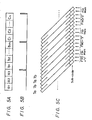
- the first embodiment includes a digital audio tape recorder (DAT) 1 with a rotary head drum 11 around the peripheral surface of which a magnetic tape 12 is wrapped over an angular range of about 90° of head travel.
- the tape 12 is transported past the head drum 11 by a tape transport mechanism 19.
- Two rotary heads A and B are mounted in the rotary head drum 11, and two oblique tracks are recorded and/or reproduced by the heads A and B once per revolution of the head drum 11 as shown more clearly in Figure 2.
- Incoming digital data si supplied to an input and output (I/O) circuit 13 of the DAT 1 and thence to a digital signal processor 14, in which it is converted into the DAT format.
- the digital signal converted in accordance with the DAT format is supplied through a recording amplifier 15 and a recording side contact R of a recording/reproducing change-over switch 16 to the heads A and B, and is thereby recorded on the tape .
- the reproduced signal is supplied through a reproducing side contact P of the recording/reproducing switch 16 and a playback amplifier 17 to the signal processor 14, in which the reproduced signal is reconverted into the digital data and is then supplied through the I/O circuit 13.
- An incoming signal is also supplied to a system control circuit 18, the head drum 11 is controlled to rotate, the tape transport mechanism 19 transports the tape 12, and the recording/reproducing switch 16 changes in position. Also, upon recording, the signal from the system control circuit 18 is supplied to the signal processor 14 which then produces a sub-code signal or the like which will be described later. Upon reproduction, the signal extracted by the signal processor 14 is supplied to the system control circuit 18 for tracking control operation, and this signal is fed out.
- DAT 1 by connecting a digital-to-analoque/analogue-to-digital DA/AD converting circuit to the output of the I/O circuit 13, and a predetermined control apparatus to the output of the system control circuit 18, it is possible to record and/or reproduce, for example, an analogue audio signal.
- an interface bus 3 is connected through a controller 2 as an external apparatus to the DAT 1.
- the interface bus 3 may be of the type which conforms, for example, to the small computer system interface (SCSI) standard (see 'NIKKEI ELECTRONICS', pages 102 to 107, published by Nihon Keizai Shinbunsha on 6 October 1986).
- SCSI small computer system interface
- a host computer 5 and a hard disc drive (HDD) 6 are connected to the interface but 3 through a host adaptor 4.
- a protocol control circuit 21 is connected to the bus 3.
- the data and the control signal are interchanged between a microcomputer 22 which controls the operation of the controller 2, a memory control or dynamic memory access (DMA) circuit 23 and the bus 3.
- the microcomputer 22 not only controls the operation of the controller 2 but also detects the address of the DMA circuit 23 and controls the operation of the DMA circuit 23.
- data is interchanged between a buffer memory 24 and the bus 3 through the DMA circuit 23. Further, data is interchanged between the buffer memory 24 and the signal processor 14 via I/O circuits 25 and 13.
- the control signal is interchanged between the microcomputer 22 and the system control circuit 18.
- data written in the HDD 6 is supplied through the bus 3 to the controller 2 in response to the transfer request from the controller 2 during recording, and is then written in the buffer memory 24 through the DMA circuit 23.
- the data written in the buffer memory 24 is read out through the I/O circuit 25 and then fed to the DAT 1.
- the data supplied to the I/O circuit 13 is regarded as being equivalent to that derived from the analogue-to-digital converting circuit when an audio signal is recorded.
- this data is converted circuit in accordance with a predetermined DAT format by the signal processor 14 and is thereby recorded on the tape 12 by the heads A and B.
- the signal reproduced from the tape 12 by the heads A and B is reconverted by the signal processor 14 and thereby data corresponding to the audio signal is produced.
- This data is supplied through the I/O circuit 13 to the controller 2.
- the data written in the buffer memory 24 through the I/O circuit 25 is read out through the DMA circuit 23 and then written in the HDD 6 through the bus 3.
- two tracks Ta and Tb respectively recorded by the heads A and B constitute one frame, and each of these tracks Ta and Tb is formed as though recorded from the bottom of the drawing.
- the signal is recorded on each of the tracks Ta and Tb over an angular range of 90°.
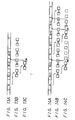
- Each of the tracks Ta and Tb is formed (viewed from right to left in Figure 2) of a predetermined margin area of 5.051°, a phase locked loop (PLL) preamble sub-code area of 0.918°, a first sub-code area of 3.673°, a postamble area of 0.459°, an interblock gap area of 1.378°, a tracking (auto tracking finding (ATF)) signal area of 2.296°, an interblock gap area of 1.378°, a PLL preamble sub-code area of 0.918°, a data area of 58.776°, an interblock gap area of 1.378°, an ATF signal area of 2.296°, an interblock gap area of 1.378°, a PLL preamble sub-code area of 0.918°, a second sub-code area of 3.673°, a postamble area of 0.459° and a margin area of 5.051° in this sequential order, although the scale of Figure 2 is not accurate.
- PLL phase
- the data from the I/O circuit 13 is supplied to the signal processor 14, in which it is added to the error-detection and error-correction codes and others in accordance with the predetermined DAT format, interleaved in a predetermined relationship, distributed and then inserted into the respective data areas of the tracks Ta and Tb.
- 5760 bytes of original data can be recorded in the two data areas which constitute a single frame.
- this apparatus is used as a data streamer, however, incoming data is processed in units of 2 n , for example 512 bytes. Since the recording capacity of 5760 bytes forming one frame is not an integral multiple of this, it is not possible to establish matching between the DAT 1 and the external apparatus.
- the DAT 1 can be utilized as a data streamer.
- the head drum 11 is rotated at for example, 2000 rpm, data can be recorded at extremely high speed, for example 192,000 bytes per second. Also, the amount of recording medium used can be very much reduced. Also, since matching between the DAT 1 and the external apparatus is established, it is possible to record and/or reproduce data satisfactorily.
- An error-correction code of the data to be recorded or the like may be recorded in the remaining 128 bytes instead of recording filler data. If the error-correction code shares much of the remaining 128 bytes, the number of blocks of data to be recorded in one frame may be decreased and the code area or the like may be increased.
- 2048 bits of data can be recorded in the first and second sub-code area shown in Figure 2, respectively.
- the 2048 bits of data in the sub-code area are divided into pack data, each pack data being formed of 64 bits, and a time code for the recorded signal and information such as a calendar (recording date ) or the like can be recorded for every pack.
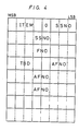
- FIG. 4 schematically illustrates the pack format therefor.
- 64 bits are each divided into eight words and each word is formed of eight bits.
- MSB most significant bit
- ITEM area is assigned to an ITEM area and this ITEM area is made common to the recording format of the audio signal.
- the contents of this pack format are expressed by a four bit binary code.
- nine binary codes are already defined so as to record the audio singal, and the arbitrary binary codes in the remaining seven binary codes are defined for the data recorder.
- LSB least significant bit
- SSNO save set number
- FNO file number
- Eight bits of the seventh word are assigned to a situation area in which data indicating the situation of the frame are provided. That is, in the eight bits of the seventh word, the starting bit at the MSB end is assigned to a lead-out flag area indicating that the frame is the final position of the back-up data (lead-out); the second bit is assigned to a data invalid flag area indicating that the data of the frame is invalid; the third bit is assigned to an amble flag area indicating the amble frame of the starting or ending point of the recorded data; and the forth bit thereof is assigned to a file mark flag area indicating the file mark frame.
- bits at the LSB end of the seventh word express in binary code the number of blocks recorded per frame where one block represents the amount of data recorded per frame, for example, the unit amount of incoming and outgoing data of the external apparatus.
- the fifth bit from the MSB end of the first word in made 'O', and four bits at the MSB end of the fourth word are assigned to extension bits (TBD) and are all made 'O' for the time being.
- eight bits of the eighth word are assigned to parity data for the first to seventh words.
- the write address and the read address of the DMA circuit 23 are compared with each other.
- a signal indicative of that state is supplied to the microcomputer 22.
- the signal from the microcomputer 22 is supplied through the system control circuit 18 to the signal processor 14, whereby the data invalid flag is set to '1' in the second bit of the seventh word in the sub-code portion of the pack format of the data recorder. Also, arbitrary, invalid data is recorded in the data area.
- the recording Since the recording is continuous even when the supply of data is interrupted, it is possible to avoid the problem that the recording is stopped and then resumed with a delay of time caused by the interruption. Thus, the recording can always be carried out smoothly.
- DAT 1 starts recording the data under the condition that the FNO provided in the third word of the sub-code area of the pack format for the data recorder is first selected to be 'O'. Also, if under this condition a file mark signal is supplied from the computer 5, the corresponding write address from the DMA circuit 23 is written in the microcomputer 22. Then, if the read address of the DMA circuit 23 is detected and this read address coincides with the thus written address, then predetermined invalid data is read out from the buffer memory 24 and the invalid data is inserted into the remainder of the data portion of one frame in accordance with the recording format of the DAT 1.
- Invalid data is also read out during the succeeding frame period and the FNO of the pack format for the data recorder is incremented by '1'. Also, the file mark flag is set to '1' in the fourth bit of the seventh word. Then, the next data is recorded from the frame next to the succeeding frame and the FNO at that time is made the same as that of the immediately-preceding file mark.
- the FNO is selected to be the same value.
- the file mark signal is recorded as follows.
- the FNO of the frame reproduced at the time when the search is requested is detected and than added to the number ( ⁇ ) of the file marks that should be searched for.
- the added value and the above-mentioned detected value are compared with each other. If the added value is larger than the detected value, the search is started at high speed in the forward direction, while if it is smaller, the search is started at high speed in the reverse direction.
- the FNO detected and the aforesaid added value are compared with each other. If the relationship between the added value and the detected value is changed, the search direction for the recorded signal is reversed and the search speed is reduced by half, thus making it possible to search for a desired file mark.
- bit number of the FNO must be secured so as to prevent the same FNO from becoming continuous in the frames detected during the highest speed search mode.
- predetermined amble signals are located at the starting and ending portions of the recorded data. Also, there is provided a lead-out signal having a duration sufficient for it to be read in the high speed search mode at the end of the recording.
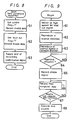
- Figure 6 illustrates a flow chart to which references will be made in explaining the aforesaid operation.
- the recording is started, it is determined at a first step 31 whether the recording is started from the beginning of the tape 12 or not. If it is determined that the recording is started from the beginning of the tape 12 as represented by YES, the program goes to step 32 in which the amble flag is set to '1' at the third bit of the seventh word of the subcode area of the pack format for the data recorder and a frame in which arbitrary, invalid data is inserted into the data portion is recorded for a predetermined period. At that time, the respective values provided in the first to sixth words of the pack format for the same data recorder are reset to the initial values or particular values. Particularly, the AFNO does not increment from 'O' but repeats the same value.
- the recording of the amble signal is ended, the data is recorded at step 33 and this recording is continued until it is decided at the next decisional step 34 that the recording is ended or that the apparatus is disabled for recording (placed in the under-run condition) because the buffer memory 24 does not have sufficient data. If this stop condition is detected as represented by YES at step 34, a similar amble frame is recorded during a predetermined period at step 35. Then, it is determined at the next decisional step 36 whether the stop condition is the under-run condition or not.
- step 37 in which the lead-out flag is set at '1' in the first bit of the seventh word and the frame in which the invalid data is inserted into the data portion is recorded for a time period of sufficient duration so that it can be detected in the high speed search mode, for example, for more than 300 frames, if the high speed search mode, for example, for more than 300 frames, if the high speed search operation is carried out at a speed 300 times as high as the recording speed.
- the values of the first to sixth words are selected to be equal to those in the period of the preceding data signal. Thereafter, the tape 12 is stopped at the next step 38 and the recording is ended.
- amble frame is provided at the starting and ending portions of the recorded data and the lead-out frame of predetermined time duration is recorded next to the last amble frame.
- step 31 it is determined at decisional step 31 whether or not the recording is started from an intermediate point on the tape 12. If so, the processing goes to step 39 in which he lead-out signal is searched for at high speed. If the frame in which the lead-out flag is set as mentioned above is recorded continuously for more than 300 frames and is reproduced at a tape speed 300 times as high as that of the recording mode, the heads A and B reproduce the sub-code areas of the corresponding tracks more than once, whereby the lead-out signal can be searched for by detecting the lead-out flag.
- the program goes to the next step 40.
- step 40 reproduction in the reverse direction is carried out towards the preceding amble signal and the amble period is reproduced, for example, for about one to two seconds at step 41.
- step 42 the tape 12 is transported in the normal mode. Then, it is determined at decisional step 43 whether the apparatus is actuated nor not. If the apparatus is actuated as represented by YES at step 43, the amble signal is taken in at step 44. Then, the amble signal to be recorded for several frames at step 45.
- the amble signal to be recorded herein is as follows: '1' is set for the amble flag at the third bit of the seventh word of the aforesaid pack format for the data recorder; arbitrary, invalid data is inserted into the data portion; the value of the preceding amble signal detected when the SSNO of the first and second words of the pack format for the data recorder are reproduced in the reverse direction is incremented by '1'; the FNO of the third word is changed to 'O'; and the absolute frame numbers of the fourth to sixth words repeat the same preceding values.
- step 46 reverse reproduction is carried out. This reverse reproduction is continued until the reproduced signal is changed from the amble signal to the data signal at the next decisional step 48 whether the under-run condition is released or not. If the under-run condition is released, the program goes to step 42. Thereafter, a similar routine for recording the signal at the starting portion (from steps 42 to 45 and step 33) is executed.
- the amble signal is recorded at the starting and ending portions of the recording signal, it is possible to actuate the heads A and B during this period. Thus, the starting portion of the data can be prevented from being cut off. Also, since the previously-recorded signal can be erased by the over-write, there is then no risk that misoperation will be caused by the remaining signal portions that are not fully erased. Therefore, the recording can be made satisfactorily by using the append command.
- Figure 8 is a flow chart to which reference will be made in explaining how to record the lead-out signal.
- this routine is started.
- an amble flag is set to '1' in the third bit of the seventh word of the sub-code area of the pack format for the data recorder.
- the frame in which arbitrary, invalid data is inserted into the data portion thereof is recorded for a period of about two to three seconds.
- the respective values provided in the first to sixth words of the same pack format for the data recorder are made the same as those of the period of the preceding data signal.
- the AFNO is prevented from being incremented from the previous value but repeats the same value.
- the lead-out flag is set to '1' in the first bit of the seventh word similarly and the frame in which invalid data is inserted into the data portion thereof is recorded for a period which can be detected by the high speed search operation, for example more than 300 frames can be recorded if the high speed search is carried out at a speed 200 times as high as the normal speed. Also in this case, the values of the first to sixth words are made the same as those described hereinbefore.
- a confirmation signal indicative of the end of the recording is supplied to the host computer 5 and this routine is ended.
- step 61 the above-mentioned lead-out signal is searched for at high speed.
- the heads A and B reproduce the sub code areas of the corresponding tracks more than once during this time period.
- the lead-out signal can be searched for by detecting the lead-out flag.
- the program goes to the next step 62, in which reverse reproduction is carried out towards the preceding amble signal and the amble signal is reproduced during the amble period of about one to two seconds.
- the tape 12 is transported in the normal or forward direction. If the apparatus is actuated, the program goes to step 65 in which the amble signal is recorded for a period of several frames. The ample signal thus recorded is such that '1' is set in the amble flag at the third bit of the seventh word of the pack format for the data recorder.
- Arbitrary, invalid data is inserted into the data portion;
- the SSNO of the first and second words in the pack format for the data recorder is such that '1' is added to the previous amble signal detected by the reverse reproduction;
- the FNO of the third word is made 'O' and the AFNO of the fourth to sixth words repeat the same value as those before.
- the program goes to the next step 66, in which data from the computer 5 is recorded. This recording is continued until the end command from the computer 5 is supplied at step 67.
- an end routine 68 similar to that shown in Figure 8 is executed and then, the routine is ended.
- FIG. 10 illustrates another embodiment of data streamer DAT according to the present invention.
- two recording and/or reproducing rotary heads A and B are mounted on the rotary head drum 11 with an angular spacing of 180° therebetween. Two oblique tracks are recorded and/or reproduced per one revolution of the rotary head drum 11.
- Incoming digital data is supplied to the I/O circuit 13.
- the signal from the I/O circuit 13 is supplied to the digital signal processor 14, in which it is converted into a signal in accordance with the above-mentioned DAT format.
- the DAT format converted signal is supplied through the recording amplifier 15 and the recording side contact R of the recording/reproducing change-over switch 16 to the heads A and B and is thereby recorded on tape 12.
- the reproduced signal is supplied through the reproducing side contact P of the recording/reproducing switch 16 to one fixed contact a of a change-over switch 35.
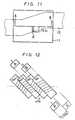
- the head drum 11 On the head drum 11, there are also mounted detecting and reproducing rotary heads A ⁇ and B ⁇ at positions delayed from the recording and reproducing heads A and B by 270° each relative to the direction in which the head drum 11 is rotated as shown by an arrow. Also, the heads A ⁇ and B ⁇ are mounted on the head drum 11 so as to have a difference in level of, for example, 1.75 track pitches (Tp) as illustrated in Figure 11.
- Tp 1.75 track pitches
- the heads A and B each have a width 1.5 times as wide as the track pitch Tp as shown in Figure 12.
- an amount equal to 0.5 track pitch of the track recorded by, for example, the head A can be erased by recording the next track by the head B having no difference in level and disposed at a position delayed from the former head by 180°, so that guardbandless recording can be carried out.
- the head A ⁇ is mounted without a difference in level, the relative position of the head A ⁇ is as shown by a broken line in Figure 12. But since the head A ⁇ is disposed with difference in level of 1.75 track pitches, the head A ⁇ is located at a track position where the portion recorded by the head A passes through the position of the head B. If the heads A and B have different head gap azimuth angles, the azimuth angles of the heads A nad A ⁇ , and those of the heads B and B ⁇ are made equal to each other.
- the reproduced signal from the heads A ⁇ and B ⁇ is supplied to the other fixed contact b of the change-over switch 35, and the signal produced at the movable contact c of the change-over switch 35 is supplied through the playback amplifier 17 to the signal processor 14, in which it is reconverted into digital data.
- the digital data from the signal processor 14 is supplied through the I/O circuit 13.
- the signal processor 14 includes a circuit for generating error-detecting and error-correcting codes an error-detecting circuit and an error-correcting circuit using the above-mentioned codes.
- a common computer circuit is employed for generating the error-correcting code and for correcting errors using the error-correcting code. Accordingly, upon recording, the error-correcting circuit is disabled when the error-detecting code and the errorcorrecting code generating circuit is operated.
- the error-detecting circuit can be used independently.
- the signal reproduced by the heads A ⁇ and B ⁇ is supplied through the change-over switch 35 and the playback amplifier 17 to the signal processor 14, for the detection of errors, as described above.
- the error-detected signal is supplied to the system control circuit 18, under control of which the same data is re-recorded.
- the signal from the system control circuit 18 is supplied to the microcomputer 22. Then, the DMA circuit 23 is controlled to allow the buffer memory 24 to read out again the immediately preceding three frames of data.
- the DMA circuit 23 is controlled to allow the buffer memory 24 to read out again the immediately preceding three frames of data.
- the DAT 1 When the DAT 1 is used as a data streamer for a computer, it is necessary to record the file mark and the end signal indicative of the section of data derived from the computer. In that case, in order for the file mark to be searched with ease, it has been proposed that the end signal and the file mark be recorded for one frame. However, in such a case, if data FM forming, for example, the file mark frame is directly recorded just after the last data X which forms the above-mentioned frame, when an error is detected from the data X or previous data, the data FM of file mark frame is repeatedly recorded.
- an arbitrary signal period of two frames is provided between the last data X and the file mark frame FM as shown in Figure 15A.
- This arbitrary signal period may be formed by repeatedly recording the invalid data or the last data X under the control of the microcomputer 22 in the controller 2.
- the signal reproduced from the tape 12 by the heads A and B is supplied to the signal processor 14, in which it is reconverted into data corresponding to an audio signal. If an error is detected from the reproduced data, the tape 12 is not immediately rewound and reproduced again, because there is a possibility that the same data is recorded repeatedly as described above. However, if data N+3 is reproduced before correct data is reproduced as data N, or data such as the file mark or the like is reproduced before correct data is reproduced as data X and X-1, the tape 12 is immediately rewound and reproduced again. In this case, there remains a possibility that correct data can be obtained from the frame in which data with a detected error is recorded.
- this data is supplied through the I/O circuit 13 to the controller 2.
- data written in the buffer memory 24 through the I/O circuit 25 is read through the DMA circuit 23 and then written in the HDD 6 via the bus 3.
- the original recorded signal is reproduced by the head A ⁇ from the track recorded by, for example the head A and one portion of which is erased by the recording by the head B and then checked, the recorded signal can always be checked accurately without being affected by the disturbed movement of the tape 12.
- the recorded signal can always be checked accurately without being affected by the disturbed movement of the tape 12.
- the reproducing and detecting heads A ⁇ and B ⁇ are not necessary formed with high accuracy. On the contrary, even if the accuracy is made low, it is still possible to check the data under more strict conditions. Further, the difference in level between the heads A ⁇ and B ⁇ is not limited to the above example of 1.75 Tp, but may be changed freely in order to afford more strict conditions. Furthermore, the difference in level between the heads A ⁇ and B ⁇ may be changed with the angular distance between the heads A and A ⁇ , and B and B ⁇ .
Priority Applications (1)
| Application Number | Priority Date | Filing Date | Title |
|---|---|---|---|
| AT87311151T ATE86046T1 (de) | 1986-12-19 | 1987-12-17 | Datenaufzeichnung. |
Applications Claiming Priority (14)
| Application Number | Priority Date | Filing Date | Title |
|---|---|---|---|
| JP303080/86 | 1986-12-19 | ||
| JP61303080A JPS63155470A (ja) | 1986-12-19 | 1986-12-19 | デ−タレコ−ダ |
| JP30588186A JPH0828056B2 (ja) | 1986-12-22 | 1986-12-22 | デ−タレコ−ダ |
| JP305881/86 | 1986-12-22 | ||
| JP61313856A JPH0727687B2 (ja) | 1986-12-24 | 1986-12-24 | デ−タレコ−ダ |
| JP31385786A JPH0766653B2 (ja) | 1986-12-24 | 1986-12-24 | デ−タレコ−ダ |
| JP313857/86 | 1986-12-24 | ||
| JP313856/86 | 1986-12-24 | ||
| JP61314922A JP2522272B2 (ja) | 1986-12-25 | 1986-12-25 | デ−タレコ−ダ |
| JP314922/86 | 1986-12-25 | ||
| JP2084/87 | 1987-01-08 | ||
| JP62002084A JPS63171404A (ja) | 1987-01-08 | 1987-01-08 | デ−タレコ−ダ |
| JP62004434A JPH0833976B2 (ja) | 1987-01-12 | 1987-01-12 | 記録再生装置 |
| JP4434/87 | 1987-01-12 |
Publications (3)
| Publication Number | Publication Date |
|---|---|
| EP0272130A2 true EP0272130A2 (fr) | 1988-06-22 |
| EP0272130A3 EP0272130A3 (en) | 1990-04-04 |
| EP0272130B1 EP0272130B1 (fr) | 1993-02-24 |
Family
ID=27563169
Family Applications (1)
| Application Number | Title | Priority Date | Filing Date |
|---|---|---|---|
| EP87311151A Expired - Lifetime EP0272130B1 (fr) | 1986-12-19 | 1987-12-17 | Enregistrement de données |
Country Status (6)
| Country | Link |
|---|---|
| US (1) | US4873589A (fr) |
| EP (1) | EP0272130B1 (fr) |
| KR (1) | KR960001486B1 (fr) |
| AU (1) | AU604807B2 (fr) |
| CA (1) | CA1292565C (fr) |
| DE (1) | DE3784323T2 (fr) |
Cited By (17)
| Publication number | Priority date | Publication date | Assignee | Title |
|---|---|---|---|---|
| EP0286412A2 (fr) * | 1987-04-07 | 1988-10-12 | Sony Corporation | Appareil pour enregistrer et/ou reproduire des données numériques |
| EP0297809A2 (fr) * | 1987-06-29 | 1989-01-04 | Sony Corporation | Procédés et appareils pour l'enregistrement et/ou la reproduction de données numériques |
| EP0321077A2 (fr) * | 1987-12-14 | 1989-06-21 | Sony Corporation | Appareil et méthode pour enregistrer un signal numérique |
| EP0323890A2 (fr) * | 1988-01-08 | 1989-07-12 | Hewlett-Packard Limited | Méthode de stockage de données |
| EP0327188A2 (fr) * | 1988-01-08 | 1989-08-09 | Hewlett-Packard Limited | Méthode de stockage de données sur bande d'enregistrement |
| EP0327201A2 (fr) * | 1988-01-08 | 1989-08-09 | Hewlett-Packard Limited | Enregistreurs de données et méthodes pour enregistrer des données numériques |
| EP0379222A1 (fr) * | 1989-01-19 | 1990-07-25 | Sharp Kabushiki Kaisha | Appareil pour enregistrer et/ou reproduire des données |
| EP0429727A1 (fr) * | 1989-11-30 | 1991-06-05 | Sony Corporation | Enregistreur de données |
| EP0437219A1 (fr) * | 1990-01-06 | 1991-07-17 | Victor Company Of Japan, Limited | Appareil de reproduction avec balayage hélicoidal pour données numériques |
| EP0505127A2 (fr) * | 1991-03-17 | 1992-09-23 | Sony Corporation | Méthodes et appareil d'enregistrement de données |
| EP0509637A2 (fr) * | 1991-03-15 | 1992-10-21 | Fujitsu Limited | Dispositif de mémoire à bande magnétique |
| EP0509642A2 (fr) * | 1991-03-17 | 1992-10-21 | Sony Corporation | Dispositif pour l'enregistrement et/ou la reproduction de données |
| EP0540352A2 (fr) * | 1991-10-31 | 1993-05-05 | Sony Corporation | Dispositif d'enregistrement et de reproduction de données |
| WO1993017430A1 (fr) * | 1992-02-28 | 1993-09-02 | Ampex Systems Corporation | Systeme d'enregistrement de donnees a capacite logique de surenregistrement |
| WO1993017419A1 (fr) * | 1992-02-28 | 1993-09-02 | Ampex Systems Corporation | Systeme d'enregistrement de donnees comprenant des indicateurs de format de fin d'enregistrement et de debut d'enregistrement |
| US5499147A (en) * | 1993-12-02 | 1996-03-12 | Industrial Technology Research Institute | Rotary head recording and reproduction apparatus with memory and method of operation which compares a reproduced signal with an original signal |
| EP0794531A2 (fr) * | 1996-03-04 | 1997-09-10 | Hitachi, Ltd. | Appareil d'enregistrement/reproduction de signaux digitaux et méthode d'enregistrement |
Families Citing this family (35)
| Publication number | Priority date | Publication date | Assignee | Title |
|---|---|---|---|---|
| US5144500A (en) * | 1988-01-08 | 1992-09-01 | Sony Corporation | Method and apparatus for reproducing multiply recorded data |
| US5144501A (en) * | 1988-01-08 | 1992-09-01 | Sony Corporation | Data recorder and method of operation |
| US5115240A (en) * | 1989-09-26 | 1992-05-19 | Sony Corporation | Method and apparatus for encoding voice signals divided into a plurality of frequency bands |
| US5047873A (en) * | 1989-12-04 | 1991-09-10 | Honeywell Inc. | Split swipe tape recording |
| JPH0782708B2 (ja) * | 1990-01-26 | 1995-09-06 | ティアツク株式会社 | データの追加書込み方法 |
| JPH0490181A (ja) * | 1990-07-31 | 1992-03-24 | Sony Corp | 記録再生装置 |
| EP0505983B1 (fr) * | 1991-03-29 | 1997-06-18 | Sony Corporation | Tête magnétique et une tête d'enregistrement magnétique digital |
| US5287233A (en) * | 1991-08-06 | 1994-02-15 | R-Byte Inc. | Digital data storage magnetic tape system comprising a single chip processor to control a tape tension servo, and a head drum servo |
| US5359468A (en) * | 1991-08-06 | 1994-10-25 | R-Byte, Inc. | Digital data storage tape formatter |
| US5309300A (en) * | 1991-08-06 | 1994-05-03 | R-Byte, Inc. | Beginning/end of tape detection system |
| US5398140A (en) * | 1991-08-06 | 1995-03-14 | R-Byte, Inc. | Digital data tape storage automatic track follower system |
| JP3198550B2 (ja) * | 1991-09-03 | 2001-08-13 | ソニー株式会社 | 圧縮データ記録方法及び圧縮データ記録再生装置 |
| JP3153933B2 (ja) * | 1992-06-16 | 2001-04-09 | ソニー株式会社 | データ符号化装置及び方法並びにデータ復号化装置及び方法 |
| JPH06203486A (ja) * | 1992-12-31 | 1994-07-22 | Sony Corp | 記録再生制御装置 |
| JP3186292B2 (ja) * | 1993-02-02 | 2001-07-11 | ソニー株式会社 | 高能率符号化方法及び装置 |
| US5706260A (en) * | 1993-03-09 | 1998-01-06 | Sony Corporation | Apparatus for and method of synchronously recording signals onto a disk medium by a single head |
| JP3186307B2 (ja) * | 1993-03-09 | 2001-07-11 | ソニー株式会社 | 圧縮データ記録装置及び方法 |
| US5581654A (en) * | 1993-05-25 | 1996-12-03 | Sony Corporation | Method and apparatus for information encoding and decoding |
| US5448420A (en) * | 1993-08-02 | 1995-09-05 | Dictaphone Corporation | Method and a system for storing audio |
| US5608713A (en) * | 1994-02-09 | 1997-03-04 | Sony Corporation | Bit allocation of digital audio signal blocks by non-linear processing |
| JP3186412B2 (ja) * | 1994-04-01 | 2001-07-11 | ソニー株式会社 | 情報符号化方法、情報復号化方法、及び情報伝送方法 |
| JP3277699B2 (ja) * | 1994-06-13 | 2002-04-22 | ソニー株式会社 | 信号符号化方法及び装置並びに信号復号化方法及び装置 |
| JP3277705B2 (ja) | 1994-07-27 | 2002-04-22 | ソニー株式会社 | 情報符号化装置及び方法、並びに情報復号化装置及び方法 |
| JP3341474B2 (ja) * | 1994-07-28 | 2002-11-05 | ソニー株式会社 | 情報符号化方法及び復号化方法、情報符号化装置及び復号化装置、並びに情報記録媒体 |
| JP3557674B2 (ja) * | 1994-12-15 | 2004-08-25 | ソニー株式会社 | 高能率符号化方法及び装置 |
| JPH09282807A (ja) * | 1996-04-13 | 1997-10-31 | Sony Corp | テープ状記録媒体の記録再生装置及び記録再生方法 |
| US6775372B1 (en) | 1999-06-02 | 2004-08-10 | Dictaphone Corporation | System and method for multi-stage data logging |
| US6249570B1 (en) | 1999-06-08 | 2001-06-19 | David A. Glowny | System and method for recording and storing telephone call information |
| US6252946B1 (en) | 1999-06-08 | 2001-06-26 | David A. Glowny | System and method for integrating call record information |
| US6246752B1 (en) | 1999-06-08 | 2001-06-12 | Valerie Bscheider | System and method for data recording |
| US6252947B1 (en) * | 1999-06-08 | 2001-06-26 | David A. Diamond | System and method for data recording and playback |
| US6869644B2 (en) * | 2000-10-24 | 2005-03-22 | Ppg Industries Ohio, Inc. | Method of making coated articles and coated articles made thereby |
| US20140181396A1 (en) * | 2012-12-20 | 2014-06-26 | Amazon Technologies, Inc. | Virtual tape using a logical data container |
| US10013166B2 (en) | 2012-12-20 | 2018-07-03 | Amazon Technologies, Inc. | Virtual tape library system |
| JP2022158641A (ja) * | 2021-04-02 | 2022-10-17 | 富士通株式会社 | 情報処理装置及び情報処理方法 |
Citations (4)
| Publication number | Priority date | Publication date | Assignee | Title |
|---|---|---|---|---|
| US3439344A (en) * | 1966-08-09 | 1969-04-15 | Sperry Rand Corp | Continuous data recording apparatus |
| US4358799A (en) * | 1979-01-17 | 1982-11-09 | U.S. Philips Corporation | Apparatus for recording and/or reproducing signals |
| EP0084950A2 (fr) * | 1982-01-19 | 1983-08-03 | University College London | Système de stockage de données utilisant une bande vidéo |
| EP0203797A2 (fr) * | 1985-05-29 | 1986-12-03 | Sony Corporation | Appareil pour enregistrer et/ou reproduire un signal numérique |
Family Cites Families (6)
| Publication number | Priority date | Publication date | Assignee | Title |
|---|---|---|---|---|
| BE633599A (fr) * | 1962-06-20 | |||
| JPS5815843B2 (ja) * | 1979-11-16 | 1983-03-28 | 株式会社東芝 | 再生信号処理方式 |
| US4494155A (en) * | 1982-11-08 | 1985-01-15 | Eastman Kodak Company | Adaptive redundance in data recording |
| KR890003037B1 (ko) * | 1983-06-10 | 1989-08-19 | 가부시기 가이샤 히다찌세이사꾸쇼 | 회전헤드형 자기기록 재생장치 |
| SE8403625D0 (sv) * | 1984-07-09 | 1984-07-09 | Mydata Automation Ab | Kassettmagasin for ytmonteringsmaskin |
| JPS61150180A (ja) * | 1984-12-24 | 1986-07-08 | Sony Corp | 記録再生装置 |
-
1987
- 1987-12-14 AU AU82517/87A patent/AU604807B2/en not_active Ceased
- 1987-12-15 US US07/133,010 patent/US4873589A/en not_active Expired - Lifetime
- 1987-12-17 EP EP87311151A patent/EP0272130B1/fr not_active Expired - Lifetime
- 1987-12-17 DE DE8787311151T patent/DE3784323T2/de not_active Expired - Fee Related
- 1987-12-18 CA CA000554745A patent/CA1292565C/fr not_active Expired - Lifetime
- 1987-12-19 KR KR1019870014531A patent/KR960001486B1/ko not_active IP Right Cessation
Patent Citations (4)
| Publication number | Priority date | Publication date | Assignee | Title |
|---|---|---|---|---|
| US3439344A (en) * | 1966-08-09 | 1969-04-15 | Sperry Rand Corp | Continuous data recording apparatus |
| US4358799A (en) * | 1979-01-17 | 1982-11-09 | U.S. Philips Corporation | Apparatus for recording and/or reproducing signals |
| EP0084950A2 (fr) * | 1982-01-19 | 1983-08-03 | University College London | Système de stockage de données utilisant une bande vidéo |
| EP0203797A2 (fr) * | 1985-05-29 | 1986-12-03 | Sony Corporation | Appareil pour enregistrer et/ou reproduire un signal numérique |
Non-Patent Citations (5)
| Title |
|---|
| MINI-MICRO SYSTEMS, vol. 15, no. 10, October 1982, pages 257-264, Boston, Massachusetts, US; J. TILESTON: "Streaming-tape parameters determine formatter characteristics" * |
| MINI-MICRO SYSTEMS, vol. 16, no. 4, April 1983, pages 179-182, Denver, Colorado, US; J. PROPER: "Video cassette recorders for disk backup" * |
| MINI-MICRO SYSTEMS, vol. 16, no. 6, May 1983, pages 261-264, Denver, Colorado, US; K. KELLY: "Streaming-tape drives emulate start/stop machines" * |
| NAVY TECHNICAL DISCOLOSURE BULLETIN, vol. 11, no. 2, December 1985, Arlington, Virginia, US; R.L. NELSON et al.: "Videotape digital data collection/recovery system" * |
| SMPTE JOURNAL, vol. 95, no. 8, August 1986, pages 805-810, White Plains, New York, US; H.R. LEINER: "Digital medical image storage on VHS cassette" * |
Cited By (39)
| Publication number | Priority date | Publication date | Assignee | Title |
|---|---|---|---|---|
| EP0286412A2 (fr) * | 1987-04-07 | 1988-10-12 | Sony Corporation | Appareil pour enregistrer et/ou reproduire des données numériques |
| EP0286412A3 (en) * | 1987-04-07 | 1990-01-31 | Sony Corporation | Apparatus for recording and/or reproducing digital data |
| US5012459A (en) * | 1987-06-29 | 1991-04-30 | Sony Corporation | Data recorder |
| EP0297809A2 (fr) * | 1987-06-29 | 1989-01-04 | Sony Corporation | Procédés et appareils pour l'enregistrement et/ou la reproduction de données numériques |
| EP0297809A3 (en) * | 1987-06-29 | 1989-12-13 | Sony Corporation | Methods of and apparatuses for recording and/or reproducing digital data |
| EP0321077A2 (fr) * | 1987-12-14 | 1989-06-21 | Sony Corporation | Appareil et méthode pour enregistrer un signal numérique |
| US5134529A (en) * | 1987-12-14 | 1992-07-28 | Sony Corporation | Apparatus and method for recording a digital signal |
| EP0321077A3 (fr) * | 1987-12-14 | 1991-05-29 | Sony Corporation | Appareil et méthode pour enregistrer un signal numérique |
| EP0327188A3 (fr) * | 1988-01-08 | 1990-02-07 | Hewlett-Packard Limited | Méthode de stockage de données sur bande d'enregistrement |
| EP0323890B1 (fr) * | 1988-01-08 | 1993-09-22 | Hewlett-Packard Limited | Méthode de stockage de données |
| EP0327201A2 (fr) * | 1988-01-08 | 1989-08-09 | Hewlett-Packard Limited | Enregistreurs de données et méthodes pour enregistrer des données numériques |
| EP0327188A2 (fr) * | 1988-01-08 | 1989-08-09 | Hewlett-Packard Limited | Méthode de stockage de données sur bande d'enregistrement |
| EP0327201B1 (fr) * | 1988-01-08 | 1993-12-29 | Hewlett-Packard Limited | Enregistreurs de données et méthodes pour enregistrer des données numériques |
| EP0323890A2 (fr) * | 1988-01-08 | 1989-07-12 | Hewlett-Packard Limited | Méthode de stockage de données |
| EP0379222A1 (fr) * | 1989-01-19 | 1990-07-25 | Sharp Kabushiki Kaisha | Appareil pour enregistrer et/ou reproduire des données |
| US5124986A (en) * | 1989-01-19 | 1992-06-23 | Sharp Kabushiki Kaisha | Data recording/reproducing apparatus |
| US5379152A (en) * | 1989-11-28 | 1995-01-03 | Sony Corporation | Data recorder which partitions the recording medium into data information and table of contents information |
| EP0429727A1 (fr) * | 1989-11-30 | 1991-06-05 | Sony Corporation | Enregistreur de données |
| US5274513A (en) * | 1990-01-06 | 1993-12-28 | Victor Company Of Japan, Ltd. | Search system for helical scan digital data reproduction apparatus |
| EP0437219A1 (fr) * | 1990-01-06 | 1991-07-17 | Victor Company Of Japan, Limited | Appareil de reproduction avec balayage hélicoidal pour données numériques |
| US5525902A (en) * | 1991-03-15 | 1996-06-11 | Fujitsu Limited | Magnetic tape storage apparatus writing status information to magnetic tape indicating a tape abnormality |
| US5384673A (en) * | 1991-03-15 | 1995-01-24 | Fujitsu Limited | Magnetic-tape storage apparatus |
| EP0509637A2 (fr) * | 1991-03-15 | 1992-10-21 | Fujitsu Limited | Dispositif de mémoire à bande magnétique |
| EP0509637A3 (en) * | 1991-03-15 | 1993-06-02 | Fujitsu Limited | Magnetic tape storage apparatus |
| EP0505127A2 (fr) * | 1991-03-17 | 1992-09-23 | Sony Corporation | Méthodes et appareil d'enregistrement de données |
| EP0505127A3 (en) * | 1991-03-17 | 1993-04-28 | Sony Corporation | Data recording methods and apparatus |
| EP0509642A2 (fr) * | 1991-03-17 | 1992-10-21 | Sony Corporation | Dispositif pour l'enregistrement et/ou la reproduction de données |
| US5321562A (en) * | 1991-03-17 | 1994-06-14 | Sony Corporation | Data recording and/or reproducing apparatus |
| EP0509642A3 (en) * | 1991-03-17 | 1993-04-28 | Sony Corporation | Data recording and/or reproducing apparatus |
| EP0540352A3 (en) * | 1991-10-31 | 1993-06-02 | Sony Corporation | Data recording/reproducing device |
| EP0540352A2 (fr) * | 1991-10-31 | 1993-05-05 | Sony Corporation | Dispositif d'enregistrement et de reproduction de données |
| US5313341A (en) * | 1991-10-31 | 1994-05-17 | Sony Corporation | Device for processing file data with erasing identification data |
| WO1993017430A1 (fr) * | 1992-02-28 | 1993-09-02 | Ampex Systems Corporation | Systeme d'enregistrement de donnees a capacite logique de surenregistrement |
| US5384668A (en) * | 1992-02-28 | 1995-01-24 | Ampex Corporation | Data recording system having unique end-of-recording and start-of-recording format indicators |
| US5517599A (en) * | 1992-02-28 | 1996-05-14 | Ampex Corporation | Data recording system and method having logical overrecording capability |
| WO1993017419A1 (fr) * | 1992-02-28 | 1993-09-02 | Ampex Systems Corporation | Systeme d'enregistrement de donnees comprenant des indicateurs de format de fin d'enregistrement et de debut d'enregistrement |
| US5499147A (en) * | 1993-12-02 | 1996-03-12 | Industrial Technology Research Institute | Rotary head recording and reproduction apparatus with memory and method of operation which compares a reproduced signal with an original signal |
| EP0794531A2 (fr) * | 1996-03-04 | 1997-09-10 | Hitachi, Ltd. | Appareil d'enregistrement/reproduction de signaux digitaux et méthode d'enregistrement |
| EP0794531B1 (fr) * | 1996-03-04 | 2002-06-05 | Hitachi, Ltd. | Appareil d'enregistrement/reproduction de signaux digitaux |
Also Published As
| Publication number | Publication date |
|---|---|
| KR880008295A (ko) | 1988-08-30 |
| EP0272130A3 (en) | 1990-04-04 |
| KR960001486B1 (ko) | 1996-01-31 |
| DE3784323T2 (de) | 1993-07-29 |
| EP0272130B1 (fr) | 1993-02-24 |
| CA1292565C (fr) | 1991-11-26 |
| AU8251787A (en) | 1988-06-23 |
| DE3784323D1 (de) | 1993-04-01 |
| US4873589A (en) | 1989-10-10 |
| AU604807B2 (en) | 1991-01-03 |
Similar Documents
| Publication | Publication Date | Title |
|---|---|---|
| EP0272130B1 (fr) | Enregistrement de données | |
| EP0286412B1 (fr) | Appareil pour enregistrer et/ou reproduire des données numériques | |
| US5012459A (en) | Data recorder | |
| US5134529A (en) | Apparatus and method for recording a digital signal | |
| JP4398589B2 (ja) | データ記憶装置およびその方法 | |
| US6023388A (en) | Data recording apparatus and data reproducing apparatus | |
| US5313341A (en) | Device for processing file data with erasing identification data | |
| JPH0727687B2 (ja) | デ−タレコ−ダ | |
| US5144500A (en) | Method and apparatus for reproducing multiply recorded data | |
| JP2522272B2 (ja) | デ−タレコ−ダ | |
| JP2576509B2 (ja) | デ−タレコ−ダ | |
| JP2676739B2 (ja) | パックデータの検出方法 | |
| JPH08235836A (ja) | データレコーダー | |
| KR0126891Y1 (ko) | 디지털 데이터 신호 기록 및 재생장치 | |
| JP2666409B2 (ja) | 検索装置 | |
| JP2661067B2 (ja) | データレコーダ | |
| US5859737A (en) | Magnetic recording and/or reproducing apparatus having a search pattern and data arranged in a longitudinal track for facilitating a high speed search | |
| JP2625734B2 (ja) | データレコーダ | |
| CA1325270C (fr) | Appareil et methode d'enregistrement et/ou de lecture de signaux numeriques | |
| EP0505127A2 (fr) | Méthodes et appareil d'enregistrement de données | |
| JPH01292691A (ja) | データレコーダ | |
| JPS63160074A (ja) | デ−タレコ−ダ | |
| JPH0833976B2 (ja) | 記録再生装置 | |
| JPS63209088A (ja) | デ−タレコ−ダ | |
| JPH0766653B2 (ja) | デ−タレコ−ダ |
Legal Events
| Date | Code | Title | Description |
|---|---|---|---|
| PUAI | Public reference made under article 153(3) epc to a published international application that has entered the european phase |
Free format text: ORIGINAL CODE: 0009012 |
|
| AK | Designated contracting states |
Kind code of ref document: A2 Designated state(s): AT CH DE FR GB IT LI NL SE |
|
| PUAL | Search report despatched |
Free format text: ORIGINAL CODE: 0009013 |
|
| AK | Designated contracting states |
Kind code of ref document: A3 Designated state(s): AT CH DE FR GB IT LI NL SE |
|
| 17P | Request for examination filed |
Effective date: 19900817 |
|
| 17Q | First examination report despatched |
Effective date: 19910802 |
|
| GRAA | (expected) grant |
Free format text: ORIGINAL CODE: 0009210 |
|
| AK | Designated contracting states |
Kind code of ref document: B1 Designated state(s): AT CH DE FR GB IT LI NL SE |
|
| REF | Corresponds to: |
Ref document number: 86046 Country of ref document: AT Date of ref document: 19930315 Kind code of ref document: T |
|
| REF | Corresponds to: |
Ref document number: 3784323 Country of ref document: DE Date of ref document: 19930401 |
|
| ITF | It: translation for a ep patent filed |
Owner name: SOCIETA' ITALIANA BREVETTI S.P.A. |
|
| ET | Fr: translation filed | ||
| PLBE | No opposition filed within time limit |
Free format text: ORIGINAL CODE: 0009261 |
|
| STAA | Information on the status of an ep patent application or granted ep patent |
Free format text: STATUS: NO OPPOSITION FILED WITHIN TIME LIMIT |
|
| 26N | No opposition filed | ||
| ITTA | It: last paid annual fee | ||
| EAL | Se: european patent in force in sweden |
Ref document number: 87311151.2 |
|
| PGFP | Annual fee paid to national office [announced via postgrant information from national office to epo] |
Ref country code: AT Payment date: 20011212 Year of fee payment: 15 |
|
| PGFP | Annual fee paid to national office [announced via postgrant information from national office to epo] |
Ref country code: SE Payment date: 20011227 Year of fee payment: 15 |
|
| REG | Reference to a national code |
Ref country code: GB Ref legal event code: IF02 |
|
| PGFP | Annual fee paid to national office [announced via postgrant information from national office to epo] |
Ref country code: CH Payment date: 20020104 Year of fee payment: 15 |
|
| PG25 | Lapsed in a contracting state [announced via postgrant information from national office to epo] |
Ref country code: AT Free format text: LAPSE BECAUSE OF NON-PAYMENT OF DUE FEES Effective date: 20021217 |
|
| PG25 | Lapsed in a contracting state [announced via postgrant information from national office to epo] |
Ref country code: SE Free format text: LAPSE BECAUSE OF NON-PAYMENT OF DUE FEES Effective date: 20021218 |
|
| PG25 | Lapsed in a contracting state [announced via postgrant information from national office to epo] |
Ref country code: LI Free format text: LAPSE BECAUSE OF NON-PAYMENT OF DUE FEES Effective date: 20021231 Ref country code: CH Free format text: LAPSE BECAUSE OF NON-PAYMENT OF DUE FEES Effective date: 20021231 |
|
| EUG | Se: european patent has lapsed | ||
| REG | Reference to a national code |
Ref country code: CH Ref legal event code: PL |
|
| PGFP | Annual fee paid to national office [announced via postgrant information from national office to epo] |
Ref country code: NL Payment date: 20041205 Year of fee payment: 18 |
|
| PGFP | Annual fee paid to national office [announced via postgrant information from national office to epo] |
Ref country code: FR Payment date: 20041208 Year of fee payment: 18 |
|
| PGFP | Annual fee paid to national office [announced via postgrant information from national office to epo] |
Ref country code: DE Payment date: 20041209 Year of fee payment: 18 |
|
| PGFP | Annual fee paid to national office [announced via postgrant information from national office to epo] |
Ref country code: GB Payment date: 20041215 Year of fee payment: 18 |
|
| PG25 | Lapsed in a contracting state [announced via postgrant information from national office to epo] |
Ref country code: IT Free format text: LAPSE BECAUSE OF NON-PAYMENT OF DUE FEES Effective date: 20051217 Ref country code: GB Free format text: LAPSE BECAUSE OF NON-PAYMENT OF DUE FEES Effective date: 20051217 |
|
| PG25 | Lapsed in a contracting state [announced via postgrant information from national office to epo] |
Ref country code: NL Free format text: LAPSE BECAUSE OF NON-PAYMENT OF DUE FEES Effective date: 20060701 Ref country code: DE Free format text: LAPSE BECAUSE OF NON-PAYMENT OF DUE FEES Effective date: 20060701 |
|
| GBPC | Gb: european patent ceased through non-payment of renewal fee |
Effective date: 20051217 |
|
| PG25 | Lapsed in a contracting state [announced via postgrant information from national office to epo] |
Ref country code: FR Free format text: LAPSE BECAUSE OF NON-PAYMENT OF DUE FEES Effective date: 20060831 |
|
| NLV4 | Nl: lapsed or anulled due to non-payment of the annual fee |
Effective date: 20060701 |
|
| REG | Reference to a national code |
Ref country code: FR Ref legal event code: ST Effective date: 20060831 |