EP0270761A2 - Système image de rayonnement - Google Patents
Système image de rayonnement Download PDFInfo
- Publication number
- EP0270761A2 EP0270761A2 EP87114391A EP87114391A EP0270761A2 EP 0270761 A2 EP0270761 A2 EP 0270761A2 EP 87114391 A EP87114391 A EP 87114391A EP 87114391 A EP87114391 A EP 87114391A EP 0270761 A2 EP0270761 A2 EP 0270761A2
- Authority
- EP
- European Patent Office
- Prior art keywords
- detector
- energy
- radiation
- array
- rays
- Prior art date
- Legal status (The legal status is an assumption and is not a legal conclusion. Google has not performed a legal analysis and makes no representation as to the accuracy of the status listed.)
- Withdrawn
Links
Images

Classifications
-
- A—HUMAN NECESSITIES
- A61—MEDICAL OR VETERINARY SCIENCE; HYGIENE
- A61B—DIAGNOSIS; SURGERY; IDENTIFICATION
- A61B6/00—Apparatus for radiation diagnosis, e.g. combined with radiation therapy equipment
- A61B6/48—Diagnostic techniques
- A61B6/482—Diagnostic techniques involving multiple energy imaging
-
- A—HUMAN NECESSITIES
- A61—MEDICAL OR VETERINARY SCIENCE; HYGIENE
- A61B—DIAGNOSIS; SURGERY; IDENTIFICATION
- A61B6/00—Apparatus for radiation diagnosis, e.g. combined with radiation therapy equipment
- A61B6/02—Devices for diagnosis sequentially in different planes; Stereoscopic radiation diagnosis
- A61B6/03—Computerised tomographs
- A61B6/032—Transmission computed tomography [CT]
-
- A—HUMAN NECESSITIES
- A61—MEDICAL OR VETERINARY SCIENCE; HYGIENE
- A61B—DIAGNOSIS; SURGERY; IDENTIFICATION
- A61B6/00—Apparatus for radiation diagnosis, e.g. combined with radiation therapy equipment
- A61B6/40—Apparatus for radiation diagnosis, e.g. combined with radiation therapy equipment with arrangements for generating radiation specially adapted for radiation diagnosis
- A61B6/405—Source units specially adapted to modify characteristics of the beam during the data acquisition process
-
- A—HUMAN NECESSITIES
- A61—MEDICAL OR VETERINARY SCIENCE; HYGIENE
- A61B—DIAGNOSIS; SURGERY; IDENTIFICATION
- A61B6/00—Apparatus for radiation diagnosis, e.g. combined with radiation therapy equipment
- A61B6/42—Apparatus for radiation diagnosis, e.g. combined with radiation therapy equipment with arrangements for detecting radiation specially adapted for radiation diagnosis
- A61B6/4208—Apparatus for radiation diagnosis, e.g. combined with radiation therapy equipment with arrangements for detecting radiation specially adapted for radiation diagnosis characterised by using a particular type of detector
- A61B6/4241—Apparatus for radiation diagnosis, e.g. combined with radiation therapy equipment with arrangements for detecting radiation specially adapted for radiation diagnosis characterised by using a particular type of detector using energy resolving detectors, e.g. photon counting
-
- G—PHYSICS
- G01—MEASURING; TESTING
- G01T—MEASUREMENT OF NUCLEAR OR X-RADIATION
- G01T1/00—Measuring X-radiation, gamma radiation, corpuscular radiation, or cosmic radiation
- G01T1/16—Measuring radiation intensity
- G01T1/161—Applications in the field of nuclear medicine, e.g. in vivo counting
- G01T1/164—Scintigraphy
- G01T1/1641—Static instruments for imaging the distribution of radioactivity in one or two dimensions using one or several scintillating elements; Radio-isotope cameras
- G01T1/1644—Static instruments for imaging the distribution of radioactivity in one or two dimensions using one or several scintillating elements; Radio-isotope cameras using an array of optically separate scintillation elements permitting direct location of scintillations
-
- G—PHYSICS
- G01—MEASURING; TESTING
- G01T—MEASUREMENT OF NUCLEAR OR X-RADIATION
- G01T1/00—Measuring X-radiation, gamma radiation, corpuscular radiation, or cosmic radiation
- G01T1/16—Measuring radiation intensity
- G01T1/20—Measuring radiation intensity with scintillation detectors
- G01T1/2018—Scintillation-photodiode combinations
- G01T1/20181—Stacked detectors, e.g. for measuring energy and positional information
-
- G—PHYSICS
- G01—MEASURING; TESTING
- G01T—MEASUREMENT OF NUCLEAR OR X-RADIATION
- G01T1/00—Measuring X-radiation, gamma radiation, corpuscular radiation, or cosmic radiation
- G01T1/16—Measuring radiation intensity
- G01T1/20—Measuring radiation intensity with scintillation detectors
- G01T1/2018—Scintillation-photodiode combinations
- G01T1/20182—Modular detectors, e.g. tiled scintillators or tiled photodiodes
-
- G—PHYSICS
- G01—MEASURING; TESTING
- G01T—MEASUREMENT OF NUCLEAR OR X-RADIATION
- G01T1/00—Measuring X-radiation, gamma radiation, corpuscular radiation, or cosmic radiation
- G01T1/16—Measuring radiation intensity
- G01T1/20—Measuring radiation intensity with scintillation detectors
- G01T1/2018—Scintillation-photodiode combinations
- G01T1/20185—Coupling means between the photodiode and the scintillator, e.g. optical couplings using adhesives with wavelength-shifting fibres
-
- G—PHYSICS
- G01—MEASURING; TESTING
- G01T—MEASUREMENT OF NUCLEAR OR X-RADIATION
- G01T1/00—Measuring X-radiation, gamma radiation, corpuscular radiation, or cosmic radiation
- G01T1/16—Measuring radiation intensity
- G01T1/20—Measuring radiation intensity with scintillation detectors
- G01T1/202—Measuring radiation intensity with scintillation detectors the detector being a crystal
Definitions
- This invention relates to the field of medical diagnostic imaging and more particularly to an improved x-ray detector for use in digital radiography and fluoroscopy.
- the detector provides separate simultaneous representations of different energy radiation emergent from a subject.
- Radiography and fluoroscopy are long well known diagnostic imaging techniques.
- an x-ray source is actuated to direct a divergent area beam of x-rays through a patient.
- a cassette containing an x-ray sensitive phosphor screen and film is positioned in the x-ray path on the side of the patient opposite the source. Radiation passing through the patient's body is attenuated in varying degrees in accordance with the various types of tissue through which the x-rays pass. The attenuated x-rays from the patient emerge in a pattern, and strike the phosphor screen, which in turn exposes the film.
- the x-ray film is processed to yield a visible image which can be interpreted by a radiologist as defining internal body structure and/or condition of the patient.
- a continuous or rapidly pulsed area beam of x-rays is directed through the patient's body.
- An image intensifier tube is positioned in the path of the beam opposite the source with respect to the patient.
- the image intensifier tube receives the emergent radiation pattern from the patient, and converts it to a small, brightened visible image at an output face.
- Either a mirror or closed circuit television system views the output face and produces a dynamic real time visual image, such as on a CRT, a visual image for interpretation by a radiologist.
- digital radiography and fluoroscopy techniques have been developed.
- the source directs x-radiation through a patient's body to a detector in the beam path beyond the patient.
- the detector by use of appropriate sensor means, responds to incident radiation to produce analog signals representing the sensed radiation image, which signals are converted to digital information and fed to a digital data processing unit.
- the data processing unit records, and/or processes and enhances the digital data.
- a display unit responds to the appropriate digital data representing the image to convert the digital information back into analog form and produce a visual display of the patient's internal body structure derived from the acquired image pattern of radiation emergent from the patient's body.
- the display system can be coupled directly to the digital data processing unit for substantially real time imaging, or can be fed stored digital data from digital storage means such as tapes or discs representing patient images from earlier studies.
- Digital radiography includes radiographic techniques in which a thin fan beam of x-ray is used, and other techniques in which a more widely dispersed so-called "area beam” is used.
- SPR scan (or slit) projection radiography
- a fan beam of x-ray is directed through a patient's body. The fan is scanned across to the patient, or the patient is movably interposed between the fan beam x-ray source and an array of individual cellular detector segments which are aligned along an arcuate or linear path.
- Relative movement is effected between the source-detector arrangement and the patient's body, keeping the detector aligned with the beam, such that a large area of the patient's body is scanned by the fan beam of x-rays.
- Each of the detector segments produces analog signals indicating characteristics of the received x-rays.
- These analog signals are digitized and fed to a data processing unit which operates on the data in a predetermined fashion to actuate display apparatus to produce a display image representing the internal structure and/or condition of the patient's body.
- a divergent beam of x-ray is directed through the patient's body toward the input face of an image intensifier tube positioned opposite the patient with respect to the source.
- the tube output face is viewed by a television camera.
- the camera video signal is digitized, fed to a data processing unit, and subsequently converted to a tangible representation of the patient's internal body structure or condition.
- One of the advantages of digital radiography and fluoroscopy is that the digital image information gene deeplyrated from the emergent radiation pattern incident on the detector can be processed, more easily than analog data, in various ways to enhance certain aspects of the image, to make the image more readily intelligible and to display a wider range of anatomical attenuation differences.
- subtraction An important technique for enhancing a digitally represented image is called “subtraction”. There are two types of subtraction techniques, one being “temporal” substraction, the other "energy” subtraction.
- Temporal subtraction is a technique that can be used to remove overlying and underlying structures from an image when the object of interest is enhanced by a radiopaque contrast agent, administered intra-arterially or intra-venously. Images are acquired with and without the contrast agent present and the data representing the former image is subtracted from the data representing the latter, substantially cancelling out all but the blood vessels or anatomical regions containing the contrast agent. Temporal subtration is, theoretically, the optimum way to image the enhancement caused by an administered contrast agent. It "pulls" the affected regions out of an interfering background.
- a principle limitation of digital temporal subtraction is the susceptibility to misregistration, or "motion” artifacts caused by patient movement between the acquisition of the images with and without the contrast agent.
- temporal subtraction requires the use of a contrast material and changes in the contrast caused by the agent must occur rapidly, to minimize the occurrence of motion caused artifacts by reducing the time between the first and second exposure acquisition.
- Temporal subtraction is also not useful in studies involving rapidly moving organs such as the heart. Also, the administration of contrast agents is contraindicated in some patients.
- temporal subtraction which is less susceptible to motion artifacts, is energy subtraction.
- energy subtraction exploits energy-related differences in attenuation properties of various types of tissue, such as soft tissue and bone.
- pulses of x-rays having alternating higher and lower energy levels are directed through the patient's body.
- the detector and associated digital processing unit cooperate to acquire and store a set of digital data representing the image produced in response to the lower energy pulse.
- the detector and digital processing unit again similarly cooperate to acquire and store a set of digital information representing the image produced by the higher energy pulse. The values obtained representing the lower energy image are then subtracted from the values representing the higher energy image.
- Energy subtraction has the advantage, relative to temporal subtraction, of being substantially not subject to motion artifacts resulting from the patient's movement between exposures.
- the time separating the lower and higher energy image acquisitions is quite short, often less than one sixtieth of a second.
- Dual energy subtraction has been accomplished, as noted above, by pulsing an x-ray source in a digital scanning slit device at two kVp's, typically 120 and 80 kVp, and sychronizing the pulses with a rotating filter which hardens the high kVp pulses by filtering out the lower energy x-ray.
- a slit scanning device such as described above, sequentially pulsing the x-ray tube at 120 and 80 kVp is technically difficult and gives rise to very difficult problems in a practical clinical device.
- the switching frequency has to be on the order of 500 Hz. and insufficient photons (x-ray energy per pulse) results when the highest capacity x-ray tubes are combined with realistically narrow slit widths and scanning times.
- a two layer energy sensitive detector In connection with CT (computerized tomography) applications, a two layer energy sensitive detector has been proposed.
- a first calcuim fluoride layer is provided for sensing lower level x-ray radiation, and a second downstream sodium iodide layer senses higher energy radiation passing through the first layer.
- Light caused by radiation in each of the two layers is separately sensed by respective photomultiplier tubes.
- the disadvantages and problems of the prior art are alleviated or eliminated by the use of an energy discriminating radiation detector including three elements.
- the detector includes a first element predominantly responsive to radiation of a first energy range, and a second element, positioned behind the first, responsive to radiation in a second and higher energy range, along with a radiation filter interposed between the first and second elements.
- an energy sensitive x-ray detector system for use in digital radiography. For each picture element of the radiographic projection, the detector provides two readings from which the mass per unit area of bone and soft tissue through which the x-ray beam passes can be determined.
- the energy sensitive x-ray detector employs a low atomic number phosphor screen or discrete array of phosphor segments coupled to a photodiode array, followed by a high atomic number phosphor screen or discrete segment array similarly coupled.
- An energy sensitive segment of an element of the detector system consists of a low atomic number phosphor coating layer coupled to a first photodiode, followed by a high atomic number phosphor coating layer coupled to a second photodiode.
- the low atomic number phosphor preferentially absorbs the low energy photons emerging from the patient and transmits most of the higher energy photons, a large percentage of which are absorbed in the second (higher atomic number) phosphor.
- Placing an appropriate filter between the two phosphor/photodiode arrays increases or hardens the effective energy of the x-ray spectrum incident on the second phosphor and results in a greater and more desirable energy separation between the x-ray spectra absorbed in the two phosphor layers.
- a split energy radiation detector including a first energy responsive element comprising a quantity of phosphor material including one of yttrium oxysulfide and zinc cadmium sulfide, and a second energy responsive element positioned to receive energy passing through said first element, said second element including one of gadolinium oxysulfide and cadmium tungstate.
- the radiation filter interposed between the two elements or layers is made of a material containing copper.
- a split energy radiation detector screen comprising a deck of separate detector elements at least partially mutually superposed, each element being capable of producing information spatially locating radiation incident on the screen.
- Figure 1 illustrates a slit projection type of digital radiography system in which the present invention is incorporated.
- the system S scans a thin fan beam of multi-energetic x-rays over a patient's chest and separately detects a pattern of x-rays of different energies emergent from the patient's body.
- Information represented by the detected x-rays is processed and displayed to illustrate a representation of an image of the patient's internal body structure or condition.
- the system S includes an x-ray source X affixed to mounting structure M for projecting a thin fan beam B of x-rays through the body of a patient P, to strike an aligned array D of detector segments.
- the fan beam B is confined by a forward slit K to substantially a vertical plane.
- the detector array D constitutes a vertical stack of individual detector segments E, described in more detail below, and aligned with the vertical plane defined by the beam B.
- An aft slit J attached to the detector D receives and aids in the definition of the planar beam B.
- the x-ray source X is mounted on the structure M to rotate about a vertical axis, defined in Figure 1 as extending into the paper.
- Mechanical linkage L couples the x-ray tube X to the detector array D and causes the detector array D to scan behind the patient's body in the directions of the arrows A, A1, in order to maintain the detector D aligned with the beam B throughout the scanning rotative motion of the x-ray tube X.
- the x-ray source X is controlled to emit either a continuous beam or a rapid succession of x-ray pulses in the form of the fan beam B.
- the x-ray tube X and the detector D are synchronously scanned, about a vertical axis, across the patient from one side of his body to the other.
- the detector output is periodically sampled. Each sampling produces signals representing a line of image information. Over the course of the scan from side to side, signals are developed describing a plurality of lines, which together constitute an area image of the patient's internal body structure.
- the detector D separately detects x-rays of different energy ranges impinging on the detector array.
- An element of the detector array by way of two sets of leads 01, 02, transmits analog signals representing detected x-rays within lower and higher energy ranges, respectively.
- the signals on the lead sets 01, 02, are provided to an analog-to-digital converter C which digitizes the outputs and feeds them to a digitial processing and receiving unit DPU.
- the DPU processes these digitized output signals to construct a digital representation of an image of the patient's internal body structure scanned by the x-ray beam B, on a line-by-line basis.
- Digital signals from the DPU are converted to analog form by way of a digital-to-analog converter, and fed to a display unit T, which in response, produces an image in visual form corresponding to the image representing signals from the DPU.
- digital storage means can be provided in conjunction with the DPU in order to digitally store the image representations for future use.
- the digitally stored signals can be played black through the DPU, converted to analog form, and their corresponding images displayed at a later time on the display apparatus T.
- Figures 1A and 1B illustrate (in simplified form, for clarity) particular configurations of the face of the detector array D, as viewed from the right in Figure 1.
- the detector D comprises a linear vertically stacked elongated array of detector segments E.
- FIG. 1B An alternative embodiment to the vertical linear detector array shown in Figure 1A is illustrated in Figure 1B. This is known as a "staggered" array.
- the staggered array consists of two side-by-side vertical columns of detector segments E, E1. One of the vertical columns, however, is slightly vertically displaced with respect to the other, by a distance equal to one-half the height of a single detector segment.
- Figures 1C-1E illustrate in simplified form several embodiments of the detector configuration of Figure 1A as viewed from the right side in Figure 1A.
- Figures 1C-1E are not intended to show the duel layered structure of the detector segments, which will be later discussed in detail, such as in connection with Figure 2A.
- the detector arrays are divided into individual segments in one of three ways.
- the detector array D comprises an elongated vertical screen strip 10 of particles of radiation sensitive material which are glued together with a binder and affixed to a backing of a suitable material such as polyester.
- the radiation sensitive material respnds to incident radiation to produce light.
- Behind the radiation sensitive screen 10 is a vertical array of adjacent photodiodes 12.
- Each photodiode responds to radiation-caused light in the screen 10 to produce an analog electrical signal indicating brightness of the flash caused by the sensed radiation events.
- Each of the photodiodes 12 responds primarily to light from radiation events occurring within a portion of the screen material 10 located adjacent the photodiode.
- Cellularized detectors have the advantage of reducing the effects of energy scatter within the detector array.
- the detector screen 10 is grooved as illustrated for example at reference character 14, and the grooves are impregnated with a reflective material, such as aluminum oxide, to reduce the effects of light within the screen 10.
- the grooves are aligned with the junctions between each of the adjacent photodiodes 12.
- FIG. 1E Another form of cellularized detector arrangement is illustrated in Figure 1E.
- separate crystalline portions 16 of radiation sensitive material are employed.
- Each crystal is matched to an adjoining photodiode and separated from adjacent crystals by a reflective layer.
- the size of each of the crystals corresponds to the size of its adjoining photodiode 12.
- the photodiodes are adhered to the screen portion 10 by a mechanical pressing operation, which can optionally be aided by a small quantity of adhesive, and/or a small amount of optical coupling grease to enhance the degree of optical coupling between the screen 10, or crystals 16, and the photodioes 12.
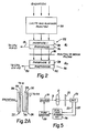
- Figure 2 illustrates a particular layered detector segment structure for use as a component of an energy sensitive radiation detector array D.
- the detector responds to radiation incident upon it, transmitted in a downward direction with respect to Figure 2, to produce two outputs at leads 18, 20.
- the output at lead 18 represents radiation incident upon the detector segment having an energy level in a lower energy range.
- the output at the lead 20 represents the detector seg ment's response to incident x-ray radiation having an energy level in a second, higher energy range.
- the detector segment includes a first elemental layer 22 primarily responsive to lower energy x-rays, and a second elemental layer 24 responsive to higher energy x-rays.
- Each of the layers 22, 24, includes a phosphor coating layer 26, 28, respectively, and a photodiode 30, 32, each respectively optically coupled to the phosphor layers 26, 28.
- preferred phosphor material for the first phosphor layer 26 include yttrium oxysulfide, and zinc cadmium sulfide.
- Alternative phosphors are barium sulfate, barium cadmium sulfate, lanthimum oxysulfide and barium fluorochloride.
- preferred phosphors are gadolinium oxysulfide and cadmium tungstate.
- Alternative phosphor materials for the phosphor layer 28 include calcium tungstate and barium lead sulfate.
- a preferred phosphor coating weight for the first phosphor layer 26 is about 20 to 100 milligrams (mg) per square centimeter (cm2).
- Preferred phosphor coating weights for the second phosphor layer lie in the range from approximately 50 to 1000 mg/cm2.
- a phosphor matrix embodying the detector can consist of either a single integral x-ray intensifying screen, a cellularized intensifying screen, or a cellularized matrix of individual phosphor crystals.
- the segments have equal square dimensions in each layer.
- the dimensions of the individual cell segments, where a cellularized structure is used, are equal to the photodiode matrix array spacing, such that each individual photodiode is congruent with its cell segment.
- the cell segment dimensions are greater in the second layer of the detector than in the first.
- the phosphor material selected for the first phosphor layer 26 have a primary absorber atomic number lying in the range of 39 to 57.
- the corresponding desirable atomic number range for the phosphor materials' primary absorber selected for the second layer 28 is 56 to 83.
- a preferred filter material is one containing copper, such as brass.
- a preferred filter thickness, where brass is used, is approximately 0.5 millimeters (mm).
- the range of practical brass filter thicknesses is from about 0.2 mm to about 1.0 mm.
- Alternative filters can comprise either single or multiple filter elements made of material ranging in atomic number from approximately 24 to 58.
- a desirable energy spectrum for the x-ray source is from about 80 kVp to 150kVp, or even higher, if tube technology permits.
- the degree of spacing between the first and second layers 22, 24 of the detector segment is not particularly critical. Spacing between the first and second layers can suitably vary from almost physical contact to about 3 or more centimeters (cm). The spacing between the filter layer 36 and the first and second layers 22, 24 is not critical either.
- Figure 1C show a side view of the detector array D in a form simplified for clarity.
- Figure 1C is simplified in that it shows only one of the two detector elements or layers which each contain a plurality of detector segments as defined by the dimensions of the photodiodes 12.
- Figure 2A is provided to show the dual detector element (layer) structure which is the present subject.
- Figure 2A shows how the detailed structure of Figure 2 appears, when incorporated into a linear detector array D.
- Figure 2A represents a side view of such an array.
- Figure 2A illustrates the two detector elements or layers 22, 24 one positioned behind the other with respect to the incident radiation from the source.
- Each element includes respectively a coating layer of phosphor 26, 28, and a set of photodiodes respectively indicated at 30, 32. Between the elements is located the filter element 36.
- Each photodiode has a lead emergent therefrom for transmitting its analog radiation indicating signal to the appropriate one of the lead groups 01, 02, as de scribed generally above. For purposes of clarity, only representative leads are shown in Figure 2A.
- the application of the split energy radiation detector of this invention is by no means limited to a linear array of detectors, for use in slit projection digital radiography, the environment described in detail above.
- the present invention can also be embodied in a so-called "area” detector, i.e., a relatively large rectangular radiation detector covering a relatively expansive portion of the patient's body, designed for use with so-called “area” beams, which diverge from the source to expose the radiation detector simultaneously over its entire face.
- area detector i.e., a relatively large rectangular radiation detector covering a relatively expansive portion of the patient's body, designed for use with so-called “area” beams, which diverge from the source to expose the radiation detector simultaneously over its entire face.
- One such area detector includes a first phosphor layer of relatively low atomic number, as described above, coupled to a radiographic film layer, behind which is a second higher atomic number phosphor screen coupled to a second piece of film. Also, instead of the film portions, photoconductive or thermoluminescent plates could be used.
- the present invention is applicable to radiation detector technology employing other than phosphor materials which convert radiation events into light energy.
- the principles of this invention can be incorporated as well into radiation detection technology utilizing other types of radiation sensitive material, such as solid state materials which convert incident radiation into electrical signals which represent radiation incident on the material, without the need for converting such energy to the form of light.
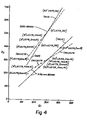
- the arrangement of the first and second detector layers employed in the experiment was in effect as shown in Figure 2.
- a Lucite and aluminum phantom 38 was employed to simulate soft tissue and bone.
- the experimental results are tabulated in Table 1 for a typical 120 kVp radiation level and plotted in Figure 4. Note how the iso-Lucite and iso-aluminum lines are more distinct when the brass filter is inserted between the first and second detector layers. From the data in Table 1 the relative uncertainty in estimating the thickness of Lucite and aluminum can be calculated and these results are tabulated in Table 2. Note that the ability to discriminate Lucite and aluminum is improved when the brass filter is inserted between the first and second detector.
- the first phosphor layer was a 43 mg/cm2 coating of yttrium oxysulfide.
- the second phosphor layer was a 110 mg/cm2 coating of gadolinium oxysulfide.
- a split energy level radiation detector such as illustrated in detail in Figure 2 is also applicable in conventional radiography systems as a phototimer.
- Figure 5 illustrates such a system.
- An x-ray source 50 directs a beam 51 of x-ray through the body of a patient P and onto a conventional radiation screen 52.
- a split level radiation detector 54 constructed in accordance with the structure detailed in Figure 2 is positioned as a phototimer behind the screen to receive that portion of the x-ray energy from the beam 51 which passes through the screen 52.
- the phototimer 54 produces, on leads 53, 55, signals indicating the amount of received energy in separate lower and higher energy ranges, respectively. These separate energy indicating signals are fed to a dual level energy integrator 56.
- the energy integrator 56 includes circuitry for separately integrating the amount of energy, over time, indicated by the outputs on the leads 53, 55.
- the integrator 56 When the integrated energy values developed by the integrator 56 accumulate to a predetermined criteria, the integrator 56 produces a signal to a tube control circuit 58 which terminates operation of the source 50 in response to the accumulation of the particular predetermined integrated energy criterian.
- the energy criterian governing the time of x-ray exposure can be selected in accordance with known principles by those with skill in the art. This criterian can be defined as the accumulation of a predetermined amount of energy in either of the sensed energy ranges, or can be a function of both sensed energy levels.
Landscapes
- Health & Medical Sciences (AREA)
- Life Sciences & Earth Sciences (AREA)
- Engineering & Computer Science (AREA)
- Physics & Mathematics (AREA)
- High Energy & Nuclear Physics (AREA)
- Molecular Biology (AREA)
- Medical Informatics (AREA)
- General Health & Medical Sciences (AREA)
- Biomedical Technology (AREA)
- Spectroscopy & Molecular Physics (AREA)
- Nuclear Medicine, Radiotherapy & Molecular Imaging (AREA)
- Optics & Photonics (AREA)
- General Physics & Mathematics (AREA)
- Surgery (AREA)
- Veterinary Medicine (AREA)
- Heart & Thoracic Surgery (AREA)
- Biophysics (AREA)
- Animal Behavior & Ethology (AREA)
- Pathology (AREA)
- Public Health (AREA)
- Radiology & Medical Imaging (AREA)
- Chemical & Material Sciences (AREA)
- Crystallography & Structural Chemistry (AREA)
- Pulmonology (AREA)
- Theoretical Computer Science (AREA)
- Apparatus For Radiation Diagnosis (AREA)
- Measurement Of Radiation (AREA)
Applications Claiming Priority (2)
| Application Number | Priority Date | Filing Date | Title |
|---|---|---|---|
| US06/444,605 US4626688A (en) | 1982-11-26 | 1982-11-26 | Split energy level radiation detection |
| US444605 | 1982-11-26 |
Related Parent Applications (2)
| Application Number | Title | Priority Date | Filing Date |
|---|---|---|---|
| EP83307157A Division EP0115125B1 (fr) | 1982-11-26 | 1983-11-23 | Détecteurs de rayonnement et dispositif pour la discrimination de l'énergie et méthodes utilisant lesdits détecteurs |
| EP83307157.4 Division | 1983-11-23 |
Publications (2)
| Publication Number | Publication Date |
|---|---|
| EP0270761A2 true EP0270761A2 (fr) | 1988-06-15 |
| EP0270761A3 EP0270761A3 (fr) | 1989-05-31 |
Family
ID=23765594
Family Applications (4)
| Application Number | Title | Priority Date | Filing Date |
|---|---|---|---|
| EP83307157A Expired EP0115125B1 (fr) | 1982-11-26 | 1983-11-23 | Détecteurs de rayonnement et dispositif pour la discrimination de l'énergie et méthodes utilisant lesdits détecteurs |
| EP87114392A Withdrawn EP0287707A3 (fr) | 1982-11-26 | 1983-11-23 | Dispositif pour la discrimination de l'énergie |
| EP87114391A Withdrawn EP0270761A3 (fr) | 1982-11-26 | 1983-11-23 | Système image de rayonnement |
| EP87114390A Withdrawn EP0271655A3 (fr) | 1982-11-26 | 1983-11-23 | Dispositif pour la discrimination de l'énergie |
Family Applications Before (2)
| Application Number | Title | Priority Date | Filing Date |
|---|---|---|---|
| EP83307157A Expired EP0115125B1 (fr) | 1982-11-26 | 1983-11-23 | Détecteurs de rayonnement et dispositif pour la discrimination de l'énergie et méthodes utilisant lesdits détecteurs |
| EP87114392A Withdrawn EP0287707A3 (fr) | 1982-11-26 | 1983-11-23 | Dispositif pour la discrimination de l'énergie |
Family Applications After (1)
| Application Number | Title | Priority Date | Filing Date |
|---|---|---|---|
| EP87114390A Withdrawn EP0271655A3 (fr) | 1982-11-26 | 1983-11-23 | Dispositif pour la discrimination de l'énergie |
Country Status (4)
| Country | Link |
|---|---|
| US (2) | US4626688A (fr) |
| EP (4) | EP0115125B1 (fr) |
| JP (1) | JPS59145983A (fr) |
| CA (1) | CA1217883A (fr) |
Cited By (5)
| Publication number | Priority date | Publication date | Assignee | Title |
|---|---|---|---|---|
| WO1996035372A2 (fr) * | 1995-05-11 | 1996-11-14 | University Of Massachusetts Medical Center | Systeme pour imagerie radiographique quantitative |
| WO2000068710A2 (fr) * | 1999-05-10 | 2000-11-16 | Lippens Francois | Systemes de detection selective d'energie |
| EP1217388A2 (fr) * | 2000-12-22 | 2002-06-26 | GE Medical Systems Global Technology Company LLC | Détecteur numérique à scellement hermétique |
| WO2002065915A1 (fr) * | 2001-02-23 | 2002-08-29 | Koninklijke Philips Electronics N.V. | Procede et e permettant de determiner la densite d'un volume dans un ensemble de donnees d'image |
| US7342233B2 (en) | 2005-11-18 | 2008-03-11 | Sectra Mamea Ab | Method and arrangement relating to x-ray imaging |
Families Citing this family (119)
| Publication number | Priority date | Publication date | Assignee | Title |
|---|---|---|---|---|
| US4626688A (en) | 1982-11-26 | 1986-12-02 | Barnes Gary T | Split energy level radiation detection |
| NL8401946A (nl) * | 1984-06-19 | 1986-01-16 | Optische Ind De Oude Delft Nv | Stelsel voor het detecteren van twee roentgenstralingsenergieen. |
| US4817123A (en) * | 1984-09-21 | 1989-03-28 | Picker International | Digital radiography detector resolution improvement |
| US4709382A (en) * | 1984-11-21 | 1987-11-24 | Picker International, Inc. | Imaging with focused curved radiation detectors |
| DE3517101C1 (de) * | 1985-05-11 | 1986-10-09 | Deutsches Elektronen-Synchrotron Desy, 2000 Hamburg | Vorrichtung zur digitalen Subtraktions-Angiographie im Energiesubstraktions-Modus |
| US4845731A (en) * | 1985-06-05 | 1989-07-04 | Picker International | Radiation data acquistion |
| JPS625336A (ja) * | 1985-07-01 | 1987-01-12 | 松下電器産業株式会社 | X線照射装置 |
| NL8502910A (nl) * | 1985-10-24 | 1987-05-18 | Sipko Luu Boersma | Roentgen doorlichtings beeldvormer. |
| US4980904A (en) * | 1985-11-15 | 1990-12-25 | Picker International, Inc. | Radiation imaging calibration |
| US4780897A (en) * | 1986-05-06 | 1988-10-25 | General Electric Company | Dual energy imaging with kinestatic charge detector |
| IL79733A (en) * | 1986-08-15 | 1990-04-29 | Elscint Ltd | Bone mineral density mapping |
| US4963746A (en) * | 1986-11-25 | 1990-10-16 | Picker International, Inc. | Split energy level radiation detection |
| US4813064A (en) * | 1987-02-09 | 1989-03-14 | Jackson Iii David | Method and apparatus for counterbalancing rotating bodies |
| FR2621705B1 (fr) * | 1987-10-09 | 1990-03-30 | Thomson Csf | Detecteur multiradiations, notamment detecteur de rayons x a double energie |
| US4872188A (en) * | 1987-11-27 | 1989-10-03 | Picker International, Inc. | Registration correction for radiographic scanners with sandwich detectors |
| US5262649A (en) * | 1989-09-06 | 1993-11-16 | The Regents Of The University Of Michigan | Thin-film, flat panel, pixelated detector array for real-time digital imaging and dosimetry of ionizing radiation |
| US4975574A (en) * | 1990-01-05 | 1990-12-04 | Henry Lucas | Method of and apparatus for measuring the mean concentration of thoron and/or radon in a gas mixture |
| DE69104756T2 (de) * | 1990-03-22 | 1995-06-01 | Matsushita Electric Ind Co Ltd | Verfahren zur Feststellung des Massenanteils eines Target- materials mit Hilfe eines mehrkanaligen Röntgen-Bildsensors. |
| US5138167A (en) * | 1991-01-23 | 1992-08-11 | University Of Alabama - Birmingham | Split energy radiation detection |
| US5841832A (en) * | 1991-02-13 | 1998-11-24 | Lunar Corporation | Dual-energy x-ray detector providing spatial and temporal interpolation |
| US5451793A (en) * | 1991-06-20 | 1995-09-19 | Thomas Jefferson University | Binary screen, system and method for single pulse dual energy radiology |
| US5216252A (en) * | 1991-06-20 | 1993-06-01 | Thomas Jefferson University | Binary screen, system and method for single pulse dual energy radiography |
| US5247559A (en) * | 1991-10-04 | 1993-09-21 | Matsushita Electric Industrial Co., Ltd. | Substance quantitative analysis method |
| DE4204116C2 (de) * | 1992-02-12 | 1995-04-06 | Siemens Ag | Röntgendiagnostikeinrichtung |
| US5221843A (en) * | 1992-04-23 | 1993-06-22 | Alvarez Robert E | Active energy selective x-ray image detection |
| US5334843A (en) * | 1992-08-17 | 1994-08-02 | Zeman Herbert D | Composite scintillator screen |
| US5367172A (en) * | 1993-06-01 | 1994-11-22 | E. I. Du Pont De Nemours And Company | Radiological system employing phosphors of different densities |
| US5548123A (en) * | 1994-12-06 | 1996-08-20 | Regents Of The University Of California | High resolution, multiple-energy linear sweep detector for x-ray imaging |
| US5508526A (en) * | 1995-02-01 | 1996-04-16 | Keithley Instruments, Inc. | Dual entrance window ion chamber for measuring X-ray exposure |
| US5747812A (en) * | 1995-11-22 | 1998-05-05 | Picker International, Inc. | Scatter filter for emission tomography |
| DE19711927A1 (de) * | 1997-03-21 | 1998-09-24 | Siemens Ag | Energieselektive Detektoranordnung |
| DE19826062B4 (de) | 1998-06-12 | 2006-12-14 | Smiths Heimann Gmbh | Verfahren und Anordnung zur Detektion von Röntgenstrahlen |
| JP2001099996A (ja) * | 1999-09-29 | 2001-04-13 | Fuji Photo Film Co Ltd | 蓄積性蛍光体シート |
| US6683934B1 (en) | 2000-06-05 | 2004-01-27 | General Electric Company | Dual energy x-ray imaging system and method for radiography and mammography |
| DE10044357A1 (de) | 2000-09-07 | 2002-03-21 | Heimann Systems Gmbh & Co | Detektoranordnung zur Detektion von Röntgenstrahlen |
| US6529573B2 (en) * | 2001-03-09 | 2003-03-04 | The Regents Of The University Of California | Proton recoil scintillator neutron rem meter |
| JP2003065972A (ja) * | 2001-08-23 | 2003-03-05 | Ishida Co Ltd | X線検査装置 |
| DE10143131B4 (de) * | 2001-09-03 | 2006-03-09 | Siemens Ag | Verfahren zur Ermittlung von Dichte- und Ordnungszahlverteilungen bei radiographischen Untersuchungsverfahren |
| US7072440B2 (en) * | 2001-10-19 | 2006-07-04 | Control Screening, Llc | Tomographic scanning X-ray inspection system using transmitted and Compton scattered radiation |
| US7415146B2 (en) * | 2002-04-12 | 2008-08-19 | Ge Medical Systems Global Technology Company, Llc | Method and apparatus to determine bone mineral density utilizing a flat panel detector |
| US7295691B2 (en) * | 2002-05-15 | 2007-11-13 | Ge Medical Systems Global Technology Company, Llc | Computer aided diagnosis of an image set |
| US8275091B2 (en) | 2002-07-23 | 2012-09-25 | Rapiscan Systems, Inc. | Compact mobile cargo scanning system |
| US7963695B2 (en) | 2002-07-23 | 2011-06-21 | Rapiscan Systems, Inc. | Rotatable boom cargo scanning system |
| US7050529B2 (en) * | 2002-07-23 | 2006-05-23 | Ge Medical Systems Global Technolgy Company, Llc | Methods and apparatus for performing a computed tomography scan |
| US6891918B2 (en) * | 2002-11-27 | 2005-05-10 | Ge Medical Systems Global Technology Company, Llc | Methods and apparatus for acquiring perfusion data |
| GB0525593D0 (en) | 2005-12-16 | 2006-01-25 | Cxr Ltd | X-ray tomography inspection systems |
| US8243876B2 (en) | 2003-04-25 | 2012-08-14 | Rapiscan Systems, Inc. | X-ray scanners |
| US6873680B2 (en) * | 2003-05-02 | 2005-03-29 | Siemens Westinghouse Power Corporation | Method and apparatus for detecting defects using digital radiography |
| US6928141B2 (en) | 2003-06-20 | 2005-08-09 | Rapiscan, Inc. | Relocatable X-ray imaging system and method for inspecting commercial vehicles and cargo containers |
| DE10330595A1 (de) * | 2003-07-07 | 2005-02-17 | Siemens Ag | Röntgendetektor und Verfahren zur Herstellung von Röntgenbildern mit spektraler Auflösung |
| US20100135458A1 (en) * | 2003-07-18 | 2010-06-03 | Neeraj Agrawal | X-Ray Apparatus for Bone Density Assessment and Monitoring |
| US8085898B2 (en) * | 2009-05-08 | 2011-12-27 | Osteometer Meditech, Inc. | Apparatus for bone density assessment and monitoring |
| US7010092B2 (en) * | 2003-08-08 | 2006-03-07 | Imaging Dynamics Company Ltd. | Dual energy imaging using optically coupled digital radiography system |
| US7095028B2 (en) * | 2003-10-15 | 2006-08-22 | Varian Medical Systems | Multi-slice flat panel computed tomography |
| US7589326B2 (en) | 2003-10-15 | 2009-09-15 | Varian Medical Systems Technologies, Inc. | Systems and methods for image acquisition |
| US7187748B2 (en) * | 2003-12-30 | 2007-03-06 | Ge Medical Systems Global Technology Company, Llc | Multidetector CT imaging method and apparatus with reducing radiation scattering |
| DE102004001790A1 (de) * | 2004-01-12 | 2005-08-04 | Commodas Daten- Und Systemtechnik Nach Mass Gmbh | Vorrichtung zur Trennung von Schüttgütern |
| US20050161609A1 (en) * | 2004-01-16 | 2005-07-28 | Bjoern Heismann | X-ray detector module for spectrally resolved measurements |
| US7235790B2 (en) * | 2004-02-17 | 2007-06-26 | Ge Medical Systems Global Technology Company, Llc | Methods and apparatus for radiation detection |
| US7099433B2 (en) * | 2004-03-01 | 2006-08-29 | Spectramet, Llc | Method and apparatus for sorting materials according to relative composition |
| US7564943B2 (en) * | 2004-03-01 | 2009-07-21 | Spectramet, Llc | Method and apparatus for sorting materials according to relative composition |
| US20060067472A1 (en) * | 2004-09-30 | 2006-03-30 | Possin George E | Method and apparatus for measuring X-ray energy |
| US7471764B2 (en) | 2005-04-15 | 2008-12-30 | Rapiscan Security Products, Inc. | X-ray imaging system having improved weather resistance |
| EP1877832B1 (fr) * | 2005-04-26 | 2018-02-21 | Koninklijke Philips N.V. | Reseau de detecteurs pour tomographie spectrale par ordinateur |
| EP1876955B1 (fr) * | 2005-04-26 | 2016-11-23 | Koninklijke Philips N.V. | Detecteur a double niveau pour tomographie spectrale par ordinateur |
| CN100573116C (zh) * | 2005-06-01 | 2009-12-23 | 同方威视技术股份有限公司 | 一种用于辐射成像的双阵列探测器模块结构 |
| JP4839050B2 (ja) * | 2005-09-21 | 2011-12-14 | 独立行政法人放射線医学総合研究所 | 多色x線測定装置 |
| WO2007110793A1 (fr) * | 2006-03-28 | 2007-10-04 | Philips Intellectual Property & Standards Gmbh | Unite de balayage, appareil de tomographie et procede de tomographie |
| US7526064B2 (en) | 2006-05-05 | 2009-04-28 | Rapiscan Security Products, Inc. | Multiple pass cargo inspection system |
| EP2052279B1 (fr) * | 2006-08-09 | 2019-09-11 | Koninklijke Philips N.V. | Dispositif et procede pour tomographie spectrale informatisee |
| DE102007020642A1 (de) * | 2007-04-30 | 2008-11-06 | Dürr Dental GmbH & Co. KG | Röntgengerät sowie Sensoreinheit für ein Röntgengerät |
| US7742568B2 (en) * | 2007-06-09 | 2010-06-22 | Spectrum San Diego, Inc. | Automobile scanning system |
| US7683299B2 (en) * | 2007-07-09 | 2010-03-23 | Bio-Rad Laboratories, Inc. | Extended dynamic range system design using a photomultiplier tube and solid state detector |
| US7885372B2 (en) * | 2007-12-07 | 2011-02-08 | Morpho Detection, Inc. | System and method for energy sensitive computed tomography |
| CN101470086B (zh) * | 2007-12-29 | 2012-11-28 | 清华大学 | 探测器装置及具有该探测器装置的ct检查系统 |
| GB0803644D0 (en) | 2008-02-28 | 2008-04-02 | Rapiscan Security Products Inc | Scanning systems |
| GB0803642D0 (en) | 2008-02-28 | 2008-04-02 | Rapiscan Security Products Inc | Drive-through scanning systems |
| GB0803643D0 (en) | 2008-02-28 | 2008-04-02 | Rapiscan Security Products Inc | Mobile scanning systems |
| GB0803640D0 (en) | 2008-02-28 | 2008-04-02 | Rapiscan Security Products Inc | Scanning systems |
| GB0803641D0 (en) | 2008-02-28 | 2008-04-02 | Rapiscan Security Products Inc | Scanning systems |
| US9036779B2 (en) | 2008-02-28 | 2015-05-19 | Rapiscan Systems, Inc. | Dual mode X-ray vehicle scanning system |
| GB0809107D0 (en) | 2008-05-20 | 2008-06-25 | Rapiscan Security Products Inc | Scannign systems |
| GB0809110D0 (en) | 2008-05-20 | 2008-06-25 | Rapiscan Security Products Inc | Gantry scanner systems |
| GB0809109D0 (en) | 2008-05-20 | 2008-06-25 | Rapiscan Security Products Inc | Scanner systems |
| US8963094B2 (en) | 2008-06-11 | 2015-02-24 | Rapiscan Systems, Inc. | Composite gamma-neutron detection system |
| GB0810638D0 (en) | 2008-06-11 | 2008-07-16 | Rapiscan Security Products Inc | Photomultiplier and detection systems |
| US7864037B2 (en) * | 2008-06-16 | 2011-01-04 | International Business Machines Corporation | Pattern-driven communication architecture |
| US8086547B2 (en) * | 2008-06-16 | 2011-12-27 | International Business Machines Corporation | Data pattern generation, modification and management utilizing a semantic network-based graphical interface |
| BRPI0910206A2 (pt) * | 2008-06-30 | 2015-09-29 | Koninkl Philips Electronics Nv | sistema de formação de imagem de tomografia computadorizada e método |
| JP2010190830A (ja) * | 2009-02-20 | 2010-09-02 | Hamamatsu Photonics Kk | 放射線検出装置 |
| US8610019B2 (en) | 2009-02-27 | 2013-12-17 | Mineral Separation Technologies Inc. | Methods for sorting materials |
| US8111803B2 (en) * | 2009-04-29 | 2012-02-07 | General Electric Company | Method for energy sensitive computed tomography using checkerboard filtering |
| US9310323B2 (en) | 2009-05-16 | 2016-04-12 | Rapiscan Systems, Inc. | Systems and methods for high-Z threat alarm resolution |
| JP5467830B2 (ja) * | 2009-09-18 | 2014-04-09 | 浜松ホトニクス株式会社 | 放射線検出装置 |
| JP5457118B2 (ja) | 2009-09-18 | 2014-04-02 | 浜松ホトニクス株式会社 | 放射線検出装置 |
| US8314394B1 (en) | 2009-11-04 | 2012-11-20 | Science Applications International Corporation | System and method for three-dimensional imaging using scattering from annihilation coincidence photons |
| JP2011112623A (ja) * | 2009-11-30 | 2011-06-09 | Ihi Inspection & Instrumentation Co Ltd | 2段x線検出器 |
| GB201004121D0 (en) | 2010-03-12 | 2010-04-28 | Durham Scient Crystals Ltd | Detector device, inspection apparatus and method |
| US8692148B1 (en) | 2010-07-19 | 2014-04-08 | National Recovery Technologies, Llc | Method and apparatus for improving performance in container sorting |
| PL3270185T3 (pl) | 2011-02-08 | 2023-06-12 | Rapiscan Systems, Inc. | Niejawny nadzór z wykorzystaniem wielomodalnościowego wykrywania |
| GB2544687B (en) * | 2011-02-22 | 2017-09-13 | Rapiscan Systems Inc | X-ray inspection system |
| US9218933B2 (en) | 2011-06-09 | 2015-12-22 | Rapidscan Systems, Inc. | Low-dose radiographic imaging system |
| DE102011089595A1 (de) * | 2011-12-22 | 2013-06-27 | Siemens Aktiengesellschaft | Röntgendetektor und Verfahren zur Erzeugung eines Gesamtröntgenbildes |
| US9114433B2 (en) | 2012-01-17 | 2015-08-25 | Mineral Separation Technologies, Inc. | Multi-fractional coal sorter and method of use thereof |
| US9044186B2 (en) | 2012-06-25 | 2015-06-02 | George W. Ma | Portable dual-energy radiographic X-ray perihpheral bone density and imaging systems and methods |
| CN103675931B (zh) * | 2012-09-26 | 2016-09-28 | 同方威视技术股份有限公司 | Ct系统和用于ct系统的探测装置 |
| WO2014121097A1 (fr) | 2013-01-31 | 2014-08-07 | Rapiscan Systems, Inc. | Système d'inspection de sécurité portable |
| US9234838B2 (en) | 2013-04-08 | 2016-01-12 | National Recovery Technologies, Llc | Method to improve detection of thin walled polyethylene terephthalate containers for recycling including those containing liquids |
| US9227229B2 (en) | 2013-04-08 | 2016-01-05 | National Recovery Technologies, Llc | Method to improve detection of thin walled polyethylene terephthalate containers for recycling including those containing liquids |
| US9405021B2 (en) * | 2013-06-03 | 2016-08-02 | Unfors Raysafe Ab | Detector for detecting x-ray radiation parameters |
| US9383472B2 (en) | 2013-12-30 | 2016-07-05 | Halliburton Energy Services, Inc. | Position-sensitive gamma detectors |
| US9557427B2 (en) | 2014-01-08 | 2017-01-31 | Rapiscan Systems, Inc. | Thin gap chamber neutron detectors |
| US10539687B2 (en) | 2014-10-16 | 2020-01-21 | Analogic Corporation | Indirect conversion detector array |
| US11156727B2 (en) * | 2015-10-02 | 2021-10-26 | Varian Medical Systems, Inc. | High DQE imaging device |
| WO2018115287A1 (fr) * | 2016-12-21 | 2018-06-28 | Koninklijke Philips N.V. | Protection d'un détecteur de rayonnement gamma |
| US11000701B2 (en) * | 2017-08-01 | 2021-05-11 | Varex Imaging Corporation | Dual-layer detector for soft tissue motion tracking |
| JP2021076393A (ja) * | 2019-11-05 | 2021-05-20 | キヤノン株式会社 | 放射線撮像装置及び放射線撮像システム |
| WO2022183191A1 (fr) | 2021-02-23 | 2022-09-01 | Rapiscan Systems, Inc. | Systèmes et procédés pour éliminer des signaux de diaphonie dans des systèmes de balayage ayant de multiples sources de rayons x |
| CN113628304B (zh) * | 2021-10-09 | 2021-12-03 | 湖北芯擎科技有限公司 | 图像处理方法、装置、电子设备及存储介质 |
Citations (3)
| Publication number | Priority date | Publication date | Assignee | Title |
|---|---|---|---|---|
| US4029963A (en) * | 1976-07-30 | 1977-06-14 | The Board Of Trustees Of Leland Stanford Junior University | X-ray spectral decomposition imaging system |
| US4247774A (en) * | 1978-06-26 | 1981-01-27 | The United States Of America As Represented By The Department Of Health, Education And Welfare | Simultaneous dual-energy computer assisted tomography |
| WO1981000457A1 (fr) * | 1979-08-08 | 1981-02-19 | Technicare Corp | Detecteur de forme |
Family Cites Families (76)
| Publication number | Priority date | Publication date | Assignee | Title |
|---|---|---|---|---|
| US1624443A (en) | 1921-10-20 | 1927-04-12 | Union Carbide & Carbon Res Lab | X-ray filter |
| US2541599A (en) | 1944-10-31 | 1951-02-13 | Morrison Philip | Radiography |
| US2445305A (en) | 1944-12-13 | 1948-07-13 | Socony Vacuum Oil Co Inc | Radiation detector |
| US3247377A (en) * | 1962-04-12 | 1966-04-19 | Texaco Inc | Scintillation-type well logging device with two crystals responding separately to thermal neutrons and gamma rays |
| US3267283A (en) | 1964-06-04 | 1966-08-16 | Optics Tcchnology Inc | Color display apparatus for images produced in different frequency ranges |
| US3399302A (en) * | 1964-06-19 | 1968-08-27 | North American Rockwell | Gamma radiation sensor and detection system |
| FR1508461A (fr) * | 1966-01-10 | 1968-01-05 | Ibm | Analyseur à rayons x. |
| GB1227749A (fr) | 1967-12-28 | 1971-04-07 | ||
| US3582651A (en) | 1968-08-22 | 1971-06-01 | Westinghouse Electric Corp | X-ray image storage,reproduction and comparison system |
| AT283784B (de) | 1968-10-31 | 1970-08-25 | Oesterr Studien Atomenergie | Comptonspektrometer |
| US3725704A (en) | 1971-01-28 | 1973-04-03 | Lockheed Aircraft Corp | Rare earth phosphors for x-ray conversion screens |
| BE792387A (nl) | 1971-12-31 | 1973-06-07 | Agfa Gevaert Nv | Versterkingsschermen voor rontgenfotografie |
| US3790799A (en) | 1972-06-21 | 1974-02-05 | American Science & Eng Inc | Radiant energy imaging with rocking scanning |
| US3801785A (en) | 1972-11-01 | 1974-04-02 | Raytheon Co | Spatially modulated imaging system |
| US3859527A (en) | 1973-01-02 | 1975-01-07 | Eastman Kodak Co | Apparatus and method for producing images corresponding to patterns of high energy radiation |
| US3894181A (en) | 1973-06-14 | 1975-07-08 | Wisconsin Alumni Res Found | Differential enhancement of periodically variable images |
| US3848130A (en) | 1973-06-25 | 1974-11-12 | A Macovski | Selective material x-ray imaging system |
| US3936638A (en) | 1973-07-06 | 1976-02-03 | Emi Limited | Radiology |
| DE2336652A1 (de) | 1973-07-18 | 1975-01-30 | Siemens Ag | Schichtsystem zur absorption von roentgenstrahlen |
| US3860817A (en) | 1973-08-10 | 1975-01-14 | Gen Electric | Reducing patient X-ray dose during fluoroscopy with an image system |
| GB1489398A (en) * | 1973-12-07 | 1977-10-19 | Minnesota Mining & Mfg | X-ray intensifying screen |
| US3854049A (en) | 1973-12-10 | 1974-12-10 | Wisconsin Alumni Res Found | Compensation for patient thickness variations in differential x-ray transmission imaging |
| US3974386A (en) | 1974-07-12 | 1976-08-10 | Wisconsin Alumni Research Foundation | Differential X-ray method and apparatus |
| US3965358A (en) * | 1974-12-06 | 1976-06-22 | Albert Macovski | Cross-sectional imaging system using a polychromatic x-ray source |
| US4031401A (en) | 1975-03-14 | 1977-06-21 | American Science & Engineering, Inc. | Radiant energy imaging scanning |
| US4008400A (en) | 1975-03-18 | 1977-02-15 | Picker Corporation | Transverse tomography system having multibeam orbital scanning with all beams offset from the center of orbit |
| JPS522777A (en) | 1975-06-24 | 1977-01-10 | Jeol Ltd | Radiation detector |
| US4047037A (en) | 1976-02-09 | 1977-09-06 | The Ohio State University | Gamma ray camera for nuclear medicine |
| US4055765A (en) | 1976-04-27 | 1977-10-25 | The Ohio State University | Gamma camera system with composite solid state detector |
| US4055766A (en) | 1976-04-27 | 1977-10-25 | The Ohio State University | Control system for gamma camera |
| GB1516032A (en) * | 1976-04-13 | 1978-06-28 | Bfg Glassgroup | Coating of glass |
| US4037104A (en) | 1976-04-29 | 1977-07-19 | Nucleonic Data Systems, Inc. | Dual beam X-ray thickness gauge |
| US4047029A (en) | 1976-07-02 | 1977-09-06 | Allport John J | Self-compensating X-ray or γ-ray thickness gauge |
| US4217498A (en) | 1976-09-13 | 1980-08-12 | General Electric Company | Tomographic scanning apparatus with ionization detector means |
| NL7703944A (en) * | 1977-04-12 | 1978-10-16 | Philips Nv | Multichannel X=ray detector esp. for computer tomography - has cells of differing measuring capacity increasing speed and accuracy |
| DE2717349A1 (de) * | 1977-04-19 | 1978-10-26 | Siemens Ag | Roentgenschichtgeraet zur herstellung von transversalschichtbildern |
| JPS5425189A (en) * | 1977-07-28 | 1979-02-24 | Toshiba Corp | X-ray tomogram diagnosis unit |
| US4179100A (en) | 1977-08-01 | 1979-12-18 | University Of Pittsburgh | Radiography apparatus |
| NL7710052A (nl) | 1977-09-14 | 1979-03-16 | Philips Nv | Inrichting voor computer-tomografie. |
| US4234792A (en) * | 1977-09-29 | 1980-11-18 | Raytheon Company | Scintillator crystal radiation detector |
| US4670892A (en) | 1977-11-15 | 1987-06-02 | Philips Medical Systems, Inc. | Method and apparatus for computed tomography of portions of a body plane |
| US4187427A (en) | 1978-01-09 | 1980-02-05 | General Electric Company | Structure for collimated scintillation detectors useful in tomography |
| US4255666A (en) * | 1979-03-07 | 1981-03-10 | Diagnostic Information, Inc. | Two stage, panel type x-ray image intensifier tube |
| US4242583A (en) | 1978-04-26 | 1980-12-30 | American Science And Engineering, Inc. | X-ray imaging variable resolution |
| US4217641A (en) | 1978-04-28 | 1980-08-12 | U.S. Philips Corporation | Correction for polychromatic X-ray distortion in CT images |
| US4204226A (en) | 1978-05-16 | 1980-05-20 | Wisconsin Alumni Research Foundation | Real-time digital X-ray time interval difference imaging |
| US4204225A (en) | 1978-05-16 | 1980-05-20 | Wisconsin Alumni Research Foundation | Real-time digital X-ray subtraction imaging |
| JPS54179782U (fr) | 1978-06-09 | 1979-12-19 | ||
| JPS5512429A (en) | 1978-07-12 | 1980-01-29 | Fuji Photo Film Co Ltd | Radioactive image reader |
| DE2831038C2 (de) * | 1978-07-14 | 1982-07-01 | Siemens AG, 1000 Berlin und 8000 München | Strahlendiagnostikgerät für die Erzeugung von Schichtbildern |
| US4260898A (en) | 1978-09-28 | 1981-04-07 | American Science And Engineering, Inc. | X-ray imaging variable resolution |
| JPS5546408A (en) | 1978-09-29 | 1980-04-01 | Toshiba Corp | X-ray device |
| US4267446A (en) * | 1979-04-03 | 1981-05-12 | Geoco, Inc. | Dual scintillation detector for determining grade of uranium ore |
| CA1117228A (fr) * | 1979-08-27 | 1982-01-26 | Montreal Neurological Institute | Dispositif de visualisation d'annihilations positoniques utilisant plusieurs anneaux de detecteurs decales |
| FR2468999A1 (fr) * | 1979-10-30 | 1981-05-08 | Thomson Csf | Detecteur de rayonnement a photodiode, a capacite reduite, et dispositif de prise de vues comprenant un tel detecteur |
| US4266425A (en) | 1979-11-09 | 1981-05-12 | Zikonix Corporation | Method for continuously determining the composition and mass flow of butter and similar substances from a manufacturing process |
| US4472822A (en) | 1980-05-19 | 1984-09-18 | American Science And Engineering, Inc. | X-Ray computed tomography using flying spot mechanical scanning mechanism |
| US4366382B2 (en) | 1980-09-09 | 1997-10-14 | Scanray Corp | X-ray line scan system for use in baggage inspection |
| US4426721A (en) | 1980-10-07 | 1984-01-17 | Diagnostic Information, Inc. | X-ray intensifier detector system for x-ray electronic radiography |
| NL8006216A (nl) * | 1980-11-13 | 1982-06-01 | Philips Nv | Golflengtegevoelig stralingsonderzoekapparaat. |
| JPS57122850A (en) * | 1981-01-23 | 1982-07-30 | Tokyo Shibaura Electric Co | Radioactive ray tomogram photograph apparatus |
| US4445226A (en) | 1981-05-05 | 1984-04-24 | The Board Of Trustees Of The Leland Stanford Junior University | Multiple-energy X-ray subtraction imaging system |
| US4413353A (en) | 1981-09-03 | 1983-11-01 | Albert Macovski | X-Ray encoding system using an optical grating |
| DE3140145A1 (de) * | 1981-10-09 | 1983-04-21 | Heimann Gmbh, 6200 Wiesbaden | Vorrichtung zur herstellung eines roentgenbildes von koerpern |
| US4578803A (en) | 1981-12-07 | 1986-03-25 | Albert Macovski | Energy-selective x-ray recording and readout system |
| DE3272633D1 (en) | 1981-12-30 | 1986-09-18 | Plessey Overseas | Electro-acoustic transducers |
| DE89665T1 (de) * | 1982-03-20 | 1984-05-10 | Fuji Photo Film Co., Ltd., Minami Ashigara, Kanagawa | System und anordnung zum subtrahieren von roentgenbildern. |
| US4425426A (en) | 1982-09-30 | 1984-01-10 | Eastman Kodak Company | Radiographic elements exhibiting reduced crossover |
| GB2130835A (en) | 1982-10-04 | 1984-06-06 | Andrzej Kamil Drukier | Apparatus for the diagnosis of body structures into which a gamma-emitting radioactive isotape has been introduced |
| JPS5983486A (ja) | 1982-11-04 | 1984-05-14 | Fuji Photo Film Co Ltd | 放射線画像のエネルギ−・サブトラクシヨン方法およびその方法に用いられる蓄積性螢光体シ−ト、蓄積性螢光体シ−ト積層体並びに蓄積性螢光体シ−トフイルタ積層体 |
| US4626688A (en) | 1982-11-26 | 1986-12-02 | Barnes Gary T | Split energy level radiation detection |
| US4511799A (en) * | 1982-12-10 | 1985-04-16 | American Science And Engineering, Inc. | Dual energy imaging |
| JPS59200983A (ja) | 1983-04-28 | 1984-11-14 | Toshiba Corp | 放射線検出器 |
| US4639599A (en) | 1984-05-10 | 1987-01-27 | Kabushiki Kaisha Toshiba | Ring type single-photon emission CT imaging apparatus |
| US4963746A (en) | 1986-11-25 | 1990-10-16 | Picker International, Inc. | Split energy level radiation detection |
| US4947412A (en) | 1988-10-20 | 1990-08-07 | Picker International, Inc. | X-ray detector for CT scanners |
-
1982
- 1982-11-26 US US06/444,605 patent/US4626688A/en not_active Ceased
-
1983
- 1983-11-16 CA CA000441266A patent/CA1217883A/fr not_active Expired
- 1983-11-23 EP EP83307157A patent/EP0115125B1/fr not_active Expired
- 1983-11-23 EP EP87114392A patent/EP0287707A3/fr not_active Withdrawn
- 1983-11-23 EP EP87114391A patent/EP0270761A3/fr not_active Withdrawn
- 1983-11-23 EP EP87114390A patent/EP0271655A3/fr not_active Withdrawn
- 1983-11-24 JP JP58221353A patent/JPS59145983A/ja active Pending
-
1997
- 1997-03-04 US US08/811,787 patent/USRE37536E1/en not_active Expired - Lifetime
Patent Citations (3)
| Publication number | Priority date | Publication date | Assignee | Title |
|---|---|---|---|---|
| US4029963A (en) * | 1976-07-30 | 1977-06-14 | The Board Of Trustees Of Leland Stanford Junior University | X-ray spectral decomposition imaging system |
| US4247774A (en) * | 1978-06-26 | 1981-01-27 | The United States Of America As Represented By The Department Of Health, Education And Welfare | Simultaneous dual-energy computer assisted tomography |
| WO1981000457A1 (fr) * | 1979-08-08 | 1981-02-19 | Technicare Corp | Detecteur de forme |
Cited By (10)
| Publication number | Priority date | Publication date | Assignee | Title |
|---|---|---|---|---|
| US6717174B2 (en) | 1989-12-05 | 2004-04-06 | University Of Massachusetts Medical Center | System for quantitative radiographic imaging |
| WO1996035372A2 (fr) * | 1995-05-11 | 1996-11-14 | University Of Massachusetts Medical Center | Systeme pour imagerie radiographique quantitative |
| WO1996035372A3 (fr) * | 1995-05-11 | 1997-01-30 | Univ Massachusetts Medical | Systeme pour imagerie radiographique quantitative |
| WO2000068710A2 (fr) * | 1999-05-10 | 2000-11-16 | Lippens Francois | Systemes de detection selective d'energie |
| WO2000068710A3 (fr) * | 1999-05-10 | 2001-04-12 | Francois Lippens | Systemes de detection selective d'energie |
| EP1217388A2 (fr) * | 2000-12-22 | 2002-06-26 | GE Medical Systems Global Technology Company LLC | Détecteur numérique à scellement hermétique |
| EP1217388A3 (fr) * | 2000-12-22 | 2006-07-05 | GE Medical Systems Global Technology Company LLC | Détecteur numérique à scellement hermétique |
| WO2002065915A1 (fr) * | 2001-02-23 | 2002-08-29 | Koninklijke Philips Electronics N.V. | Procede et e permettant de determiner la densite d'un volume dans un ensemble de donnees d'image |
| US6574302B2 (en) | 2001-02-23 | 2003-06-03 | Koninklijke Philips Electronics N.V. | Method and system for determining a density of a volume in an image data set |
| US7342233B2 (en) | 2005-11-18 | 2008-03-11 | Sectra Mamea Ab | Method and arrangement relating to x-ray imaging |
Also Published As
| Publication number | Publication date |
|---|---|
| EP0271655A2 (fr) | 1988-06-22 |
| USRE37536E1 (en) | 2002-02-05 |
| CA1217883A (fr) | 1987-02-10 |
| EP0287707A2 (fr) | 1988-10-26 |
| EP0115125A1 (fr) | 1984-08-08 |
| JPS59145983A (ja) | 1984-08-21 |
| US4626688A (en) | 1986-12-02 |
| EP0270761A3 (fr) | 1989-05-31 |
| EP0115125B1 (fr) | 1989-10-11 |
| EP0287707A3 (fr) | 1989-06-07 |
| EP0271655A3 (fr) | 1989-06-28 |
Similar Documents
| Publication | Publication Date | Title |
|---|---|---|
| US4626688A (en) | Split energy level radiation detection | |
| US5138167A (en) | Split energy radiation detection | |
| US4963746A (en) | Split energy level radiation detection | |
| EP0182529B1 (fr) | Système de radiographie | |
| US4179100A (en) | Radiography apparatus | |
| US7105828B2 (en) | Hybrid x-ray detector | |
| US5150394A (en) | Dual-energy system for quantitative radiographic imaging | |
| EP0112469B1 (fr) | Méthode de traitement d'image de rayonnement par soustraction en fonction d'énergie, écran luminescent stimulable et filtre composite utilisés pour ladite méthode | |
| Fraser et al. | Digital radiography of the chest: clinical experience with a prototype unit. | |
| US6717174B2 (en) | System for quantitative radiographic imaging | |
| US5864146A (en) | System for quantitative radiographic imaging | |
| US3790785A (en) | Radiographic imaging | |
| EP0785674A1 (fr) | Appareil radiographique et procédé de traitement d'images | |
| EP1462054B1 (fr) | Appareil de radiographie | |
| McDavid et al. | Digital imaging in rotational panoramic radiography. | |
| Sashin et al. | Diode array digital radiography: initial clinical experience | |
| CA2254877A1 (fr) | Systeme d'imagerie radiographique quantitative | |
| Moores | Digital X-ray imaging | |
| Hynes et al. | Radiation dose implications of digital angiographic systems | |
| Plenkovich et al. | Electronic scanning‐slit fluorography: Design and performance of a prototype unit | |
| Slasky et al. | Digital radiography of the chest by self-scanning linear diode arrays | |
| JPH087389B2 (ja) | X線画像のエネルギー・サブトラクシヨン方法およびその方法に用いられる積層体 | |
| CA1131805A (fr) | Appareil de radiographie | |
| AU682944B2 (en) | Screen film cassette | |
| Sashin et al. | Improved Diagnostic Radiography and Reduced Radiation Exposure Using a 1024× 1024 Pixels Linear Diode Array Imaging System |
Legal Events
| Date | Code | Title | Description |
|---|---|---|---|
| PUAI | Public reference made under article 153(3) epc to a published international application that has entered the european phase |
Free format text: ORIGINAL CODE: 0009012 |
|
| AC | Divisional application: reference to earlier application |
Ref document number: 115125 Country of ref document: EP |
|
| AK | Designated contracting states |
Kind code of ref document: A2 Designated state(s): DE FR GB NL |
|
| PUAL | Search report despatched |
Free format text: ORIGINAL CODE: 0009013 |
|
| AK | Designated contracting states |
Kind code of ref document: A3 Designated state(s): DE FR GB NL |
|
| 17P | Request for examination filed |
Effective date: 19891030 |
|
| 17Q | First examination report despatched |
Effective date: 19900924 |
|
| STAA | Information on the status of an ep patent application or granted ep patent |
Free format text: STATUS: THE APPLICATION IS DEEMED TO BE WITHDRAWN |
|
| 18D | Application deemed to be withdrawn |
Effective date: 19910509 |
|
| RIN1 | Information on inventor provided before grant (corrected) |
Inventor name: BARNES, GARY T. |