EP0269980A2 - Datenprozessor zur parallelen Ausführung von miteinander im Konflikt stehenden Befehlen - Google Patents
Datenprozessor zur parallelen Ausführung von miteinander im Konflikt stehenden Befehlen Download PDFInfo
- Publication number
- EP0269980A2 EP0269980A2 EP87117331A EP87117331A EP0269980A2 EP 0269980 A2 EP0269980 A2 EP 0269980A2 EP 87117331 A EP87117331 A EP 87117331A EP 87117331 A EP87117331 A EP 87117331A EP 0269980 A2 EP0269980 A2 EP 0269980A2
- Authority
- EP
- European Patent Office
- Prior art keywords
- instruction
- operand
- succeeding
- instructions
- arithmetic
- Prior art date
- Legal status (The legal status is an assumption and is not a legal conclusion. Google has not performed a legal analysis and makes no representation as to the accuracy of the status listed.)
- Granted
Links
- 238000003860 storage Methods 0.000 claims abstract description 37
- 238000001514 detection method Methods 0.000 claims abstract description 20
- 238000010586 diagram Methods 0.000 description 12
- 238000000034 method Methods 0.000 description 11
- 101000583218 Drosophila melanogaster Protein krasavietz Proteins 0.000 description 8
- 230000014759 maintenance of location Effects 0.000 description 5
- 230000002401 inhibitory effect Effects 0.000 description 3
- 238000007796 conventional method Methods 0.000 description 1
- 238000001427 incoherent neutron scattering Methods 0.000 description 1
- 230000005764 inhibitory process Effects 0.000 description 1
- 230000001360 synchronised effect Effects 0.000 description 1
Images


Classifications
-
- G—PHYSICS
- G06—COMPUTING; CALCULATING OR COUNTING
- G06F—ELECTRIC DIGITAL DATA PROCESSING
- G06F9/00—Arrangements for program control, e.g. control units
- G06F9/06—Arrangements for program control, e.g. control units using stored programs, i.e. using an internal store of processing equipment to receive or retain programs
- G06F9/30—Arrangements for executing machine instructions, e.g. instruction decode
- G06F9/38—Concurrent instruction execution, e.g. pipeline, look ahead
- G06F9/3836—Instruction issuing, e.g. dynamic instruction scheduling or out of order instruction execution
Definitions
- the present invention relates to a data processor for parallelly executing plural instructions, and more particularly to a data processor suitable for executing plural instructions in a pipeline processing system (advanced control system).
- a preceding instruction writes an operation result in a register and a succeeding instruction uses the content of the same register to calculate an address
- the succeeding instruction cannot start address calculation until the preceding instruction has written the operation result in the register, thus causing a delay in the processing.
- address conflict Such contention of data to be used in calculating an address
- a preceding instruction is a so-called load instruction which writes a read-out operand in a register without subjecting it to arithmetic or logical operation and a succeeding instruction becomes in address conflict with the preceding instruction
- a method of reducing a delay in the processing has been proposed as in JP-A-56-46170 in the name of the present assignee.
- a short path for supplying an operation result of a preceding instruction to the input of an arithmetic or logical unit (ALU) is provided at an intermediate of a write path of the ALU to a general purpose register, whereby the arithmetic or logical operation of a succeeding instruction which requires an operation result of the preceding instruction is performed without waiting for such a time when the operation result has been written in a designated general-purpose register.
- ALU arithmetic or logical unit
- a preceding instruction is an instruction such as a LOAD instruction which requires no operation by an ALU
- the operation of a succeeding instruction cannot start until the operation stage of the LOAD instruction has completed.
- a data processor which comprises a storage and a general register group for storing operands, operand hold means for storing operands read from said storage for a plurality of instructions and providing at least two operands; operand select means connected to said operand hold means and said general register group for selecting either one of the operands for a preceding instruction and a succeeding instruction; at least one arithmetic or logical means connected to said operand select means for performing an arithmetic or logical operation on selected operands; decode means for sequentially decoding instructions to be executed and generating instruction decode informations; instruction hold means for storing a plurality of instruction decode informations generated by said decode means and providing at least two instruction decode informations; instruction detection means for detecting that a succeeding instruction writes a read-out operand into said general register group without subjecting it to arithmetic or logical operation, in accordance with instruction decode informations provided by said instruction hold means; conflict detection means for detecting a conflicting state that
- said instruction detection means detects that a preceding instruction writes an operand into the general register group without subjecting it to arithmetic or logical operation, in accordance with instruction decode informations provided by said instruction hold means, said at least one arithmetic or logical means performs at least arithmetic or logical operations of the preceding and succeeding instructions at the same time.
- said operand select means supplies the operand for the preceding instruction to said at least one arithmetic or logical means which performs arithmetic or logical operation of the succeeding instruction, and said at least one arithmetic or logical means performs arithmetic or logical operations of the preceding instruction and the succeeding instructions at the same time.
- said contention detection means detects a contention state that the preceding instruction performs a write operation into a general register of the general register group and the succeeding instruction also performs a write operation into the same general register, in accordance with instruction decode informations provided by said instruction hold means, said contention detection means inhibits the write operation by the preceding instruction into the same general register.
- Fig. 1 is a block diagram showing an overall structure of an embodiment of the data processor according to this invention.
- the pipeline processing system executes two instructions in parallel.
- a prior art for writing two instructions into two instruction registers of the pipeline processing system is disclosed, for example, in JP-A-58-176751.
- an instruction readout circuit 8 reads two instructions to be processed and sets them at instruction registers 10 and 11.
- the instruction register 10 holds a preceding instruction, while the instruction register 11 holds a succeeding instruction.
- An instruction decoder 20 (21) decodes a preceding (succeeding) instruction to generate instruction decode information used for controlling the circuitry of the data processor.
- An instruction queue 30 sequentially holds instruction decode informations generated by the instruction decoders 20 and 21 until a corresponding instruction starts being subjected to arithmetic or logical operation.
- An address adder 40 (41) calculates a logical address of a storage operand for a preceding (succeeding) instruction to be read from a buffer storage 50 (51).
- the buffer storages 50 and 51 hold instructions and data to be processed.
- An operand buffer 60 sequentially holds storage operands read from the buffer storages 50 and 51 until a corresponding instruction starts being subjected to arithmetic or logical operation.
- a general purpose register group 70 is constructed of a group of registers and mainly holds data (such as register operand, address modifying data and the like) frequently used.
- An ALU 80 (81) performs arithmetic or logical operation designated by a preceding (succeeding) instruction.
- a wrap control circuit 90 and an ALU control circuit 95 are necessary for realizing the present invention and are described later in detail.
- Figs. 2A and 2B are timing charts illustrating the standard flow of executing instructions in a pipeline processing system, wherein the abscissa represents a time basis.
- the time basis is graduated in units of cycles, each cycle being referred to as C0, C1, C2, ... in this order starting from an initial cycle (at the left end in the chart).
- Fig. 2A shows the flow of executing instructions wherein an instruction is sequentially processed one by one
- Fig. 2B shows the flow of executing instructions wherein two instructions are sequentially processed in parallel.
- the instruction processing is divided into a plurality of process stages, each process stage being sequentially presented to a plurality of instructions and operated in parallel with others.
- Fig. 2B first an instruction n and an instruction n+1 undergo stage D at cycle C0.
- the instructions n and n+1 then advance to stage A at cycle C1 whereat two instructions immediately after the two instructions n and n+1 start being processed at stage D.
- An instruction is processed at each stage called D, A, L, E and P stage in this order for a unit cycle time.
- D, A, L, E and P stage In this order, referring back to Fig. 1, at stage D instructions held in the instruction registers 10 and 11 are decoded by the instruction decoders 20 and 21 and undergo address calculation by the address adders 40 and 41 to obtain the logical addresses of corresponding storage operands.
- stage A translation from logical addresses to physical addresses and reading of storage operands are carried out at the buffer storages 50 and 51.
- the storage operands read from the buffer storages 50 and 51 are transferred to the operand buffer 60 and then to the ALUs 80 and 81.
- Register operands are also read from the general register group 70 and transferred to the ALUs 80 and 81.
- the above operations provide a preparation for starting arithmetic or logical operations designated by instructions to be executed by the ALUs 80 and 81.
- arithmetic operation is executed by the ALUs 80 and 81.
- the operation results from the ALUs 80 and 81 are written into the general register group 70.
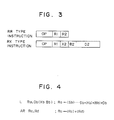
- FIG. 3 shows instruction formats called an RR type and an RX type.
- An RR type instruction is composed of an OP field, R1 field and R2 field.
- An RX type instruction is composed of an OP field, R1 field, X2 field, B2 field and D2 field.
- the OP field indicates the type of arithmetic or logical operation to be executed by the ALUs 80 or 81.
- the R1, R2, X2 and B2 fields each indicate a register in the general register group 70.
- the R1 and R2 fields indicate the registers in which first and second operands are stored, respectively.
- the contents of the registers designated by the X2 and B2 fields are added to the content of the D2 field by the address address 40 or 41 to produce a logical address of a second operand stored in the buffer storages 50 or 51.
- first and second operands are read and subjected to arithmetic or logical operation to thereafter write the operation result into the register which stored the first operand.
- a second operand is read and directly written in the register designated by the first operand without performing arithmetic or logical operation.
- Fig. 4 shows an example of a series of instructions using a so-called LOAD instruction as a preceding instruction.
- the logical address Sb of the second operand (Sb) stored in the storage can be obtained by adding the contents (Xb) and (Bb) of the registers designated by Xb and Bb to the value Db itself.
- the preceding instruction L writes the second operand (Sb) designated by the logical address Sb into a register Ra.
- a succeeding instruction AR herein used as an example is an addition instruction between registers.
- the first operand is the content (Rc) of a register designated by Rc
- the second operand is the content (Rd) of a register designated by Rd.
- Figs. 5A to 5D are timing charts showing the flow of executing two instructions in parallel including the series of instructions shown in Fig. 4.
- the timing chart shown in Fig. 5A illustrates the case where there occurs no operand conflict (Rc ⁇ Ra and Rd ⁇ Ra) between the preceding instruction L and the succeeding instruction AR shown in Fig. 4.
- the flow of executing instructions is the same as the standard one in the pipeline processing shown in Fig. 2B, thus providing no delay in the processing.
- at least one of the operands [(Rc) and (Rd)] to be read by the succeeding instruction AR is the content written in the register Ra by the preceding instruction L.
- Stage P where the preceding instruction performs a write operation into the register Ra is carried out during cycle C4. Therefore, stage L where the succeeding instruction AR reads the operands from the registers Rc and Rd cannot start up to cycle C4.
- stage E where arithmetic or logical operation is performed. There arises two cycle delay in the processing of AR and following instructions as compared to the case of no operand conflict.
- operand wrap-around enables to read the operand not from the register but from the short path, at stage L of the succeeding instruction AR. The operand to be read from the short path can be identified at the latest before stage E during cycle C3 has been fully completed. Therefore, stage L of the succeeding instruction AR can be finished by cycle C3. Now, consider stage E where arithmetic or logical operation is performed. There arises one cycle delay in the processing of AR and following instructions as compared to the case of no operand conflict.
- the second operand (Sb) of the preceding instruction L read from the buffer storage and written into the operand buffer is directly written into the register Ra without being subjected to arithmetic or logical operation by the ALU. Therefore, in the case of operand conflict between the preceding instruction L and the succeeding instruction AR, the operand (Ra) read from the register Ra by the succeeding instruction AR is identical to the operand (Sb) read by the preceding instruction L from the buffer storage and written into the operand buffer.
- the succeeding instruction AR can read the operand, not from the register of the general register group in which the preceding instruction L writes the operation result but from the resource (in this case, operand buffer) from which the preceding instruction read the operand.
- the succeeding instruction AR can read at stage L the operand not from the general register group but from the operand buffer.
- the operand to be read from the operand buffer can be identified at the latest before stage L of the preceding instruction L during cycle C2 has been completed. Therefore, stage L of the succeeding instruction AR can be finished by cycle C2.
- stage E where arithmetic or logical operation is performed. It is possible to process the AR and following instructions at same cycles as those in the case of no operand conflict.
- signals associated with a preceding instruction is represented by a symbol with suffix p and those associated with a succeeding instruction by a symbol with suffix s , to make them distinguishable.
- a preceding instruction INSp (succeeding instruction INSs) set at the instruction register 10 (11) by the instruction readout circuit 8 is decoded and subjected to address calculation.
- the OP field OPp (OPs) of an instruction is decoded by the instruction decoder 20 (21) to generate instruction decode information DECp (DECs) which is used to control associated elements in the processor.
- DECp (DECs) which are relevant to the present invention are shown in the following: OPp (OPs... designates the type of arithmetic or logical operation to be executed by the ALU 80 or 81.
- N1p (n1s) ... indicates that a first operand is read from the general register group 70.
- N2p (n2s) ... indicates that a second operand is read from the general register group 70.
- CHp (CHs) ... indicates that an operation result is written into the general register group 70.
- LDp (LDs)... indicates a LOAD instruction (for transferring a second operand in the storage or in a register to another register).
- BPp (BPs)... identifies the entry of the operand buffer 60 where an operand read from the buffer storage 50 (51) is held.
- the instruction decode informations DECp (DECs) include further the following informations:
- the R1 field R1p (R1s) of an instruction identifies a register of the general register group 70 from which a first operand is read and into which an operation result is written.
- the R2 field R2p (R2s) thereof identifies a register of the general register group 70 from which a second operand is read.
- the X2 field X2p (X2s) and the B2 field B2p (B2s) thereof identify registers of the general register group 70 which are used to calculate a logical address S2p (S2s) of an operand to be read from the buffer storage 50 (51).
- the above-described instruction decode informations DECp (DECs) are sequentially stored in the instruction queue 30.
- the logical address S2p (S2s) of an operand to be read from the buffer storage 50 (51) is calculated by the address adder 40 (41).
- the contents X2pC and B2pC (X2sC and B2sC) of the registers of the general register group 70 respectively identified by the X2 field X2p (X2s) the B2 field B2p (B2s) of the instruction are added to the D2 field D2p (D2s) by the address adder 40 (41) and the result is sent to the buffer storage 50 (51).
- the instruction decode information BPp (BPs) which identifies the entry of the operand buffer 60 where a read-out operand is held.
- the buffer storage 50 (51) When the buffer storage 50 (51) receives the logical address S2p (S2s) of the operand to be read, it translates the logical address into a physical address at stage A and reads the operand S2pC (S2sC) which together with the received instruction decode information BPp (BPs), is sent to the operand buffer 60.
- the buffer storage 50 (51) is generally a high speed and small capacity storage and is used in combination with a low speed and large capacity main storage 52. If an operand to be read is present in the buffer storage 50 (51), it is possible to read the operand in one cycle. However, if an operand to be read is not present in the buffer storage 50 (51), it takes several cycles because the associated operand must be read from the main storage 52, thus leading to a delay in the processing time at stage A.
- the operand buffer 60 receives at stage L the operand S2pC (S2sC) sent from the buffer storage 50 (51) and the instruction decode information BPp (BPs).
- the received operand S2pC (S2sC) is held at the entry of the operand buffer 60 identified by the instruction decode information BPp (BPs).
- An instruction is executed by the ALUs 80 and 81 on the condition that the instruction decode informations DECp (DECs) are held in the instruction queue 30, an operand S2pC (S2sC) to be read, if the instruction is RX type, from the buffer storage 50 (51) is held in the operand buffer 60, and the ALUs 80 and 81 has completed arithmetic or logical operations of the preceding instruction. If such conditions are met, various control signals of the instruction decode informations DECp (DECp) are sent from the instruction queue 30 to the associated elements of the information processor.
- One of the operand S2pC (S2sC) read from the operand buffer 60 and the operand R2pC (R2sC) read from the general register group 70 is selected by a selector 84 (85) which is controlled by the instruction decode information N2p (N2s) sent from the instruction queue 30, the selected one serving as the second operand OP2p (OP2s).
- the instruction decode information OPp (OPs) representative of the type of arithmetic on logical operation is sent to the ALU 80 (81) via the ALU control circuit 95.
- the operand of the succeeding instruction is sent to the ALU 81 via selectors 87 and 89 which are controlled by the wrap control circuit 90.
- the present invention is realized mainly by the wrap control circuit 90, ALU control circuit 95 and selectors 87 and 89, the details of which are described later.
- the ALU 80 (81) executes at stage E an arithmetic or logical operation designated by the instruction decode information OPp (OPs), using the first operand R1pC (WO1s) and the second operand OP2p (WO2s) to obtain an operation result.
- OPp instruction decode information
- WO1s first operand R1pC
- WO2s second operand OP2p
- the instruction queue 30 is provided in order to hold the instruction decode informations during the time from when an instruction has been decoded by the instruction decoder 20 or 21 to when an arithmetic or logical operation starts at the ALU 80 or 81.
- the operation of the instruction queue 30 will now be described in detail hereinafter.
- the instruction queue 30 undergoes a first-in first-out (FIFO) control by means of in-pointers and out-pointers.
- the instruction queue 30 is provided with two in-pointers 32 and 33 and two out-pointers 36 and 37.
- QIPp (QIPs) from the in-pointer 32 (33) indicates the entry where the instruction decode informations sent from the instruction decoder 20 (21) is held.
- QOPp (QOPs) from the out-pointer 36 (37) indicates the entry where the instruction decode informations to be sent to the associated elements in the data processor when an arithmetic operation by the ALU 80 (81) starts are held.
- QIPs from the in-pointer 33 and QOPs from the out-pointer 37 are controlled such that they always indicate the next entries to those indicated by QIPp from the in-pointer 32 and QOPp from the out-pointer 36, respectively. In this concern, it is possible to unite the two in-pointers and two out-pointers into one in-pointer and one out-pointer, respectively.
- the instruction decoders 20 and 21 After the instruction decoders 20 and 21 have decoded instructions held in the instruction registers 10 and 11, they send the instruction decode informations DECp and DECs to the instruction queue 30, and decode end signals DSp and DSs to the in-pointers 32 and 33.
- the in-pointers 32 and 33 are incremented by two. If the instruction decoder 20 alone sends the decode end signal DSp, then the in-pointers 32 and 33 are incremented by one. If the instruction decoder 20 does not send the decode end signal DSp, the decode end signal DSs delivered by the instruction decoder 21 is inhibited, and the in-pointers 32 and 33 are not incremented.
- the ALU control circuit 95 delivers the write enable signals WPp and WPs to the general register group 70 to write therein the operation results RSTp and RSTs, and delivers arithmetic or logical operation end signals EOPp and EOPs for the ALUs 80 and 81 to the out-pointers 36 and 37.
- the ALU control circuit 95 delivers both the operation end signals EOPp and EOPs for the ALUs 80 and 81, the out-pointers 36 and 37 are incremented by two.
- the ALU control circuit 95 delivers only the operation end signal EOPp for the ALU 80, the out-pointers 36 and 37 are incremented by one.
- the wrap control circuit 90 controls to detect oeprand conflict and eliminate a delay in the processing to be caused by operand conflict.
- Fig. 6 is a block diagram showing the internal structure of the wrap control circuit 90.
- Instruction decode informations for preceding and succeeding instructions for use in performing arithmetic or logical operation at the next cycle are sent to the wrap control circuit 90 from the instruction queue 30.
- the instruction decode informations for the preceding instruction have been held in the instruction queue 30 at the entry designated by QOPp from the out-pointer 36.
- the instruction decode informations for the succeeding instruction have been held in the instruction queue 30 at the entry designated by QOPs from the out-pointer 37.
- Sent to the wrap control circuit 90 from the instruction queue 30 at the entry designated by QOPp from the out-pointer 36 are instruction decode information LDp indicative of that the preceding instruction is a LOAD instruction, instruction decode information CHp indicative of that the preceding instruction writes an operation result into the general register group 70, and instruction decode information R1p indicating the register into which the operation result is written.
- instruction decode information N1s indicative of that the succeeding instruction reads a first operand from the general register group 70
- instruction decode information CHs indicative of that the succeeding instruction writes an operation result into the general register group 70
- instruction decode information R1s indicating a register in which the operation result is written
- instruction decode information N2s indicative of that the succeeding instruction reads a second operand from the general register group 70
- instruction decode information R2s indicating a register from which the second operand is read.
- the wrap control circuit 90 uses the above-noted instruction decode informations to generate an operand conflict detection signal QC, operand wrap-around indicating signals LW1 and LW2 in the case where the preceding instruction is a LOAD instruction, and an inhibition signal WC for inhibiting a write operation of an operation result by the preceding instruction.
- R1p indicating a register into which the preceding instruction writes an operation result
- R1s and R2s indicating the registers from which the succeeding instruction reads the operands are compared by comparators 901 and 902.
- Detected by AND gates 911 and 912 is the condition that the preceding instruction writes an operation result in a first register, the succeeding instruction reads an operand from a second register, and the first and second registers are the same one.
- the AND gates 911 and 912 detect an operand conflict based on the status of the first and second operands of the succeeding instruction. That the preceding instruction is not a so-called LOAD instruction is indicated by an output of an inverter 920.
- the outputs of AND gates 931 and 932 indicate if an operand conflict has occurred between the succeeding instruction and the preceding instruction which is not a LOAD instruction.
- an OR gate 940 outputs an operand conflict detection signal OC.
- the AND gates 911 and 912 detect an operand conflict, then the AND gates 931 and 932 inhibit to output the operand conflict detection signals OC.
- AND gates 951 and 952 output operand wrap-around indicating signals LW1 and LW2 for the corresponding first and second operands of the succeeding instruction.
- the condition that the preceding and succeeding instructions perform a write operation into registers and the registers are the same one is detected by an AND gate 913. In this case, not the operation result by the preceding instruction but the operation result by the succeeding instruction should be written in the register, so that a preceding instruction write inhibit signal WC is outputted from the AND gate 913.
- the selector 87 performs an ordinary operation to select, as a first operand WO1s to be sent to the ALU 81 which performs arithmetic or logical operation of the succeeding instruction, a first operand R1sC of the succeeding instruction in the case where the operand wrap-around indicating signal LW1 is not delivered, and if delivered, performs an operation to select as a first operand WO1s a second operand OP2p of the preceding instruction.
- the selector 89 performs an ordinary operation to select, as a second operand WO2s to be sent to the ALU 81, a second operand R2sC of the succeeding instruction in the case where the operand wrap-around indicating signal LW2 is not delivered, and if delivered, performs an operation to select as a second operand WO2s a second operand OP2p of the preceding instruction.
- Fig. 7 is a block diagram showing the internal structure of the ALU control circuit 95. Sent to the ALU control circuit 95 from the instruction queue 30 at the entry designated by QOPp from the out-pointer 36 are the instruction decode information OPp indicating the type of arithmetic or logical operations to be performed by the preceding instruction, the instruction decode information CHp indicative of that the preceding instruction writes an operation result into the general register group 70, and the instruction decode information R1p indicating the register into which the operation result is written.
- the instruction decode information OPp indicating the type of arithmetic or logical operations to be performed by the preceding instruction
- the instruction decode information CHp indicative of that the preceding instruction writes an operation result into the general register group 70
- the instruction decode information R1p indicating the register into which the operation result is written.
- an ALU control logic 800 (805) generates various control signals necessary for the arithmetic or logical operation, based on the instruction decode information OPp (OPs) indicating the type of arithmetic or logical operations of the preceding (succeeding) instruction.
- the ALU control logics 800 and 805 may be constructed of wired-logics or may be realized by means of microprograms.
- OPCp OPCs
- OPCs controls the arithmetic or logical operation of the preceding (succeeding) instruction by the ALU.
- WTp indicates the write timing of an operation result by the preceding (succeeding) instruction.
- ENDp indicates the end of the arithmetic or logical operation by the preceding (succeeding) instruction.
- the ALU control signal OPCp (OPCs) is sent to the ALU 80 (81) which performs an arithmetic or logical operation of the preceding (succeeding) instruction.
- the instruction decode information R1p (R1s) indicating the register into which an operation result by the preceding (succeeding) instruction is written is directly sent to the general register group 70.
- the instruction decode information CHp (CHs) indicative of that the preceding (succeeding) instruction writes an operation result into the general register group 70 is synchronized with the write timing WTp (WTs) at an AND gate 810 (815).
- An output from an inverter 820 indicates that it is not necessary to inhibit a write operation of the operation result by the preceding instruction.
- An output from an inverter 830 indicates that there is not detected an operand conflict between the preceding and succeeding instructions.
- an output from an AND gate 860 allows a write operation of the operation result by the preceding instruction into the general register group 70 in the case where it is not necessary to inhibit a write operation of the operation result by the preceding instruction and there is not detected an operand conflict between the preceding and succeeding instructions.
- an output from an AND gate 861 allows a write operation of the operation result by the preceding instruction into the general register group 70 in the case where there is detected an operand conflict between the preceding and succeeding instructions.
- an OR gate 882 When one of the AND gates 860 and 861 allows a write operation of the operation result, an OR gate 882 outputs a write enable signal WPp. Further, an AND gate 862 allows a write operation of the operation result by the succeeding instruction into the general register group 70 to output a write enable signal WPp for the succeeding instruction in the case where there is not detected an operand conflict between the preceding and succeeding instructions.
- the write enable signals WPp and WPs are sent to the general register group 70.
- An output from an AND gate 870 indicates that the arithmetic or logical operations for both the preceding and succeeding instructions have been completed in the case where an operand conflict was not detected between the preceding and succeeding instructions.
- An output from an AND gate 871 indicates that the arithmetic or logical operation by the preceding instruction has been completed in the case where an operand conflict was detected between the preceding and succeeding instructions.
- an OR gate 883 outputs an operation end signal EOPp of the preceding instruction.
- an operation end signal EOPs of the succeeding instruction is outputted from the AND gate 870 when it indicates the completion of an arithmetic or logical operation by the succeeding instruction in the case where there is not detected an operand conflict between the preceding and succeeding instructions.
- an operand conflict detection signal OC is sent from the wrap control circuit 90, the write enable signal WPs and the operation end signal EOPs of the succeeding instruction are inhibited, to accordingly suspend an arithmetic or logical operation by the succeeding instruction.
- the operation end signals EOPp and EOPs are sent to the out-pointers 36 and 37 to increment them.
- the data processor shown in Fig. 1 can process the series of instructions shown in Fig. 4 in accordance with the timing chart shown in Fig. 5D.
- Fig. 8 shows a block diagram indicating an overall structure of another embodiment of the data processor according to the present invention.
- two ALUs are replaced with one ALU, wherein an idle ALU which needs not perform an arithmetic or logical operation during a LOAD process is utilized for the arithmetic or logical operation by the succeeding instruction.
- the present invention aiming at solving a delay in the processing to be caused by operand conflict, if a preceding instruction in conflict with a succeeding instruction is a so-called LOAD instruction which requires no operation by an ALU, the operand read by the preceding instruction is supplied to the succeeding instruction as an operand to be read by the succeeding instruction.
- Two out-pointers 38 and 39 are incremented by two only when a LOAD instruction is used as a preceding instruction and both operation end signals EOPp for a selector 84 and EOP for the ALU 82 are outputted from an ALU control circuit 97.
- the two out-pointers 38 and 39 are incremented by one when the ALU control circuit outputs only the operation end signal EOP for the ALU 82.
- the present invention can be realized mainly by a wrap control circuit 92, the ALU control circuit 97 and selectors 86 and 88.
- Fig. 9 shows a block diagram illustrating the internal structure of the wrap control circuit 92.
- the wrap control circuit 90 since arithmetic or logical operation by a succeeding instruction can be performed only if the preceding instruction is a LOAD instruction, it is not necessary for the wrap control circuit 90 to generate an operand conflict detection signal OC indicative of an operand conflict between the preceding and succeeding instructions. Instead, the wrap control circuit 92 outputs instruction decode information LDp indicative of that the preceding instruction is a LOAD instruction, directly to the ALU control circuit 97.
- an operand conflict between the preceding and succeeding instructions causes to inhibit the arithmetic or logical operation by the succeeding instruction in the embodiment of Fig. 1, whereas in the embodiment of Fig.
- the wrap control circuit 92 is constructed by removing the inverter 920, AND gates 931 and 932 and OR gate 940 from the wrap circuit 90 shown in Fig. 6.
- the selector 86 performs an operation to select, as a first operand WO1 to be sent to the ALU 82 which performs arithmetic or logical operation of the preceding instruction or the succeeding instruction, a first operand R1pC of the preceding instruction in the case where the instruction decode information LDp indicative of that the preceding instruction is a LOAD instruction is not delivered, and if delivered and at the same time if an operand wrap-around indicateing signal LW1 is not delivered, performs an operation to select a first operand R1sC of the succeeding instruction, or alternatively if the operand wrap-around indicating signal LW1 is delivered, performs an operation to select a second operand OP2p of the preceding instruction.
- the selector 89 performs an operation to select, as a second operand WO2s to be sent to the ALU 82, a second operand OP2p of the preceding instruction in the case where the instruction decode information LDp is not delivered, and if delivered and at the same time if an operand wrap-around indicating signal LW2 is not delivered, performs an operation to select a second operand OP2s of the succeeding instruction, or alternatively if the operand wrap-around indicating signal LW2 is delivered, performs an operation to select a second operand OP2p of the preceding instruction.
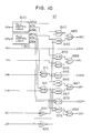
- Fig. 10 shows a block diagram indicating the internal structure of the ALU control circuit 97.
- a main difference from the ALU control circuit 95 shown in Fig. 7 is that instead of the operand conflict detection signal OC indicative of an operand conflict between the preceding and succeeding instructions, instruction decode information LDp indicative of that the preceding instruction is a LOAD instruction is used.
- the instruction decode information LDp indicative of that the preceding instruction is a LOAD instruction, and a write inhibit signal WC for inhibiting a write operation of an operation result by the preceding instruction are sent from the wrap control circuit 92 to the ALU control unit 97.
- the ALU control logic 800 (805) generates OPCp (OPCs) for controlling operation of the ALU, WTp (TWs) indicating a write timing of an operation result and ENDp (ENDs) indicating the end of an arithmetic or logical operation, based on the instruction decode information OPp (OPs) indicating the type of operations of the preceding (succeeding) instruction.
- OPCp OPCp
- WTp WTp
- ENDs indicating the end of an arithmetic or logical operation
- An instruction decode information CHp (CHs) indicative of that the preceding (succeeding) instruction writes an operation result into the general register group 70 is synchonized with the write timing WTp (WTs) at an AND gate 810 (815).
- An output from an inverter 820 indicates that it is not necessary to inhibit a write operation of the operation result by the preceding instruction.
- An output from an inverter 835 indicates that the preceding instruction is not a LOAD instruction.
- an output from an AND gate 845 causes to output an operation control signal for the preceding instruction to the ALU in the case the preceding instruction is not a LOAD instruction.
- an output from an AND gate 846 causes to output an operation control signal for the succeeding instruction to the ALU, in the case the preceding instruction is a LOAD instruction.
- An OR gate 885 outputs the operation control signal OPC selected by the AND gates 845 and 846.
- R1p designating a register of the general register group 70 into which an output OP2pf from a selector 84 is written by the preceding instruction, is directly sent to the general purpose register 70.
- An output of an AND gate 855 designates a register of the general register group 70 into which an operation result of the ALU 82 by the preceding instruction is written, in the case where the preceding instruction is not a LOAD instruction.
- an output of an AND gate 856 designates a register of the general register group 70 into which an operation result of the ALU 82 by the succeeding instruction is written, in the case where the preceding instruction is a LOAD instruction.
- An output from an OR gate 886 designates a register selected by the AND gates 855 and 856 into which an operation result by the ALU 82 is written.
- an AND gate 865 outputs a write enable signal WPp for enabling a write operation of an output OP2p from the selector 84 into the general register group 70 by the preceding instruction. If the preceding instruction is not a LOAD instruction, an output from an AND gate 866 allows the preceding instruction to write an operation result by the ALU 82 into the general register group 70. Also if the preceding instruction is a LOAD instruction, an output from an AND gate 867 allows the succeeding instruction to write an operation result by the ALU 82 into the general register group 70. When one of the AND gates 866 and 867 allows a write operation of an operation result by the ALU 82, an OR gate 887 outputs a write enable signal WP. The write enable signals WPp and WP are sent to the general register group 70.
- An operation end signal EOPp is outputted from an AND gate 875 on the condition that the preceding instruction is a LOAD instruction, the preceding instruction has completed its arithmetic or logical operation by writing an output OP2p from the selector 84 into the general register group 70, and the succeeding instruction has also completed its operation at the ALU 82.
- An output from an AND gate 876 indicates that the preceding instruction has completed its arithmetic or logical operation at the ALU 82 in the case where the preceding instruction is not a LOAD instruction.
- An OR gate 888 outputs an operation end signal EOP when one of the AND gates 875 and 876 indicates the end of an arithmetic or logical operation of the preceding instruction.
- the write enable signal WPp and the operation end signal EOPp are inhibited, to accordingly suspend an operation by the succeeding instruction.
- the operation end signals EOPp and EOP are sent to the out-pointers 38 and 39 to increment them.
- the data processor shown in Fig. 8 can process the series of instructions shown in Fig. 4 in accordance with the timing chart shown in Fig. 5D.
- the preceding instruction is a LOAD instruction and there is an operand conflict between the preceding and succeeding instructions
- the operations for both the preceding and succeeding instructions can be carried out at the same time. Therefore, it is advantageous in that the problem of processing delay to be caused by the operand conflict can be solved, and the processing delay caused by other factors such as a complicated arithmetic or logical operation can be reduced.
Applications Claiming Priority (2)
| Application Number | Priority Date | Filing Date | Title |
|---|---|---|---|
| JP61281720A JPH0810430B2 (ja) | 1986-11-28 | 1986-11-28 | 情報処理装置 |
| JP281720/86 | 1986-11-28 |
Publications (3)
| Publication Number | Publication Date |
|---|---|
| EP0269980A2 true EP0269980A2 (de) | 1988-06-08 |
| EP0269980A3 EP0269980A3 (en) | 1990-04-04 |
| EP0269980B1 EP0269980B1 (de) | 1994-04-13 |
Family
ID=17643043
Family Applications (1)
| Application Number | Title | Priority Date | Filing Date |
|---|---|---|---|
| EP87117331A Expired - Lifetime EP0269980B1 (de) | 1986-11-28 | 1987-11-24 | Datenprozessor zur parallelen Ausführung von miteinander im Konflikt stehenden Befehlen |
Country Status (4)
| Country | Link |
|---|---|
| US (1) | US4928226A (de) |
| EP (1) | EP0269980B1 (de) |
| JP (1) | JPH0810430B2 (de) |
| DE (1) | DE3789604T2 (de) |
Cited By (9)
| Publication number | Priority date | Publication date | Assignee | Title |
|---|---|---|---|---|
| EP0381469A2 (de) * | 1989-02-03 | 1990-08-08 | Digital Equipment Corporation | Verfahren und Datenverarbeitungseinheit zur Pipeline- Verarbeitung von Register- und Registeränderungs- Spezifizierern in dem gleichen Befehl |
| WO1991003784A1 (en) * | 1989-09-11 | 1991-03-21 | Wang Laboratories, Inc. | Improved cpu pipeline having register file bypass on update/access address compare |
| EP0427245A2 (de) * | 1989-11-08 | 1991-05-15 | Hitachi, Ltd. | Datenprozessor mit der Fähigkeit, zwei Befehle gleichzeitig auszuführen |
| FR2654529A1 (fr) * | 1989-11-13 | 1991-05-17 | Mec Corp | Systeme de traitement de l'information capable de contourner un dispositif de memoire pour envoyer des donnees-memoire, en tant qu'operande a l'unite arithmetique et logique. |
| GB2285322A (en) * | 1993-12-28 | 1995-07-05 | Fujitsu Ltd | Processor having multiple instruction registers |
| US5432918A (en) * | 1990-06-29 | 1995-07-11 | Digital Equipment Corporation | Method and apparatus for ordering read and write operations using conflict bits in a write queue |
| US5450555A (en) * | 1990-06-29 | 1995-09-12 | Digital Equipment Corporation | Register logging in pipelined computer using register log queue of register content changes and base queue of register log queue pointers for respective instructions |
| US5471591A (en) * | 1990-06-29 | 1995-11-28 | Digital Equipment Corporation | Combined write-operand queue and read-after-write dependency scoreboard |
| US5488730A (en) * | 1990-06-29 | 1996-01-30 | Digital Equipment Corporation | Register conflict scoreboard in pipelined computer using pipelined reference counts |
Families Citing this family (22)
| Publication number | Priority date | Publication date | Assignee | Title |
|---|---|---|---|---|
| JP2783285B2 (ja) * | 1988-08-10 | 1998-08-06 | 株式会社日立製作所 | 情報処理装置 |
| JP2810068B2 (ja) * | 1988-11-11 | 1998-10-15 | 株式会社日立製作所 | プロセッサシステム、コンピュータシステム及び命令処理方法 |
| US5073855A (en) * | 1989-06-30 | 1991-12-17 | Bull Hn Information Systems Inc. | Resource conflict detection method and apparatus included in a pipelined processing unit |
| US5745723A (en) * | 1989-09-04 | 1998-04-28 | Mitsubishi Denki Kabushiki Kaisha | Data processing system capable of execution of plural instructions in parallel |
| US5615349A (en) * | 1990-09-04 | 1997-03-25 | Mitsubishi Denki Kabushiki Kaisha | Data processing system capable of execution of plural instructions in parallel |
| JPH07120284B2 (ja) * | 1989-09-04 | 1995-12-20 | 三菱電機株式会社 | データ処理装置 |
| US5295249A (en) * | 1990-05-04 | 1994-03-15 | International Business Machines Corporation | Compounding preprocessor for cache for identifying multiple instructions which may be executed in parallel |
| JP2834292B2 (ja) * | 1990-08-15 | 1998-12-09 | 株式会社日立製作所 | データ・プロセッサ |
| JP2642529B2 (ja) * | 1991-04-30 | 1997-08-20 | 株式会社東芝 | 並列プロセッサーの命令分配処理装置 |
| EP0886209B1 (de) | 1991-07-08 | 2005-03-23 | Seiko Epson Corporation | RISC-Prozessor mit erweiterbarer Architektur |
| US5493687A (en) | 1991-07-08 | 1996-02-20 | Seiko Epson Corporation | RISC microprocessor architecture implementing multiple typed register sets |
| US5539911A (en) | 1991-07-08 | 1996-07-23 | Seiko Epson Corporation | High-performance, superscalar-based computer system with out-of-order instruction execution |
| JP2779557B2 (ja) * | 1991-07-09 | 1998-07-23 | 三菱電機株式会社 | 並列演算処理装置 |
| JP2685999B2 (ja) * | 1991-07-15 | 1997-12-08 | 株式会社ピーエフユー | 並列実行方式 |
| US5283874A (en) * | 1991-10-21 | 1994-02-01 | Intel Corporation | Cross coupling mechanisms for simultaneously completing consecutive pipeline instructions even if they begin to process at the same microprocessor of the issue fee |
| EP0544083A3 (en) * | 1991-11-26 | 1994-09-14 | Ibm | Interleaved risc-type parallel processor and processing methods |
| EP0636256B1 (de) | 1992-03-31 | 1997-06-04 | Seiko Epson Corporation | Befehlsablauffolgeplanung von einem risc-superskalarprozessor |
| WO1993022722A1 (en) | 1992-05-01 | 1993-11-11 | Seiko Epson Corporation | A system and method for retiring instructions in a superscalar microprocessor |
| DE69320991T2 (de) | 1992-12-31 | 1999-01-28 | Seiko Epson Corp | System und verfahren zur änderung der namen von registern |
| US5628021A (en) | 1992-12-31 | 1997-05-06 | Seiko Epson Corporation | System and method for assigning tags to control instruction processing in a superscalar processor |
| CA2123442A1 (en) * | 1993-09-20 | 1995-03-21 | David S. Ray | Multiple execution unit dispatch with instruction dependency |
| US20050071830A1 (en) * | 2003-09-30 | 2005-03-31 | Starcore, Llc | Method and system for processing a sequence of instructions |
Citations (2)
| Publication number | Priority date | Publication date | Assignee | Title |
|---|---|---|---|---|
| JPS5646170A (en) | 1979-09-06 | 1981-04-27 | Ross Operating Valve Co | Multiple safety valve |
| JPS58176751A (ja) | 1982-04-09 | 1983-10-17 | Hitachi Ltd | 命令語解読ユニツト |
Family Cites Families (12)
| Publication number | Priority date | Publication date | Assignee | Title |
|---|---|---|---|---|
| JPS5621240A (en) * | 1979-07-27 | 1981-02-27 | Hitachi Ltd | Information processor |
| JPS57155666A (en) * | 1981-03-20 | 1982-09-25 | Fujitsu Ltd | Instruction controlling system of vector processor |
| US4532589A (en) * | 1981-12-02 | 1985-07-30 | Hitachi, Ltd. | Digital data processor with two operation units |
| JPS58176151A (ja) * | 1982-04-06 | 1983-10-15 | 石川島播磨重工業株式会社 | セメント焼成設備のクリンカ品質制御方法 |
| JPS58189738A (ja) * | 1982-04-30 | 1983-11-05 | Hitachi Ltd | デ−タ処理システム |
| JPS58189739A (ja) * | 1982-04-30 | 1983-11-05 | Hitachi Ltd | デ−タ処理システム |
| JPS592143A (ja) * | 1982-06-29 | 1984-01-07 | Hitachi Ltd | 情報処理装置 |
| JPS5932045A (ja) * | 1982-08-16 | 1984-02-21 | Hitachi Ltd | 情報処理装置 |
| JPH063584B2 (ja) * | 1983-12-19 | 1994-01-12 | 株式会社日立製作所 | 情報処理装置 |
| JPH0658631B2 (ja) * | 1983-12-19 | 1994-08-03 | 株式会社日立製作所 | デ−タ処理装置 |
| JPS61160142A (ja) * | 1984-12-29 | 1986-07-19 | Hitachi Ltd | デ−タ処理装置 |
| JPH0762823B2 (ja) * | 1985-05-22 | 1995-07-05 | 株式会社日立製作所 | デ−タ処理装置 |
-
1986
- 1986-11-28 JP JP61281720A patent/JPH0810430B2/ja not_active Expired - Lifetime
-
1987
- 1987-11-24 DE DE3789604T patent/DE3789604T2/de not_active Expired - Fee Related
- 1987-11-24 EP EP87117331A patent/EP0269980B1/de not_active Expired - Lifetime
- 1987-11-24 US US07/124,839 patent/US4928226A/en not_active Expired - Lifetime
Patent Citations (2)
| Publication number | Priority date | Publication date | Assignee | Title |
|---|---|---|---|---|
| JPS5646170A (en) | 1979-09-06 | 1981-04-27 | Ross Operating Valve Co | Multiple safety valve |
| JPS58176751A (ja) | 1982-04-09 | 1983-10-17 | Hitachi Ltd | 命令語解読ユニツト |
Cited By (15)
| Publication number | Priority date | Publication date | Assignee | Title |
|---|---|---|---|---|
| US5167026A (en) * | 1989-02-03 | 1992-11-24 | Digital Equipment Corporation | Simultaneously or sequentially decoding multiple specifiers of a variable length pipeline instruction based on detection of modified value of specifier registers |
| EP0381469A2 (de) * | 1989-02-03 | 1990-08-08 | Digital Equipment Corporation | Verfahren und Datenverarbeitungseinheit zur Pipeline- Verarbeitung von Register- und Registeränderungs- Spezifizierern in dem gleichen Befehl |
| EP0381469A3 (de) * | 1989-02-03 | 1992-09-02 | Digital Equipment Corporation | Verfahren und Datenverarbeitungseinheit zur Pipeline- Verarbeitung von Register- und Registeränderungs- Spezifizierern in dem gleichen Befehl |
| WO1991003784A1 (en) * | 1989-09-11 | 1991-03-21 | Wang Laboratories, Inc. | Improved cpu pipeline having register file bypass on update/access address compare |
| US5123108A (en) * | 1989-09-11 | 1992-06-16 | Wang Laboratories, Inc. | Improved cpu pipeline having register file bypass and working register bypass on update/access address compare |
| EP0427245A2 (de) * | 1989-11-08 | 1991-05-15 | Hitachi, Ltd. | Datenprozessor mit der Fähigkeit, zwei Befehle gleichzeitig auszuführen |
| EP0427245A3 (en) * | 1989-11-08 | 1992-01-29 | Hitachi, Ltd. | Data processor capable of simultaneously executing two instructions |
| FR2654529A1 (fr) * | 1989-11-13 | 1991-05-17 | Mec Corp | Systeme de traitement de l'information capable de contourner un dispositif de memoire pour envoyer des donnees-memoire, en tant qu'operande a l'unite arithmetique et logique. |
| US5432918A (en) * | 1990-06-29 | 1995-07-11 | Digital Equipment Corporation | Method and apparatus for ordering read and write operations using conflict bits in a write queue |
| US5450555A (en) * | 1990-06-29 | 1995-09-12 | Digital Equipment Corporation | Register logging in pipelined computer using register log queue of register content changes and base queue of register log queue pointers for respective instructions |
| US5471591A (en) * | 1990-06-29 | 1995-11-28 | Digital Equipment Corporation | Combined write-operand queue and read-after-write dependency scoreboard |
| US5488730A (en) * | 1990-06-29 | 1996-01-30 | Digital Equipment Corporation | Register conflict scoreboard in pipelined computer using pipelined reference counts |
| GB2285322A (en) * | 1993-12-28 | 1995-07-05 | Fujitsu Ltd | Processor having multiple instruction registers |
| US5649226A (en) * | 1993-12-28 | 1997-07-15 | Fujitsu Limited | Processor having multiple instruction registers |
| GB2285322B (en) * | 1993-12-28 | 1998-10-07 | Fujitsu Ltd | Processor having multiple instruction register |
Also Published As
| Publication number | Publication date |
|---|---|
| EP0269980A3 (en) | 1990-04-04 |
| EP0269980B1 (de) | 1994-04-13 |
| JPH0810430B2 (ja) | 1996-01-31 |
| DE3789604D1 (de) | 1994-05-19 |
| JPS63136138A (ja) | 1988-06-08 |
| US4928226A (en) | 1990-05-22 |
| DE3789604T2 (de) | 1994-07-21 |
Similar Documents
| Publication | Publication Date | Title |
|---|---|---|
| US4928226A (en) | Data processor for parallelly executing conflicting instructions | |
| CA1223371A (en) | System for by-pass control in pipeline operation of computer | |
| EP0207665B1 (de) | Bidirektionale Vorhersage und Optimierung von Verzweigungen | |
| EP0996057B1 (de) | Datenprozessor mit einer Befehlseinheit, die einen Cachespeicher und einen ROM aufweist. | |
| US5341482A (en) | Method for synchronization of arithmetic exceptions in central processing units having pipelined execution units simultaneously executing instructions | |
| JPH07281896A (ja) | 情報処理装置 | |
| JP2003029986A (ja) | プロセッサ間レジスタ継承方法及びその装置 | |
| US5497496A (en) | Superscalar processor controlling fetching of instructions based upon number of empty instructions registers detected for each cycle | |
| EP0094535B1 (de) | Nach dem Prinzip der Pipeline arbeitendes Datenverarbeitungssystem | |
| EP0093430B1 (de) | Nach dem Prinzip der Pipeline arbeitendes Datenverarbeitungssystem | |
| US20030005261A1 (en) | Method and apparatus for attaching accelerator hardware containing internal state to a processing core | |
| EP0742517B1 (de) | Programmübersetzungsgerät und Prozessor, die eine schnelle Ausführung von Unterprogrammsprungbefehlen erreichen | |
| EP0482200B1 (de) | Unterbrechungsverarbeitungssystem | |
| CN115934168A (zh) | 处理器和内存访问方法 | |
| US6092183A (en) | Data processor for processing a complex instruction by dividing it into executing units | |
| US5634136A (en) | Data processor and method of controlling the same | |
| JPH0743648B2 (ja) | 情報処理装置 | |
| EP0496407A2 (de) | Parallelfliessband-Befehlsverarbeitungssystem für sehr lange Befehlswörter | |
| KR100241970B1 (ko) | 파이프라인 처리를 수행하는 데이터 처리 장치 | |
| RU2816094C1 (ru) | Vliw-процессор с дополнительным подготовительным конвейером и предсказателем перехода | |
| JP2814683B2 (ja) | 命令処理装置 | |
| JP2819733B2 (ja) | 情報処理装置 | |
| JP2591325B2 (ja) | 分岐制御装置 | |
| CN113703841A (zh) | 一种寄存器数据读取的优化方法、装置及介质 | |
| JPH01296345A (ja) | 情報処理装置 |
Legal Events
| Date | Code | Title | Description |
|---|---|---|---|
| PUAI | Public reference made under article 153(3) epc to a published international application that has entered the european phase |
Free format text: ORIGINAL CODE: 0009012 |
|
| 17P | Request for examination filed |
Effective date: 19871223 |
|
| AK | Designated contracting states |
Kind code of ref document: A2 Designated state(s): DE FR GB |
|
| PUAL | Search report despatched |
Free format text: ORIGINAL CODE: 0009013 |
|
| AK | Designated contracting states |
Kind code of ref document: A3 Designated state(s): DE FR GB |
|
| 17Q | First examination report despatched |
Effective date: 19920130 |
|
| GRAA | (expected) grant |
Free format text: ORIGINAL CODE: 0009210 |
|
| AK | Designated contracting states |
Kind code of ref document: B1 Designated state(s): DE FR GB |
|
| REF | Corresponds to: |
Ref document number: 3789604 Country of ref document: DE Date of ref document: 19940519 |
|
| ET | Fr: translation filed | ||
| PLBE | No opposition filed within time limit |
Free format text: ORIGINAL CODE: 0009261 |
|
| STAA | Information on the status of an ep patent application or granted ep patent |
Free format text: STATUS: NO OPPOSITION FILED WITHIN TIME LIMIT |
|
| 26N | No opposition filed | ||
| PGFP | Annual fee paid to national office [announced via postgrant information from national office to epo] |
Ref country code: FR Payment date: 20010919 Year of fee payment: 15 |
|
| PGFP | Annual fee paid to national office [announced via postgrant information from national office to epo] |
Ref country code: GB Payment date: 20011116 Year of fee payment: 15 |
|
| REG | Reference to a national code |
Ref country code: GB Ref legal event code: IF02 |
|
| PGFP | Annual fee paid to national office [announced via postgrant information from national office to epo] |
Ref country code: DE Payment date: 20020129 Year of fee payment: 15 |
|
| PG25 | Lapsed in a contracting state [announced via postgrant information from national office to epo] |
Ref country code: GB Free format text: LAPSE BECAUSE OF NON-PAYMENT OF DUE FEES Effective date: 20021124 |
|
| PG25 | Lapsed in a contracting state [announced via postgrant information from national office to epo] |
Ref country code: DE Free format text: LAPSE BECAUSE OF NON-PAYMENT OF DUE FEES Effective date: 20030603 |
|
| GBPC | Gb: european patent ceased through non-payment of renewal fee | ||
| PG25 | Lapsed in a contracting state [announced via postgrant information from national office to epo] |
Ref country code: FR Free format text: LAPSE BECAUSE OF NON-PAYMENT OF DUE FEES Effective date: 20030731 |
|
| REG | Reference to a national code |
Ref country code: FR Ref legal event code: ST |