EP0267486A2 - Dispositif pour diriger un courant d'air - Google Patents
Dispositif pour diriger un courant d'air Download PDFInfo
- Publication number
- EP0267486A2 EP0267486A2 EP87115721A EP87115721A EP0267486A2 EP 0267486 A2 EP0267486 A2 EP 0267486A2 EP 87115721 A EP87115721 A EP 87115721A EP 87115721 A EP87115721 A EP 87115721A EP 0267486 A2 EP0267486 A2 EP 0267486A2
- Authority
- EP
- European Patent Office
- Prior art keywords
- air
- lamellae
- slats
- fins
- pair
- Prior art date
- Legal status (The legal status is an assumption and is not a legal conclusion. Google has not performed a legal analysis and makes no representation as to the accuracy of the status listed.)
- Granted
Links
Images


Classifications
-
- F—MECHANICAL ENGINEERING; LIGHTING; HEATING; WEAPONS; BLASTING
- F24—HEATING; RANGES; VENTILATING
- F24F—AIR-CONDITIONING; AIR-HUMIDIFICATION; VENTILATION; USE OF AIR CURRENTS FOR SCREENING
- F24F13/00—Details common to, or for air-conditioning, air-humidification, ventilation or use of air currents for screening
- F24F13/26—Arrangements for air-circulation by means of induction, e.g. by fluid coupling or thermal effect
-
- F—MECHANICAL ENGINEERING; LIGHTING; HEATING; WEAPONS; BLASTING
- F24—HEATING; RANGES; VENTILATING
- F24F—AIR-CONDITIONING; AIR-HUMIDIFICATION; VENTILATION; USE OF AIR CURRENTS FOR SCREENING
- F24F13/00—Details common to, or for air-conditioning, air-humidification, ventilation or use of air currents for screening
- F24F13/02—Ducting arrangements
- F24F13/06—Outlets for directing or distributing air into rooms or spaces, e.g. ceiling air diffuser
- F24F13/072—Outlets for directing or distributing air into rooms or spaces, e.g. ceiling air diffuser of elongated shape, e.g. between ceiling panels
-
- F—MECHANICAL ENGINEERING; LIGHTING; HEATING; WEAPONS; BLASTING
- F24—HEATING; RANGES; VENTILATING
- F24F—AIR-CONDITIONING; AIR-HUMIDIFICATION; VENTILATION; USE OF AIR CURRENTS FOR SCREENING
- F24F13/00—Details common to, or for air-conditioning, air-humidification, ventilation or use of air currents for screening
- F24F13/08—Air-flow control members, e.g. louvres, grilles, flaps or guide plates
- F24F13/10—Air-flow control members, e.g. louvres, grilles, flaps or guide plates movable, e.g. dampers
- F24F13/14—Air-flow control members, e.g. louvres, grilles, flaps or guide plates movable, e.g. dampers built up of tilting members, e.g. louvre
- F24F13/1413—Air-flow control members, e.g. louvres, grilles, flaps or guide plates movable, e.g. dampers built up of tilting members, e.g. louvre using more than one tilting member, e.g. with several pivoting blades
Definitions
- the invention relates to a device for guiding an air flow through lamellae which are arranged at the outlet of an air flow-guiding, in particular generating device, two lamellae with their lateral longitudinal edges facing the airflow source being pivoted to one axis or two axially close axes to form a pair of slats, the width of which can be changed by pivoting the slats.
- V-shaped lamellae are known from the outlet of a device guiding an air flow from US Pat. No. 2,224,312.
- the individual adjustment of the slats means that the air flows emerging between the slat pairs are different in strength and direction from one another. In particular, this is intended to achieve a uniform air flow when an air flow is branched off.
- the object of the invention is to improve an air guiding device of the type mentioned in such a way that the depth of penetration into the room can be changed easily and precisely.
- the slats are adjustable by pivoting that the air channels have a smaller width in a direction of flow in and after the air channels in the direction of the incoming air than in an oblique direction to the incoming air.
- the lamellae or profiles form the smallest free flow cross sections between them, as a result of which very high air flow velocities are achieved in the channels, so that the exiting air reaches a great depth of penetration.
- the profiles are arranged so obliquely to one another that the air channels located between them deviate from the incoming direction, the profiles form larger free ones between them Flow cross-sections that lead to a wider distribution of the air flowing out in the room.
- the former setting is particularly advantageous in the case of air outlets arranged on the ceiling of rooms, the air flowing vertically downwards and the second arrangement being particularly advantageous in the case of outlets arranged on the walls of rooms.
- the slats are adjustable by means of a linkage.
- every second lamella can be articulated on a first rod at right angles to the incoming air and the remaining lamellae on a second rod.
- any fraction, preferably one half, of the pairs of plates lying next to one another can be adjusted independently of the plate pairs of the other group.
- the slats are coupled to one another in such a way that when one slat half is moved outwards, the other slat half is adjusted in the opposite direction outwards.
- Air outlet speed and mixing with the room air are further improved in that the lateral end faces of the intermediate space of each pair of fins are open in order to allow secondary air to enter.
- the pairs of lamellae are fastened in front of the outlet so that secondary air can enter the intermediate spaces freely.
- the axes of a number, in particular one half, of the slats lie in a plane which is at an angle ⁇ to the plane of the other axes.
- the angle ⁇ can be 30 to 120 °, in particular approximately 90 °.
- the lamellae are articulated on the sides of a truncated pyramid.
- the axes of the lamellae lie in a cylindrical surface.
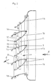
- the device has a plurality of fins 1a, 1b, which can also be called flat profiles, flaps, baffles, blind profiles and two of which 1a, 1b each form a pair of fins 2.
- the lamellae 1a, 1b are articulated at one end to an axis 3.
- This axis 3 is on the the air flow source facing side of the pair of plates, so that the incoming air 4 first hits the axis 3 and then reaches air channels 5, which are each formed between the pair of plates 2.
- the mutually adjacent lamellae 1a, 1b of two different pairs of lamellae each form an air channel between them, which tapers towards the outside in the flow direction 6.
- the axis of rotation is provided with a radius in the direction of flow, which ensures an aerodynamically favorable flow to the air channels.
- the lamellae 1a, 1b which can be rotated about the axis 3, can be adjusted such that the space 7 between two lamellae of a pair of lamellae 2 becomes smaller and the air duct 5 becomes larger and the space larger and the air duct 5 correspondingly smaller.
- the position shown in Figure 1 shows a minimum width B of the air channels 5, so that the air emerging thereby reaches a very high speed and thus a large depth of space.
- the outflow direction 8 is the same or parallel to the inflow direction 6.
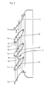
- the slats 1a are not adjusted by the same angle of rotation as the slats 1b, but one of the two slat types 1a or 1b is rotated more than the other, so that the oblique central position shown in FIG. 2 is reached becomes. Because of the larger width B, the outflow velocity is lower than in FIG. 1, so that the lower outlet velocities of the supply air result in a lower penetration depth. If the slats are pivoted even more in an inclined position, with the slats 1a being rotated more downward counterclockwise than the slats 1b, the position shown in FIG. 3 is generated, in which the largest free flow cross-section (B maximum) and a maximum inclination and thus outflow deflection is created. The penetration depth achieved is relatively small but the air deflection is relatively large.
- At least one lamella 1a is connected to a lamella 1b via an inclined articulated rod 13, this articulated rod 13 being inclined to the incoming air and to the rods 10, 11.
- the articulation point 14 of the rod 13 on the lamella 1b is thus at a different distance A1 than the distance A2 between the articulation point 15 of the rod 13 on the lamella 1a and the axis 3.
- the joints and articulation points can be formed by screw channels 16, which are formed on the inside of the lamellae.
- the outer surfaces of the lamellae 1a, 1b are convex, so that the air channels operate in a nozzle-like manner.
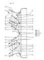
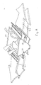
- the exemplary embodiment according to FIGS. 4 to 6 differs from that according to FIGS. 1 to 3 in that part 2a of the slats can be pivoted to one side and the other part 2b of the slats to the other side, so that the inflowing air flow is divided.
- Such a division of the air flow on two opposite sides is particularly advantageous if the air outlet is on the ceiling of a room or hall.
- the linkage is divided into two pairs of rods 10, 11, of which one pair of rods controls a lamella part 2a and the other pair of rods controls the second lamella part 2b.
- actuating rods are articulated on the rods so that when the slats of one part 2a or half are pivoted, the other part 2b or the other half is pivoted in the opposite direction of rotation.
- the lamellae 1a, 1b of a single pair of lamellae 2 form between them the intermediate space 7 which is open towards the end faces in order to allow secondary air to enter. This secondary air then flows out in the outflow direction 8, since it is carried along by the air flowing through the air channels 5.
- the fins are arranged so far in front of the outlet of a device or an air duct that the end faces are free.
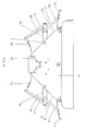
- one half of the lamellae and thus four lamellae 1a, 1b are fastened to the edge of a first outlet opening 17 which is inclined at 45 ° to the inlet opening 19, the second outlet opening 18 being at an angle of 90 ° to the first outlet opening 17 and forms an angle of 45 ° to the inlet opening 19.
- the three openings 17, 18, 19 thus form a straight prism with a right-angled and isosceles triangle as the base.
- four outlet openings can also be provided, which form a truncated pyramid, the base of which is the Forms inlet opening.
- the upper surface of the stump parallel to the inlet opening can form a further outlet opening.
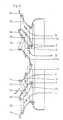
- FIGS. 9 and 10 differs from that according to FIGS. 7 and 8 essentially in that the rods 10, 11, 13 connecting the slats 1a, 13 are shown and between the innermost and therefore the lowest two slats in the interior of the housing an air baffle 23 bent at a right angle is arranged, which prevents an air flow between these two fins.
Priority Applications (1)
| Application Number | Priority Date | Filing Date | Title |
|---|---|---|---|
| AT87115721T ATE57251T1 (de) | 1986-11-12 | 1987-10-27 | Vorrichtung zum leiten eines luftstroms. |
Applications Claiming Priority (2)
| Application Number | Priority Date | Filing Date | Title |
|---|---|---|---|
| DE3638614 | 1986-11-12 | ||
| DE19863638614 DE3638614A1 (de) | 1986-11-12 | 1986-11-12 | Vorrichtung zum leiten eines luftstroms |
Publications (3)
| Publication Number | Publication Date |
|---|---|
| EP0267486A2 true EP0267486A2 (fr) | 1988-05-18 |
| EP0267486A3 EP0267486A3 (en) | 1989-03-15 |
| EP0267486B1 EP0267486B1 (fr) | 1990-10-03 |
Family
ID=6313759
Family Applications (1)
| Application Number | Title | Priority Date | Filing Date |
|---|---|---|---|
| EP87115721A Expired - Lifetime EP0267486B1 (fr) | 1986-11-12 | 1987-10-27 | Dispositif pour diriger un courant d'air |
Country Status (6)
| Country | Link |
|---|---|
| EP (1) | EP0267486B1 (fr) |
| AT (1) | ATE57251T1 (fr) |
| DD (1) | DD262892A5 (fr) |
| DE (2) | DE3638614A1 (fr) |
| ES (1) | ES2018230B3 (fr) |
| GR (1) | GR3001241T3 (fr) |
Cited By (6)
| Publication number | Priority date | Publication date | Assignee | Title |
|---|---|---|---|---|
| DE3914241A1 (de) * | 1989-04-29 | 1990-10-31 | Happel Gmbh & Co | Vorrichtung zum leiten eines luftstromes |
| EP0699876A2 (fr) | 1994-09-02 | 1996-03-06 | TTL Tür + Torluftschleier Lufttechnische Geräte GmbH | Sortie d'air |
| AT400896B (de) * | 1992-06-17 | 1996-04-25 | Troges Gmbh | Drehbare lamelle |
| AT407297B (de) * | 1992-03-19 | 2001-02-26 | Kubag Consulting Ag | Regelklappe |
| CN104764182A (zh) * | 2015-02-13 | 2015-07-08 | 广东美的制冷设备有限公司 | 百叶机构及具有其的出风装置 |
| US20220333798A1 (en) * | 2015-03-05 | 2022-10-20 | Vornado Air, Llc | Air Circulator with Vein Control System |
Families Citing this family (4)
| Publication number | Priority date | Publication date | Assignee | Title |
|---|---|---|---|---|
| JPH068517Y2 (ja) * | 1989-03-10 | 1994-03-02 | トヨタ自動車株式会社 | 変動風発生装置 |
| DE4133734A1 (de) * | 1991-10-11 | 1993-04-22 | Gea Happel Klimatechnik | Luftheiz- und/oder kuehlgeraet |
| DE4305928C2 (de) * | 1993-02-26 | 1997-09-11 | Rahmer & Jansen Gmbh | Vorrichtung und Verfahren zum Kühlen von flüssigen und gasförmigen Medien mittels Luft |
| FR2729461B1 (fr) * | 1995-01-17 | 1997-04-18 | Cerga | Dispositif de reglage de la section de passage d'une bouche de ventilation d'air d'un local |
Citations (1)
| Publication number | Priority date | Publication date | Assignee | Title |
|---|---|---|---|---|
| US2224312A (en) * | 1935-01-17 | 1940-12-10 | Preferred Utilities Company In | Permanent outlet control device |
Family Cites Families (1)
| Publication number | Priority date | Publication date | Assignee | Title |
|---|---|---|---|---|
| US2799989A (en) * | 1954-09-24 | 1957-07-23 | Peter G Kappus | Variable area jet nozzle |
-
1986
- 1986-11-12 DE DE19863638614 patent/DE3638614A1/de not_active Withdrawn
-
1987
- 1987-10-27 DE DE8787115721T patent/DE3765388D1/de not_active Expired - Fee Related
- 1987-10-27 ES ES87115721T patent/ES2018230B3/es not_active Expired - Lifetime
- 1987-10-27 AT AT87115721T patent/ATE57251T1/de not_active IP Right Cessation
- 1987-10-27 EP EP87115721A patent/EP0267486B1/fr not_active Expired - Lifetime
- 1987-11-10 DD DD87308886A patent/DD262892A5/de not_active IP Right Cessation
-
1990
- 1990-12-27 GR GR90400838T patent/GR3001241T3/el unknown
Patent Citations (1)
| Publication number | Priority date | Publication date | Assignee | Title |
|---|---|---|---|---|
| US2224312A (en) * | 1935-01-17 | 1940-12-10 | Preferred Utilities Company In | Permanent outlet control device |
Cited By (11)
| Publication number | Priority date | Publication date | Assignee | Title |
|---|---|---|---|---|
| DE3914241A1 (de) * | 1989-04-29 | 1990-10-31 | Happel Gmbh & Co | Vorrichtung zum leiten eines luftstromes |
| EP0395870A2 (fr) * | 1989-04-29 | 1990-11-07 | GEA Happel Klimatechnik GmbH | Dispositif pour diriger un courant d'air |
| EP0395870A3 (fr) * | 1989-04-29 | 1991-12-27 | GEA Happel Klimatechnik GmbH | Dispositif pour diriger un courant d'air |
| AT407297B (de) * | 1992-03-19 | 2001-02-26 | Kubag Consulting Ag | Regelklappe |
| AT400896B (de) * | 1992-06-17 | 1996-04-25 | Troges Gmbh | Drehbare lamelle |
| EP0699876A2 (fr) | 1994-09-02 | 1996-03-06 | TTL Tür + Torluftschleier Lufttechnische Geräte GmbH | Sortie d'air |
| EP0699876A3 (fr) * | 1994-09-02 | 1997-06-11 | Ttl Tuer & Torluftschleier Luf | Sortie d'air |
| CN104764182A (zh) * | 2015-02-13 | 2015-07-08 | 广东美的制冷设备有限公司 | 百叶机构及具有其的出风装置 |
| CN104764182B (zh) * | 2015-02-13 | 2018-05-01 | 广东美的制冷设备有限公司 | 百叶机构及具有其的出风装置 |
| US20220333798A1 (en) * | 2015-03-05 | 2022-10-20 | Vornado Air, Llc | Air Circulator with Vein Control System |
| US11519616B2 (en) * | 2015-03-05 | 2022-12-06 | Vornado Air, Llc | Air circulator with vane control system |
Also Published As
| Publication number | Publication date |
|---|---|
| EP0267486A3 (en) | 1989-03-15 |
| ES2018230B3 (es) | 1991-04-01 |
| DD262892A5 (de) | 1988-12-14 |
| DE3765388D1 (de) | 1990-11-08 |
| ATE57251T1 (de) | 1990-10-15 |
| DE3638614A1 (de) | 1988-05-26 |
| EP0267486B1 (fr) | 1990-10-03 |
| GR3001241T3 (en) | 1992-07-30 |
Similar Documents
| Publication | Publication Date | Title |
|---|---|---|
| DE10157408B4 (de) | Zuluftvorrichtung | |
| WO2015062890A1 (fr) | Diffuseur d'air | |
| WO2019020489A1 (fr) | Buse de sortie d'un véhicule automobile | |
| DE3437259C2 (fr) | ||
| DE69529913T2 (de) | Luftleitblech | |
| EP0267486B1 (fr) | Dispositif pour diriger un courant d'air | |
| DE2556538B2 (de) | Anordnung zum Belüften und/oder Temperieren eines Raumes | |
| EP0335151B1 (fr) | Sortie d'air pour créer un courant d'air de déplacement à faible turbulence | |
| EP0267485B1 (fr) | Dispositif pour diriger un courant d'air | |
| EP0361213A1 (fr) | Diffuseur d'air pour espaces intérieurs, notamment pour l'intérieur d'un véhicule automobile | |
| EP0360147B1 (fr) | Boucle à écoulement en spirales | |
| EP0149752B1 (fr) | Echappement d'air de forme rectangulaire pour un dispositif de climatisation | |
| DE102009020574B3 (de) | Luftauslassdüse | |
| DE2033195B2 (de) | Luftaustrittseinrichtung für Klimaanlagen | |
| DE202021104865U1 (de) | Fahrzeugbelüfter, umfassend magnetisch ausrichtbare Ablenkelemente | |
| EP0667496B1 (fr) | Carter pour ventilation d'air | |
| DE2525977C2 (de) | Lüftungsgitter für die Belüftung von Innenräumen | |
| DE3231486C2 (fr) | ||
| DE2105718C3 (de) | Schlitzlüfter für den Einbau in Gebäudedecken | |
| DE2810383C2 (de) | Ausblaseeinheit mit Regulierung bzw. Verschiebung der auszublasenden Luftmenge | |
| EP0239854B1 (fr) | Sortie d'air | |
| EP4224077A1 (fr) | Passage d'air | |
| DE7500088U (de) | Schlitzauslass zur luftfuehrung bei lufttechnischen geraeten u.dgl. | |
| DE2830363B1 (de) | Ausblaseeinheit | |
| DE1105587B (de) | Luftkanal fuer Lueftungsanlagen |
Legal Events
| Date | Code | Title | Description |
|---|---|---|---|
| PUAI | Public reference made under article 153(3) epc to a published international application that has entered the european phase |
Free format text: ORIGINAL CODE: 0009012 |
|
| AK | Designated contracting states |
Kind code of ref document: A2 Designated state(s): AT BE CH DE ES FR GB GR IT LI NL SE |
|
| PUAL | Search report despatched |
Free format text: ORIGINAL CODE: 0009013 |
|
| AK | Designated contracting states |
Kind code of ref document: A3 Designated state(s): AT BE CH DE ES FR GB GR IT LI NL SE |
|
| 17P | Request for examination filed |
Effective date: 19890225 |
|
| 17Q | First examination report despatched |
Effective date: 19890629 |
|
| GRAA | (expected) grant |
Free format text: ORIGINAL CODE: 0009210 |
|
| AK | Designated contracting states |
Kind code of ref document: B1 Designated state(s): AT BE CH DE ES FR GB GR IT LI NL SE |
|
| REF | Corresponds to: |
Ref document number: 57251 Country of ref document: AT Date of ref document: 19901015 Kind code of ref document: T |
|
| GBT | Gb: translation of ep patent filed (gb section 77(6)(a)/1977) | ||
| REF | Corresponds to: |
Ref document number: 3765388 Country of ref document: DE Date of ref document: 19901108 |
|
| ET | Fr: translation filed | ||
| ITF | It: translation for a ep patent filed |
Owner name: SOCIETA' ITALIANA BREVETTI S.P.A. |
|
| PLBE | No opposition filed within time limit |
Free format text: ORIGINAL CODE: 0009261 |
|
| STAA | Information on the status of an ep patent application or granted ep patent |
Free format text: STATUS: NO OPPOSITION FILED WITHIN TIME LIMIT |
|
| 26N | No opposition filed | ||
| ITTA | It: last paid annual fee | ||
| REG | Reference to a national code |
Ref country code: GR Ref legal event code: FG4A Free format text: 3001241 |
|
| EAL | Se: european patent in force in sweden |
Ref document number: 87115721.0 |
|
| REG | Reference to a national code |
Ref country code: GB Ref legal event code: IF02 |
|
| PGFP | Annual fee paid to national office [announced via postgrant information from national office to epo] |
Ref country code: GR Payment date: 20040924 Year of fee payment: 18 |
|
| PGFP | Annual fee paid to national office [announced via postgrant information from national office to epo] |
Ref country code: NL Payment date: 20041003 Year of fee payment: 18 |
|
| PGFP | Annual fee paid to national office [announced via postgrant information from national office to epo] |
Ref country code: SE Payment date: 20041006 Year of fee payment: 18 |
|
| PGFP | Annual fee paid to national office [announced via postgrant information from national office to epo] |
Ref country code: FR Payment date: 20041008 Year of fee payment: 18 |
|
| PGFP | Annual fee paid to national office [announced via postgrant information from national office to epo] |
Ref country code: AT Payment date: 20041013 Year of fee payment: 18 |
|
| PGFP | Annual fee paid to national office [announced via postgrant information from national office to epo] |
Ref country code: DE Payment date: 20041021 Year of fee payment: 18 |
|
| PGFP | Annual fee paid to national office [announced via postgrant information from national office to epo] |
Ref country code: CH Payment date: 20041027 Year of fee payment: 18 Ref country code: GB Payment date: 20041027 Year of fee payment: 18 |
|
| PGFP | Annual fee paid to national office [announced via postgrant information from national office to epo] |
Ref country code: ES Payment date: 20041116 Year of fee payment: 18 |
|
| PGFP | Annual fee paid to national office [announced via postgrant information from national office to epo] |
Ref country code: BE Payment date: 20041215 Year of fee payment: 18 |
|
| PG25 | Lapsed in a contracting state [announced via postgrant information from national office to epo] |
Ref country code: IT Free format text: LAPSE BECAUSE OF NON-PAYMENT OF DUE FEES Effective date: 20051027 Ref country code: AT Free format text: LAPSE BECAUSE OF NON-PAYMENT OF DUE FEES Effective date: 20051027 |
|
| PG25 | Lapsed in a contracting state [announced via postgrant information from national office to epo] |
Ref country code: SE Free format text: LAPSE BECAUSE OF NON-PAYMENT OF DUE FEES Effective date: 20051028 Ref country code: ES Free format text: LAPSE BECAUSE OF NON-PAYMENT OF DUE FEES Effective date: 20051028 |
|
| PG25 | Lapsed in a contracting state [announced via postgrant information from national office to epo] |
Ref country code: CH Free format text: LAPSE BECAUSE OF NON-PAYMENT OF DUE FEES Effective date: 20051031 Ref country code: BE Free format text: LAPSE BECAUSE OF NON-PAYMENT OF DUE FEES Effective date: 20051031 Ref country code: LI Free format text: LAPSE BECAUSE OF NON-PAYMENT OF DUE FEES Effective date: 20051031 |
|
| PG25 | Lapsed in a contracting state [announced via postgrant information from national office to epo] |
Ref country code: NL Free format text: LAPSE BECAUSE OF NON-PAYMENT OF DUE FEES Effective date: 20060501 |
|
| PG25 | Lapsed in a contracting state [announced via postgrant information from national office to epo] |
Ref country code: DE Free format text: LAPSE BECAUSE OF NON-PAYMENT OF DUE FEES Effective date: 20060503 |
|
| REG | Reference to a national code |
Ref country code: CH Ref legal event code: PL |
|
| EUG | Se: european patent has lapsed | ||
| GBPC | Gb: european patent ceased through non-payment of renewal fee |
Effective date: 20051027 |
|
| PG25 | Lapsed in a contracting state [announced via postgrant information from national office to epo] |
Ref country code: FR Free format text: LAPSE BECAUSE OF NON-PAYMENT OF DUE FEES Effective date: 20060630 |
|
| NLV4 | Nl: lapsed or anulled due to non-payment of the annual fee |
Effective date: 20060501 |
|
| REG | Reference to a national code |
Ref country code: FR Ref legal event code: ST Effective date: 20060630 |
|
| REG | Reference to a national code |
Ref country code: ES Ref legal event code: FD2A Effective date: 20051028 |
|
| BERE | Be: lapsed |
Owner name: *HAPPEL G.M.B.H. & CO. Effective date: 20051031 |
|
| PG25 | Lapsed in a contracting state [announced via postgrant information from national office to epo] |
Ref country code: GR Free format text: LAPSE BECAUSE OF NON-PAYMENT OF DUE FEES Effective date: 19901003 |