EP0267486A2 - Device for guiding an air stream - Google Patents
Device for guiding an air stream Download PDFInfo
- Publication number
- EP0267486A2 EP0267486A2 EP87115721A EP87115721A EP0267486A2 EP 0267486 A2 EP0267486 A2 EP 0267486A2 EP 87115721 A EP87115721 A EP 87115721A EP 87115721 A EP87115721 A EP 87115721A EP 0267486 A2 EP0267486 A2 EP 0267486A2
- Authority
- EP
- European Patent Office
- Prior art keywords
- air
- lamellae
- slats
- fins
- pair
- Prior art date
- Legal status (The legal status is an assumption and is not a legal conclusion. Google has not performed a legal analysis and makes no representation as to the accuracy of the status listed.)
- Granted
Links
Images


Classifications
-
- F—MECHANICAL ENGINEERING; LIGHTING; HEATING; WEAPONS; BLASTING
- F24—HEATING; RANGES; VENTILATING
- F24F—AIR-CONDITIONING; AIR-HUMIDIFICATION; VENTILATION; USE OF AIR CURRENTS FOR SCREENING
- F24F13/00—Details common to, or for air-conditioning, air-humidification, ventilation or use of air currents for screening
- F24F13/26—Arrangements for air-circulation by means of induction, e.g. by fluid coupling or thermal effect
-
- F—MECHANICAL ENGINEERING; LIGHTING; HEATING; WEAPONS; BLASTING
- F24—HEATING; RANGES; VENTILATING
- F24F—AIR-CONDITIONING; AIR-HUMIDIFICATION; VENTILATION; USE OF AIR CURRENTS FOR SCREENING
- F24F13/00—Details common to, or for air-conditioning, air-humidification, ventilation or use of air currents for screening
- F24F13/02—Ducting arrangements
- F24F13/06—Outlets for directing or distributing air into rooms or spaces, e.g. ceiling air diffuser
- F24F13/072—Outlets for directing or distributing air into rooms or spaces, e.g. ceiling air diffuser of elongated shape, e.g. between ceiling panels
-
- F—MECHANICAL ENGINEERING; LIGHTING; HEATING; WEAPONS; BLASTING
- F24—HEATING; RANGES; VENTILATING
- F24F—AIR-CONDITIONING; AIR-HUMIDIFICATION; VENTILATION; USE OF AIR CURRENTS FOR SCREENING
- F24F13/00—Details common to, or for air-conditioning, air-humidification, ventilation or use of air currents for screening
- F24F13/08—Air-flow control members, e.g. louvres, grilles, flaps or guide plates
- F24F13/10—Air-flow control members, e.g. louvres, grilles, flaps or guide plates movable, e.g. dampers
- F24F13/14—Air-flow control members, e.g. louvres, grilles, flaps or guide plates movable, e.g. dampers built up of tilting members, e.g. louvre
- F24F13/1413—Air-flow control members, e.g. louvres, grilles, flaps or guide plates movable, e.g. dampers built up of tilting members, e.g. louvre using more than one tilting member, e.g. with several pivoting blades
Definitions
- the invention relates to a device for guiding an air flow through lamellae which are arranged at the outlet of an air flow-guiding, in particular generating device, two lamellae with their lateral longitudinal edges facing the airflow source being pivoted to one axis or two axially close axes to form a pair of slats, the width of which can be changed by pivoting the slats.
- V-shaped lamellae are known from the outlet of a device guiding an air flow from US Pat. No. 2,224,312.
- the individual adjustment of the slats means that the air flows emerging between the slat pairs are different in strength and direction from one another. In particular, this is intended to achieve a uniform air flow when an air flow is branched off.
- the object of the invention is to improve an air guiding device of the type mentioned in such a way that the depth of penetration into the room can be changed easily and precisely.
- the slats are adjustable by pivoting that the air channels have a smaller width in a direction of flow in and after the air channels in the direction of the incoming air than in an oblique direction to the incoming air.
- the lamellae or profiles form the smallest free flow cross sections between them, as a result of which very high air flow velocities are achieved in the channels, so that the exiting air reaches a great depth of penetration.
- the profiles are arranged so obliquely to one another that the air channels located between them deviate from the incoming direction, the profiles form larger free ones between them Flow cross-sections that lead to a wider distribution of the air flowing out in the room.
- the former setting is particularly advantageous in the case of air outlets arranged on the ceiling of rooms, the air flowing vertically downwards and the second arrangement being particularly advantageous in the case of outlets arranged on the walls of rooms.
- the slats are adjustable by means of a linkage.
- every second lamella can be articulated on a first rod at right angles to the incoming air and the remaining lamellae on a second rod.
- any fraction, preferably one half, of the pairs of plates lying next to one another can be adjusted independently of the plate pairs of the other group.
- the slats are coupled to one another in such a way that when one slat half is moved outwards, the other slat half is adjusted in the opposite direction outwards.
- Air outlet speed and mixing with the room air are further improved in that the lateral end faces of the intermediate space of each pair of fins are open in order to allow secondary air to enter.
- the pairs of lamellae are fastened in front of the outlet so that secondary air can enter the intermediate spaces freely.
- the axes of a number, in particular one half, of the slats lie in a plane which is at an angle ⁇ to the plane of the other axes.
- the angle ⁇ can be 30 to 120 °, in particular approximately 90 °.
- the lamellae are articulated on the sides of a truncated pyramid.
- the axes of the lamellae lie in a cylindrical surface.
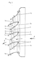
- the device has a plurality of fins 1a, 1b, which can also be called flat profiles, flaps, baffles, blind profiles and two of which 1a, 1b each form a pair of fins 2.
- the lamellae 1a, 1b are articulated at one end to an axis 3.
- This axis 3 is on the the air flow source facing side of the pair of plates, so that the incoming air 4 first hits the axis 3 and then reaches air channels 5, which are each formed between the pair of plates 2.
- the mutually adjacent lamellae 1a, 1b of two different pairs of lamellae each form an air channel between them, which tapers towards the outside in the flow direction 6.
- the axis of rotation is provided with a radius in the direction of flow, which ensures an aerodynamically favorable flow to the air channels.
- the lamellae 1a, 1b which can be rotated about the axis 3, can be adjusted such that the space 7 between two lamellae of a pair of lamellae 2 becomes smaller and the air duct 5 becomes larger and the space larger and the air duct 5 correspondingly smaller.
- the position shown in Figure 1 shows a minimum width B of the air channels 5, so that the air emerging thereby reaches a very high speed and thus a large depth of space.
- the outflow direction 8 is the same or parallel to the inflow direction 6.
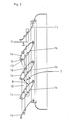
- the slats 1a are not adjusted by the same angle of rotation as the slats 1b, but one of the two slat types 1a or 1b is rotated more than the other, so that the oblique central position shown in FIG. 2 is reached becomes. Because of the larger width B, the outflow velocity is lower than in FIG. 1, so that the lower outlet velocities of the supply air result in a lower penetration depth. If the slats are pivoted even more in an inclined position, with the slats 1a being rotated more downward counterclockwise than the slats 1b, the position shown in FIG. 3 is generated, in which the largest free flow cross-section (B maximum) and a maximum inclination and thus outflow deflection is created. The penetration depth achieved is relatively small but the air deflection is relatively large.
- At least one lamella 1a is connected to a lamella 1b via an inclined articulated rod 13, this articulated rod 13 being inclined to the incoming air and to the rods 10, 11.
- the articulation point 14 of the rod 13 on the lamella 1b is thus at a different distance A1 than the distance A2 between the articulation point 15 of the rod 13 on the lamella 1a and the axis 3.
- the joints and articulation points can be formed by screw channels 16, which are formed on the inside of the lamellae.
- the outer surfaces of the lamellae 1a, 1b are convex, so that the air channels operate in a nozzle-like manner.
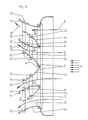
- the exemplary embodiment according to FIGS. 4 to 6 differs from that according to FIGS. 1 to 3 in that part 2a of the slats can be pivoted to one side and the other part 2b of the slats to the other side, so that the inflowing air flow is divided.
- Such a division of the air flow on two opposite sides is particularly advantageous if the air outlet is on the ceiling of a room or hall.
- the linkage is divided into two pairs of rods 10, 11, of which one pair of rods controls a lamella part 2a and the other pair of rods controls the second lamella part 2b.
- actuating rods are articulated on the rods so that when the slats of one part 2a or half are pivoted, the other part 2b or the other half is pivoted in the opposite direction of rotation.
- the lamellae 1a, 1b of a single pair of lamellae 2 form between them the intermediate space 7 which is open towards the end faces in order to allow secondary air to enter. This secondary air then flows out in the outflow direction 8, since it is carried along by the air flowing through the air channels 5.
- the fins are arranged so far in front of the outlet of a device or an air duct that the end faces are free.
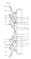
- one half of the lamellae and thus four lamellae 1a, 1b are fastened to the edge of a first outlet opening 17 which is inclined at 45 ° to the inlet opening 19, the second outlet opening 18 being at an angle of 90 ° to the first outlet opening 17 and forms an angle of 45 ° to the inlet opening 19.
- the three openings 17, 18, 19 thus form a straight prism with a right-angled and isosceles triangle as the base.
- four outlet openings can also be provided, which form a truncated pyramid, the base of which is the Forms inlet opening.
- the upper surface of the stump parallel to the inlet opening can form a further outlet opening.
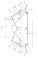
- FIGS. 9 and 10 differs from that according to FIGS. 7 and 8 essentially in that the rods 10, 11, 13 connecting the slats 1a, 13 are shown and between the innermost and therefore the lowest two slats in the interior of the housing an air baffle 23 bent at a right angle is arranged, which prevents an air flow between these two fins.
Landscapes
- Engineering & Computer Science (AREA)
- Chemical & Material Sciences (AREA)
- Combustion & Propulsion (AREA)
- Mechanical Engineering (AREA)
- General Engineering & Computer Science (AREA)
- Air-Flow Control Members (AREA)
- Duct Arrangements (AREA)
- Electrical Discharge Machining, Electrochemical Machining, And Combined Machining (AREA)
- Regulation And Control Of Combustion (AREA)
- Looms (AREA)
- Braking Arrangements (AREA)
- Gas-Insulated Switchgears (AREA)
- Supplying Of Containers To The Packaging Station (AREA)
- Control Of Electric Motors In General (AREA)
- Emergency Protection Circuit Devices (AREA)
Abstract
Description
Die Erfindung betrifft eine Vorrichtung zum Leiten eines Luftstroms durch Lamellen, die am Auslaß einer den Luftstrom führenden, insbesondere erzeugenden Einrichtung angeordnet sind, wobei je zwei Lamellen mit ihren der Luftstromquelle zugewandten seitlichen Längskanten an einer Achse oder zwei nahe beieinander liegenden Achsen drehbeweglich angelenkt sind um ein Lamellenpaar zu bilden, deren Breite durch Verschwenken der Lamellen veränderbar ist.The invention relates to a device for guiding an air flow through lamellae which are arranged at the outlet of an air flow-guiding, in particular generating device, two lamellae with their lateral longitudinal edges facing the airflow source being pivoted to one axis or two axially close axes to form a pair of slats, the width of which can be changed by pivoting the slats.
Solche V-förmig angeordnete Lamellen sind am Auslaß einer einen Luftstrom führenden Einrichtung aus der US-Patentschrift 2 224 312 bekannt. Bei dieser bekannten Luftleiteinrichtung wird durch das einzelne Verstellen der Lamellen erreicht, daß die zwischen den Lamellenpaaren austretenden Luftströme in Stärke und Richtung zueinander unterschiedlich sind. Insbesondere soll hierdurch bei einer Abzweigung eines Luftstroms ein gleichmäßiger Luftstrom erreicht werden.Such V-shaped lamellae are known from the outlet of a device guiding an air flow from US Pat. No. 2,224,312. In this known air guiding device, the individual adjustment of the slats means that the air flows emerging between the slat pairs are different in strength and direction from one another. In particular, this is intended to achieve a uniform air flow when an air flow is branched off.
Bei diesen als auch bei üblichen Luftleiteinrichtungen hat es sich gezeigt, daß die Eindringtiefe des Luftstroms in den Raum insbesondere bei Luftheizgeräten nicht genügend tief ist. Dies zeigt sich besonders dann, wenn ein solches Luftheizgerät an der Decke einer Halle befestigt ist und vertikal nach unten bläst. Wird dagegen ein solches Luftheizgerät an der Wand einer Halle befestigt, so ist die Luftverteilung meist nicht genügend gleichmäßig. Je nach der Befestigungsweise an der Decke oder an der Wand ist es erforderlich, unterschiedliche Luftleiteinrichtungen vorzusehen.With these as well as with conventional air guiding devices, it has been shown that the penetration depth of the air flow in the room is not deep enough, especially with air heaters. This is particularly evident when such an air heater is attached to the ceiling of a hall and blows vertically downwards. If, on the other hand, such an air heater is attached to the wall of a hall, the air distribution is usually not sufficiently uniform. Depending on the mounting method on the ceiling or on the wall, it is necessary to provide different air control devices.
Aufgabe der Erfindung ist es, eine Luftleitvorrichtung der eingangs genannten Art so zu verbessern, daß die Eindringtiefe in den Raum leicht und exakt veränderbar ist. Insbesondere ist es Aufgabe der Erfindung, eine Luftleiteinrichtung zu schaffen, die bei einer vertikalen Ausströmrichtung eine größere Eindringtiefe und bei einer horizontalen Ausströmrichtung eine bessere Durchmischung der Raumluft und gleichmäßigere Verteilung der Zuluft erreicht.The object of the invention is to improve an air guiding device of the type mentioned in such a way that the depth of penetration into the room can be changed easily and precisely. In particular, it is an object of the invention to provide an air guiding device which achieves a greater depth of penetration in a vertical outflow direction and better mixing of the room air and a more uniform distribution of the supply air in a horizontal outflow direction.
Diese Aufgaben werden erfindungsgemäß dadurch gelöst, daß die Lamellen derart durch Verschwenken verstellbar sind, daß bei einer Strömungsrichtung in und nach den Luftkanälen in Richtung der anströmenden Luft die Luftkanäle eine kleinere Breite aufweisen als in einer zur anströmenden Luft schrägen Richtung.These objects are achieved in that the slats are adjustable by pivoting that the air channels have a smaller width in a direction of flow in and after the air channels in the direction of the incoming air than in an oblique direction to the incoming air.
Sind die Luftkanäle in Richtung der anströmenden Luft eingestellt, so bilden die Lamellen bzw. Profile zwischen sich die kleinsten freien Strömungsquerschnitte, wodurch in den Kanälen sehr hohe Luftströmungsgeschwindigkeiten erreicht werden, so daß die austretende Luft eine große Eindringtiefe erreicht. Sind dagegen die Profile so schräg zueinander angeordnet, daß die zwischen ihnen befindlichen Luftkanäle von der anströmenden Richtung abweichen, so bilden die Profile zwischen sich größere freie Strömungsquerschnitte, die zu einer breiteren Verteilung der ausströmenden Luft im Raum führen. Die erstere Einstellung ist besonders vorteilhaft bei an der Decke von Räumen angeordneten Luftauslässen, wobei die Luft senkrecht nach unten strömt und die zweitere Anordnung ist besonders von Vorteil bei an den Wänden von Räumen angeordneten Ausläßen.If the air channels are set in the direction of the incoming air, the lamellae or profiles form the smallest free flow cross sections between them, as a result of which very high air flow velocities are achieved in the channels, so that the exiting air reaches a great depth of penetration. If, on the other hand, the profiles are arranged so obliquely to one another that the air channels located between them deviate from the incoming direction, the profiles form larger free ones between them Flow cross-sections that lead to a wider distribution of the air flowing out in the room. The former setting is particularly advantageous in the case of air outlets arranged on the ceiling of rooms, the air flowing vertically downwards and the second arrangement being particularly advantageous in the case of outlets arranged on the walls of rooms.
Um eine gleichmäßige und zueinander gleichförmige Verstellung der Lamellen zu erreichen, wird vorgeschlagen, daß die Lamellen durch ein Gestänge verstellbar sind. Hierbei kann jede zweite lamelle an einer zur anströmenden Luft ersten rechtwinkligen Stange angelenkt sein und die übrigen Lamellen an einer zweiten Stange.In order to achieve a uniform and mutually uniform adjustment of the slats, it is proposed that the slats are adjustable by means of a linkage. In this case, every second lamella can be articulated on a first rod at right angles to the incoming air and the remaining lamellae on a second rod.
Besonders vorteilhaft ist es, wenn ein beliebiger Bruchteil, vorzugsweise eine Hälfte der nebeneinander liegenden Lamellenpaare unabhängig von den Lamellenpaaren der anderen Gruppe verstellbar sind. Damit kann mindestens eine Hälfte des austretenden Luftstroms in einer Schrägrichtung ausgeblasen werden und die restliche Hälfte in der entgegengesetzten Schrägrichtung, so daß eine optimale Verteilung der Luft erreichbar ist. Dies ist bei Deckengeräten besonders zweckmäßig. Hierzu wird auch vorgeschlagen, daß die Lamellen in der Weise miteinander gekoppelt sind, daß bei einer Verstellung der einen Lamellenhälfte nach außen die andere Lamellenhälfte in die entgegengesetzte Richtung nach außen verstellt wird.It is particularly advantageous if any fraction, preferably one half, of the pairs of plates lying next to one another can be adjusted independently of the plate pairs of the other group. This means that at least one half of the emerging air flow can be blown out in an oblique direction and the remaining half in the opposite oblique direction, so that an optimal distribution of the air can be achieved. This is particularly useful for ceiling units. For this purpose, it is also proposed that the slats are coupled to one another in such a way that when one slat half is moved outwards, the other slat half is adjusted in the opposite direction outwards.
Besonders hohe und genau gerichtete Strömungen werden dann erreicht, wenn die Lamellen einen gewölbten Querschnitt aufweisen, wobei die Außenfläche, die den Luftkanal bilden konvex geformt sind. Eine einfache und sichere Befestigungsweise wird dann geschaffen, wenn an den Lamelleninnenseiten längsangeordnete Schraubkanäle angeformt sind.Particularly high and precisely directed flows are achieved when the lamellae have a curved cross section, the outer surface forming the air duct being convex. A simple and secure method of fastening is created when longitudinally arranged screw channels are formed on the inside of the slats.
Luftaustrittsgeschwindigkeit und Vermischung mit der Raumluft werden noch dadurch verbessert, daß die seitlichen Stirnseiten des Zwischenraumes jeden Lamellenpaares offen sind um Sekundärluft eintreten zu lassen. Hierzu wird auch vorgeschlagen, daß für einen freien Eintritt von Sekundärluft in die Zwischenräume die Lamellenpaare vor dem Auslaß befestigt sind.Air outlet speed and mixing with the room air are further improved in that the lateral end faces of the intermediate space of each pair of fins are open in order to allow secondary air to enter. For this purpose, it is also proposed that the pairs of lamellae are fastened in front of the outlet so that secondary air can enter the intermediate spaces freely.
Um besonders weit auseinandergerichtete, insbesondere auch waagerechte Teilluftströme zu erhalten, wird vorgeschlagen, daß die Achsen einer Anzahl, insbesondere einer Hälfte der Lamellen in einer Ebene liegen, die zur Ebene der übrigen Achsen in einem Winkel α liegt. Hierbei kann der Winkel α 30 bis 120°, insbesondere ca. 90 ° betragen. Um mehr als zwei Teilluftströme zu erhalten, wird vorgeschlagen, daß die Lamellen an den Seiten eines Pyramidenstumpfes angelenkt sind. Alternativ wird vorgeschlagen, daß die Achsen der Lamellen in einer Zylinderfläche liegen.In order to obtain particularly wide, in particular horizontal, partial air flows, it is proposed that the axes of a number, in particular one half, of the slats lie in a plane which is at an angle α to the plane of the other axes. Here, the angle α can be 30 to 120 °, in particular approximately 90 °. In order to obtain more than two partial air flows, it is proposed that the lamellae are articulated on the sides of a truncated pyramid. Alternatively it is proposed that the axes of the lamellae lie in a cylindrical surface.
Ausführungsbeispiele der Erfindung sind in den Zeichnungen in Querschnitten dargestellt und werden im folgenden näher beschrieben. Es zeigen:
- Fig. 1 einen senkrechten Schnitt durch eine Luftleitvorrichtung an der Wand eines Raumes mit waagerecht in den Raum gerichtetem Luftstrom;
- Fig. 2 eine Luftleiteinrichtung nach
Figur 1 in einer mittleren Schrägstellung; - Fig. 3 eine Luftleiteinrichtung nach
Figur 1 und 2 mit maximaler Schrägstellung; - Fig. 4 einen senkrechten Schnitt durch eine Luftleiteinrichtung an der Decke eines Raums mit senkrecht nach unten gerichtetem Luftstrom mit maximaler Austrittsgeschwindigkeit;
- Fig. 5 eine Luftleiteinrichtung nach
Figur 4, deren Luftstrom in zwei schräg gestellte Teilluftströme aufgeteilt ist, - Fig. 6 eine Luftleiteinrichtung nach
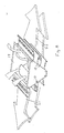
Figur 4 oder 5 mit maximaler Schrägstellung der beiden Teilluftströme, - Fig. 7 perspektivisch eine weitere Ausführungsform mit rechtwinklig zueinander angeordneten Austrittsöffnungen, wobei die Lamellen beider Austrittsöffnungen einen senkrechten Luftstrom erzeugen;
- Fig. 8 perspektivisch die Ausführungsform nach Fig. 7 mit einer Lamellenstellung, die zwei waagerechte Luftströme erzeugt,
- Fig. 9 in Seitenansicht eine der Fig. 7 ähnliche Ausführungsform mit rechtwinklig zueinander angeordneten Austrittsöffnungen, wobei die Lamellen beider Austrittsöffnungen einen senkrechten Luftstrom erzeugen und
- Fig. 10 in Seitenansicht eine der Fig. 8 ähnliche Ausführungsform mit einer Lamellenstellung, die zwei waagerechte Luftströme erzeugt.
- 1 shows a vertical section through an air guiding device on the wall of a room with an air flow directed horizontally into the room;
- 2 shows an air guiding device according to FIG. 1 in a middle inclined position;
- 3 shows an air guiding device according to FIGS. 1 and 2 with maximum inclination;
- Fig. 4 with a vertical section through an air guide on the ceiling of a room air flow directed vertically downwards with maximum exit velocity;
- 5 shows an air guiding device according to FIG. 4, the air flow of which is divided into two inclined partial air flows,
- 6 shows an air guiding device according to FIG. 4 or 5 with the maximum inclination of the two partial air flows,
- 7 is a perspective view of a further embodiment with outlet openings arranged at right angles to one another, the lamellae of both outlet openings generating a vertical air flow;
- 8 is a perspective view of the embodiment according to FIG. 7 with a slat position which generates two horizontal air flows,
- FIG. 9 shows a side view of an embodiment similar to FIG. 7 with outlet openings arranged at right angles to one another, the lamellae of both outlet openings generating a vertical air flow and
- Fig. 10 in side view of an embodiment similar to Fig. 8 with a slat position that generates two horizontal air flows.
Die Vorrichtung weist mehrere Lamellen 1a, 1b auf, die auch Flachprofile, Klappen, Leitbleche, Jalousieprofile genannt werden können und von denen je zwei 1a, 1b ein Lamellenpaar 2 bilden. Hierzu sind die Lamellen 1a, 1b mit ihrem einen Ende an einer Achse 3 angelenkt. Diese Achse 3 ist auf der der Luftstromquelle zugewandten Seite des Lamellenpaars, so daß die anströmende Luft 4 zuerst auf die Achse 3 auftrifft und danach in Luftkanäle 5 gelangt, die jeweils zwischen den Lamellenpaaren 2 gebildet werden. Damit bilden die einander benachbarten Lamellen 1a, 1b zweier verschiedener Lamellenpaare zwischen sich jeweils einen Luftkanal, der in Anströmrichtung 6 zur Außenseite hin sich verjüngt. Die Drehachse ist in Strömungsrichtung mit einem Radius versehen, der eine aerodynamisch günstige Anströmung der Luftkanäle gewährleistet.The device has a plurality of
Die um die Achse 3 drehverstellbaren Lamellen 1a, 1b können so verstellt werden, daß der Zwischenraum 7 zwischen zwei Lamellen eines Lamellenpaars 2 kleiner wird und der Luftkanal 5 größer als auch der Zwischenraum größer und der Luftkanal 5 entsprechend kleiner. In dem in Figur 1 bis 3 dargestellten Ausführungsbeispiel zeigt die in Figur 1 zu ersehene Stellung eine minimale Breite B der Luftkanäle 5, so daß die hierdurch austretende Luft eine sehr hohe Geschwindigkeit und damit eine große Raumtiefe erreicht. Hierbei ist die Ausströmrichtung 8 gleich oder parallel zur Anströmrichtung 6.The
Soll die Ausströmrichtung 8 schräg zur Anströmrichtung 6 sein, so werden die Lamellen 1a nicht um dengleichen Drehwinkel verstellt wie die Lamellen 1b, sondern eine der beiden Lamellenarten 1a oder 1b wird stärker verdreht als die andere, so daß die in Figur 2 dargestellte schräge Mittelstellung erreicht wird. Aufgrund der größeren Breite B ist hier die Ausströmgeschwindigkeit geringer als bei Figur 1, so daß die geringeren Austrittsgeschwindigkeiten der Zuluft eine geringere Eindringtiefe bewirken. Werden die Lamellen noch stärker in Schräglage verschwenkt, wobei wiederum die Lamellen 1a stärker nach unten entgegen dem Uhrzeigersinn verdreht werden als die Lamellen 1b, so wird die in Figur 3 dargestellte Stellung erzeugt, bei der der größte freie Strömungsquerschnitt (B Maximum) und eine maximale Schrägstellung und damit Ausströmablenkung geschaffen wird. Die erreichte Eindringtiefe ist verhältnismäßig gering aber die Luftumlenkung verhältnismäßig groß.If the
Das gleichmäßige Verstellen aller Lamellen 1a, 1b, wobei die Lamellen 1a jeweils parallel zueinander liegen und gleichmäßig drehverstellt werden und die Lamellen 1b auch stets zueinander parallel verbleiben und um andere Drehwinkel verstellt werden, wird durch ein Gestänge 9 erzeugt, daß aus rechtwinklig zur anströmenden Luft 4 liegenden Stangen 10 und 11 besteht, wobei die Stange 10 alle Lamellen 1a und die Stange 11 alle Lamellen 1b über Gelenk 12 miteinander verbindet. Durch diese Befestigungsart ist sichergestellt, daß alle Lamellen 1a dieselben Drehbewegungen ausführen. Das gleiche gilt für die Lamellen 1b. Darüber hinaus ist zumindest eine Lamelle 1a über eine schräge Gelenkstange 13 mit einer Lamelle 1b verbunden, wobei diese Gelenkstange 13 schräg zur anströmenden Luft und zu den Stangen 10, 11 ist. Damit ist die Anlenkstelle 14 der Stange 13 an der Lamelle 1b in einem unterschiedlichen Abstand A1 als der Abstand A2 der Anlenkstelle 15 der Stange 13 an der Lamelle 1a zur Achse 3.The uniform adjustment of all
Die Gelenke und Anlenkstellen können durch Schraubkanäle 16 gebildet sein, die an den Innenseiten der Lamellen angeformt sind. Die Außenflächen der Lamellen 1a, 1b sind konvex geformt, so daß die Luftkanäle düsenförmig arbeiten.The joints and articulation points can be formed by
Das Ausführungsbeispiel nach Figuren 4 bis 6 unterscheidet sich von dem nach den Figuren 1 bis 3 dadurch, daß ein Teil 2a der Lamellen zu einer Seite verschwenkbar ist und der andere Teil 2b der Lamellen zur anderen Seite, so daß der anströmende Luftstrom geteilt wird. Ein solches Aufteilen des Luftstroms nach zwei entgegengesetzten Seiten ist besonders dann von Vorteil, wenn der Luftauslaß sich an der Decke eines Raumes oder einer Halle befindet.The exemplary embodiment according to FIGS. 4 to 6 differs from that according to FIGS. 1 to 3 in that
Bei diesem Ausführungsbeispiel nach Fig. 4 bis 6 ist das Gestänge in jeweils zwei Stangenpaare 10, 11 aufgeteilt, von denen ein Stangenpaar einen Lamellenteil 2a und das andere Stangenpaar den zweiten Lamellenteil 2b steuert. Hierbei sind an den Stangen Betätigungsstangen so angelenkt, daß bei einem Verschwenken der Lamellen eines Teils 2a oder Hälfte der andere Teil 2b oder die andere Hälfte in entgegengesetzter Drehrichtung verschwenkt. Die Lamellen 1a, 1b eines einzigen Lamellenpaares 2 bilden zwischen sich den Zwischenraum 7, der zu den Stirnseiten hin offen ist, um Sekundärluft eintreten zu lassen. Diese Sekundärluft strömt dann in Ausströmrichtung 8 aus, da sie von der durch die Luftkanäle 5 hindurchströmenden Luft mitgenommen wird. Hierbei ist von Bedeutung, daß der kleinste Freiströmungsquerschnitt des Luftkanals 5 sich weit vorne an den freien Enden der Lamellen 1a, 1b befindet. Um auf besonders einfache Weise einen freien Eintritt von Sekundärluft in die Zwischenräume 7 zu gewährleisten sind die Lamellen so weit vor dem Auslaß eines Gerätes oder eines Luftkanals angeordnet, daß die Stirnseiten frei sind.In this embodiment according to FIGS. 4 to 6, the linkage is divided into two pairs of
Im Ausführungsbeispiel nach den Figuren 7 und 8 sind eine Hälfte der Lamellen und damit vier Lamellen 1a, 1b am Rand einer ersten Austrittsöffnung 17 befestigt, die 45 ° geneigt zur Eintrittsöffnung 19 liegt, wobei die zweite Austrittsöffnung 18 einen Winkel von 90 ° zur ersten Austrittsöffnung 17 und einen Winkel von 45 ° zur Eintrittsöffnung 19 bildet. Die drei Öffnungen 17, 18, 19 bilden damit ein gerades Prisma mit einem rechtwinkligen und gleichschenkligen Dreieck als Grundfläche. Alternativ können auch vier Austrittsöffnungen vorgesehen sein, die einen Pyramidenstumpf bilden, dessen Grundfläche die Eintrittsöffnung bildet. Hierbei kann die obere zur Eintrittsöffnung parallele Fläche des Stumpfes eine weitere Austrittsöffnung bilden.In the exemplary embodiment according to FIGS. 7 and 8, one half of the lamellae and thus four
In der senkrechten Lamellenstellung nach Figur 7 bilden die Luftströme beider Austrittsöffnungen 17, 18 einen senkrechten Gesamtluftstrom 20 und in der Stellung nach Figur 8 zwei Teilluftströme 21, 22, die waagerecht entgegengesetzt gerichtet sind und damit entlang der Decke einer Halle oder Raumes strömen.In the vertical lamella position according to FIG. 7, the air flows of both
Die Ausführungsform nach den Fig. 9 und 10 unterscheidet sich von der nach Fig. 7 und 8 im wesentlichen dadurch, daß die die Lamellen 1a, 13 verbindenden Stangen 10, 11, 13 dargestellt sind und zwischen den innersten und damit untersten zwei Lamellen im Gehäuseinnern ein rechtwinklig abgebogenes Luftleitblech 23 angeordnet ist, das einen Luftstrom zwischen diesen zwei Lamellen verhindert.The embodiment according to FIGS. 9 and 10 differs from that according to FIGS. 7 and 8 essentially in that the
Claims (14)
dadurch gekennzeichnet, daß die Lamellen (1a, 1b) derart durch Verschwenken verstellbar sind, daß bei einer Strömungsrichtung (8) in und nach den Luftkanälen (5) in Richtung der anströmenden Luft (6) die Luftkanäle (5) eine kleinere Breite (B) aufweisen als in einer zur anströmenden Luft (6) schrägen Richtung.1. Device for guiding an air flow through mutually parallel slats, which are arranged at the outlet of an air flow-guiding, in particular generating device, wherein two slats are rotatably articulated with their side longitudinal edges facing the air flow source on one axis or two axles lying close to each other to form a pair of fins which forms air ducts with adjacent pairs of fins, the width of which can be changed by pivoting the fins,
characterized in that the lamellae (1a, 1b) can be adjusted by pivoting such that in a direction of flow (8) in and after the air ducts (5) in the direction of the incoming air (6) the air ducts (5) have a smaller width (B ) than in an oblique direction to the incoming air (6).
dadurch gekennzeichnet, daß die Lamellen (1a, 1b) durch ein Gestänge (9, 10, 11) verstellbar sind.2. Device according to claim 1,
characterized in that the slats (1a, 1b) are adjustable by means of a linkage (9, 10, 11).
dadurch gekennzeichnet, daß jede zweite Lamelle (1a) an einer ersten zur anströmenden Luft rechtwinkligen Stange (10) angelenkt ist und die übrigen Lamellen (1b) an einer zweiten Stange (11).3. Device according to claim 2,
characterized in that each second lamella (1a) is articulated on a first rod (10) perpendicular to the incoming air and the remaining lamellae (1b) on a second rod (11).
dadurch gekennzeichnet, daß ein Teil (2a), insbesondere etwa eine Hälfte der nebeneinander liegenden Lamellenpaare (2) unabhängig von den Lamellenpaaren (2) des anderen Teils (2b) bzw. Hälfte verstellbar ist.4. Apparatus according to claim 2 or 3,
characterized in that a part (2a), in particular about half of the pairs of plates (2) lying next to one another, is adjustable independently of the plate pairs (2) of the other part (2b) or half.
dadurch gekennzeichnet, daß die Lamellen (1a, 1b) in der Weise miteinander gekoppelt sind, daß bei einer Verstellung des einen Lamellenteils (2a) nach außen der andere Lamellenteil (2b) in die entgegengesetzte Richtung nach außen verstellt wird.5. The device according to claim 4,
characterized in that the slats (1a, 1b) are coupled to one another in such a way that when one slat part (2a) is moved outwards, the other slat part (2b) is moved outwards in the opposite direction.
dadurch gekennzeichnet, daß die Lamellen (1a, 1b) einen gewölbten Querschnitt aufweisen, wobei die Außenflächen, die den Luftkanal bilden, konvex geformt sind.6. Device according to one of the preceding claims,
characterized in that the lamellae (1a, 1b) have a curved cross section, the outer surfaces forming the air duct being convex.
dadurch gekennzeichnet, daß an den Lamelleninnenseiten längsangeordnete Schraubkanäle (16) angeformt sind.7. Device according to one of the preceding claims,
characterized in that longitudinally arranged screw channels (16) are formed on the inside of the slats.
dadurch gekennzeichnet, daß mindestens eine Lamelle (1a) eines Lamellenpaares (2) mit derjenigen Lamelle (1b) eines anderen Lamellenpaares (2), die nicht parallel zur ersten Lamelle (1a) steht, über eine Gelenkstange (13) verbunden ist, wobei die beiden Anlenkstellen (14, 15) in unterschiedlichen Abständen (A1) und (A2) zu den Achsen (3) liegen.8. Device according to one of the preceding claims,
characterized in that at least one slat (1a) of a pair of slats (2) with that slat (1b) of another pair of slats (2), which is not parallel to the first slat (1a), is connected via an articulated rod (13), the two articulation points (14, 15) are at different distances (A1) and (A2) from the axes (3).
dadurch gekennzeichnet, daß die seitlichen Stirnseiten des Zwischenraumes (7) jeden Lamellenpaares (2) offen sind um Sekundärluft eintreten zu lassen.9. Device according to one of the preceding claims,
characterized in that the lateral end faces of the intermediate space (7) of each pair of fins (2) are open to allow secondary air to enter.
dadurch gekennzeichnet, daß für einen freien Eintritt von Sekundärluft in die Zwischenräume (7) die Lamellenpaare (2) vor dem Auslaß befestigt sind.10. The device according to claim 9,
characterized in that for a free entry of secondary air into the intermediate spaces (7), the pairs of fins (2) are fastened in front of the outlet.
dadurch gekennzeichnet, daß die Achsen (3) einer Anzahl, insbesondere einer Hälfte der Lamellen (1a, 1b) in einer Ebene liegen, die zur Ebene der übrigen Achsen (3) in einem Winkel (α) liegt.11. Device according to one of the preceding claims,
characterized in that the axes (3) of a number, in particular one half, of the lamellae (1a, 1b) lie in a plane which is at an angle (α) to the plane of the other axes (3).
dadurch gekennzeichnet, daß der Winkel (α) 30 bis 120 °, insbesondere ca. 90 ° beträgt.12. The device according to claim 11,
characterized in that the angle (α) is 30 to 120 °, in particular approximately 90 °.
dadurch gekennzeichnet, daß die Lamellen (1a, 1b) an den Seiten eines Pyramidenstumpfes angelenkt sind.13. The apparatus of claim 11 or 12,
characterized in that the lamellae (1a, 1b) are articulated on the sides of a truncated pyramid.
dadurch gekennzeichnet, daß die Achsen (3) der Lamellen (1a, 1b) in einer Zylinderfläche liegen.14. The device according to one of claims 1 to 10,
characterized in that the axes (3) of the fins (1a, 1b) lie in a cylindrical surface.
Priority Applications (1)
| Application Number | Priority Date | Filing Date | Title |
|---|---|---|---|
| AT87115721T ATE57251T1 (en) | 1986-11-12 | 1987-10-27 | DEVICE FOR DIRECTING AN AIR FLOW. |
Applications Claiming Priority (2)
| Application Number | Priority Date | Filing Date | Title |
|---|---|---|---|
| DE3638614 | 1986-11-12 | ||
| DE19863638614 DE3638614A1 (en) | 1986-11-12 | 1986-11-12 | DEVICE FOR CONDUCTING AN AIRFLOW |
Publications (3)
| Publication Number | Publication Date |
|---|---|
| EP0267486A2 true EP0267486A2 (en) | 1988-05-18 |
| EP0267486A3 EP0267486A3 (en) | 1989-03-15 |
| EP0267486B1 EP0267486B1 (en) | 1990-10-03 |
Family
ID=6313759
Family Applications (1)
| Application Number | Title | Priority Date | Filing Date |
|---|---|---|---|
| EP87115721A Expired - Lifetime EP0267486B1 (en) | 1986-11-12 | 1987-10-27 | Device for guiding an air stream |
Country Status (6)
| Country | Link |
|---|---|
| EP (1) | EP0267486B1 (en) |
| AT (1) | ATE57251T1 (en) |
| DD (1) | DD262892A5 (en) |
| DE (2) | DE3638614A1 (en) |
| ES (1) | ES2018230B3 (en) |
| GR (1) | GR3001241T3 (en) |
Cited By (6)
| Publication number | Priority date | Publication date | Assignee | Title |
|---|---|---|---|---|
| DE3914241A1 (en) * | 1989-04-29 | 1990-10-31 | Happel Gmbh & Co | DEVICE FOR CONDUCTING AN AIRFLOW |
| EP0699876A2 (en) | 1994-09-02 | 1996-03-06 | TTL Tür + Torluftschleier Lufttechnische Geräte GmbH | Air outlet |
| AT400896B (en) * | 1992-06-17 | 1996-04-25 | Troges Gmbh | Rotatable slat |
| AT407297B (en) * | 1992-03-19 | 2001-02-26 | Kubag Consulting Ag | CONTROL VALVE |
| CN104764182A (en) * | 2015-02-13 | 2015-07-08 | 广东美的制冷设备有限公司 | Louver mechanism and air outlet device with same |
| US20220333798A1 (en) * | 2015-03-05 | 2022-10-20 | Vornado Air, Llc | Air Circulator with Vein Control System |
Families Citing this family (4)
| Publication number | Priority date | Publication date | Assignee | Title |
|---|---|---|---|---|
| JPH068517Y2 (en) * | 1989-03-10 | 1994-03-02 | トヨタ自動車株式会社 | Fluctuating wind generator |
| DE4133734A1 (en) * | 1991-10-11 | 1993-04-22 | Gea Happel Klimatechnik | AIR HEATING AND / OR COOLING UNIT |
| DE4305928C2 (en) * | 1993-02-26 | 1997-09-11 | Rahmer & Jansen Gmbh | Device and method for cooling liquid and gaseous media using air |
| FR2729461B1 (en) * | 1995-01-17 | 1997-04-18 | Cerga | DEVICE FOR ADJUSTING THE PASSAGE SECTION OF A VENTILATION AIR VENT OF A PREMISES |
Citations (1)
| Publication number | Priority date | Publication date | Assignee | Title |
|---|---|---|---|---|
| US2224312A (en) * | 1935-01-17 | 1940-12-10 | Preferred Utilities Company In | Permanent outlet control device |
Family Cites Families (1)
| Publication number | Priority date | Publication date | Assignee | Title |
|---|---|---|---|---|
| US2799989A (en) * | 1954-09-24 | 1957-07-23 | Peter G Kappus | Variable area jet nozzle |
-
1986
- 1986-11-12 DE DE19863638614 patent/DE3638614A1/en not_active Withdrawn
-
1987
- 1987-10-27 DE DE8787115721T patent/DE3765388D1/en not_active Expired - Fee Related
- 1987-10-27 ES ES87115721T patent/ES2018230B3/en not_active Expired - Lifetime
- 1987-10-27 AT AT87115721T patent/ATE57251T1/en not_active IP Right Cessation
- 1987-10-27 EP EP87115721A patent/EP0267486B1/en not_active Expired - Lifetime
- 1987-11-10 DD DD87308886A patent/DD262892A5/en not_active IP Right Cessation
-
1990
- 1990-12-27 GR GR90400838T patent/GR3001241T3/en unknown
Patent Citations (1)
| Publication number | Priority date | Publication date | Assignee | Title |
|---|---|---|---|---|
| US2224312A (en) * | 1935-01-17 | 1940-12-10 | Preferred Utilities Company In | Permanent outlet control device |
Cited By (11)
| Publication number | Priority date | Publication date | Assignee | Title |
|---|---|---|---|---|
| DE3914241A1 (en) * | 1989-04-29 | 1990-10-31 | Happel Gmbh & Co | DEVICE FOR CONDUCTING AN AIRFLOW |
| EP0395870A2 (en) * | 1989-04-29 | 1990-11-07 | GEA Happel Klimatechnik GmbH | Device for guiding an air stream |
| EP0395870A3 (en) * | 1989-04-29 | 1991-12-27 | GEA Happel Klimatechnik GmbH | Device for guiding an air stream |
| AT407297B (en) * | 1992-03-19 | 2001-02-26 | Kubag Consulting Ag | CONTROL VALVE |
| AT400896B (en) * | 1992-06-17 | 1996-04-25 | Troges Gmbh | Rotatable slat |
| EP0699876A2 (en) | 1994-09-02 | 1996-03-06 | TTL Tür + Torluftschleier Lufttechnische Geräte GmbH | Air outlet |
| EP0699876A3 (en) * | 1994-09-02 | 1997-06-11 | Ttl Tuer & Torluftschleier Luf | Air outlet |
| CN104764182A (en) * | 2015-02-13 | 2015-07-08 | 广东美的制冷设备有限公司 | Louver mechanism and air outlet device with same |
| CN104764182B (en) * | 2015-02-13 | 2018-05-01 | 广东美的制冷设备有限公司 | Shutter mechanism and there is its exhaust apparatus |
| US20220333798A1 (en) * | 2015-03-05 | 2022-10-20 | Vornado Air, Llc | Air Circulator with Vein Control System |
| US11519616B2 (en) * | 2015-03-05 | 2022-12-06 | Vornado Air, Llc | Air circulator with vane control system |
Also Published As
| Publication number | Publication date |
|---|---|
| EP0267486A3 (en) | 1989-03-15 |
| ES2018230B3 (en) | 1991-04-01 |
| DD262892A5 (en) | 1988-12-14 |
| DE3765388D1 (en) | 1990-11-08 |
| ATE57251T1 (en) | 1990-10-15 |
| DE3638614A1 (en) | 1988-05-26 |
| EP0267486B1 (en) | 1990-10-03 |
| GR3001241T3 (en) | 1992-07-30 |
Similar Documents
| Publication | Publication Date | Title |
|---|---|---|
| DE10157408B4 (en) | incoming air | |
| WO2015062890A1 (en) | Air nozzle | |
| WO2019020489A1 (en) | Outflow nozzle of a motor vehicle | |
| DE3437259C2 (en) | ||
| DE69529913T2 (en) | Air baffle | |
| EP0267486B1 (en) | Device for guiding an air stream | |
| DE2556538B2 (en) | Arrangement for ventilation and / or temperature control of a room | |
| EP0335151B1 (en) | Air exit for creating a displacement-flow with poor turbulence | |
| EP0267485B1 (en) | Device for guiding an air stream | |
| EP0361213A1 (en) | Air diffuser for interior spaces, particularly for the interior of an automotive vehicle | |
| EP0360147B1 (en) | Outlet with a vortex flow | |
| EP0149752B1 (en) | Rectangular air outlet for a room air conditioning system | |
| DE102009020574B3 (en) | Air outlet nozzle for use in ventilating system to control air flow of motor vehicle, has two flaps that function as air deflector chute for further deflection of air flow deflected by air deflection element in one of flap positions | |
| DE2033195B2 (en) | Air conditioning system outlet - has main discharge for mixed primary and secondary air from induction conditioner | |
| DE202021104865U1 (en) | A vehicle ventilator comprising magnetically orientable deflector elements | |
| EP0667496B1 (en) | Air ventilation box | |
| DE2525977C2 (en) | Ventilation grille for indoor ventilation | |
| DE3231486C2 (en) | ||
| DE2105718C3 (en) | Slot fan for installation in building ceilings | |
| DE2810383C2 (en) | Blow-out unit with regulation or shifting of the amount of air to be blown out | |
| EP0239854B1 (en) | Air outlet | |
| EP4224077A1 (en) | Air outlet | |
| DE7500088U (en) | SLOT OUTLET FOR AIR CONDUCTION IN AIR TECHNOLOGY EQUIPMENT ETC. | |
| DE2830363B1 (en) | Blow-out unit | |
| DE1105587B (en) | Air duct for ventilation systems |
Legal Events
| Date | Code | Title | Description |
|---|---|---|---|
| PUAI | Public reference made under article 153(3) epc to a published international application that has entered the european phase |
Free format text: ORIGINAL CODE: 0009012 |
|
| AK | Designated contracting states |
Kind code of ref document: A2 Designated state(s): AT BE CH DE ES FR GB GR IT LI NL SE |
|
| PUAL | Search report despatched |
Free format text: ORIGINAL CODE: 0009013 |
|
| AK | Designated contracting states |
Kind code of ref document: A3 Designated state(s): AT BE CH DE ES FR GB GR IT LI NL SE |
|
| 17P | Request for examination filed |
Effective date: 19890225 |
|
| 17Q | First examination report despatched |
Effective date: 19890629 |
|
| GRAA | (expected) grant |
Free format text: ORIGINAL CODE: 0009210 |
|
| AK | Designated contracting states |
Kind code of ref document: B1 Designated state(s): AT BE CH DE ES FR GB GR IT LI NL SE |
|
| REF | Corresponds to: |
Ref document number: 57251 Country of ref document: AT Date of ref document: 19901015 Kind code of ref document: T |
|
| GBT | Gb: translation of ep patent filed (gb section 77(6)(a)/1977) | ||
| REF | Corresponds to: |
Ref document number: 3765388 Country of ref document: DE Date of ref document: 19901108 |
|
| ET | Fr: translation filed | ||
| ITF | It: translation for a ep patent filed |
Owner name: SOCIETA' ITALIANA BREVETTI S.P.A. |
|
| PLBE | No opposition filed within time limit |
Free format text: ORIGINAL CODE: 0009261 |
|
| STAA | Information on the status of an ep patent application or granted ep patent |
Free format text: STATUS: NO OPPOSITION FILED WITHIN TIME LIMIT |
|
| 26N | No opposition filed | ||
| ITTA | It: last paid annual fee | ||
| REG | Reference to a national code |
Ref country code: GR Ref legal event code: FG4A Free format text: 3001241 |
|
| EAL | Se: european patent in force in sweden |
Ref document number: 87115721.0 |
|
| REG | Reference to a national code |
Ref country code: GB Ref legal event code: IF02 |
|
| PGFP | Annual fee paid to national office [announced via postgrant information from national office to epo] |
Ref country code: GR Payment date: 20040924 Year of fee payment: 18 |
|
| PGFP | Annual fee paid to national office [announced via postgrant information from national office to epo] |
Ref country code: NL Payment date: 20041003 Year of fee payment: 18 |
|
| PGFP | Annual fee paid to national office [announced via postgrant information from national office to epo] |
Ref country code: SE Payment date: 20041006 Year of fee payment: 18 |
|
| PGFP | Annual fee paid to national office [announced via postgrant information from national office to epo] |
Ref country code: FR Payment date: 20041008 Year of fee payment: 18 |
|
| PGFP | Annual fee paid to national office [announced via postgrant information from national office to epo] |
Ref country code: AT Payment date: 20041013 Year of fee payment: 18 |
|
| PGFP | Annual fee paid to national office [announced via postgrant information from national office to epo] |
Ref country code: DE Payment date: 20041021 Year of fee payment: 18 |
|
| PGFP | Annual fee paid to national office [announced via postgrant information from national office to epo] |
Ref country code: CH Payment date: 20041027 Year of fee payment: 18 Ref country code: GB Payment date: 20041027 Year of fee payment: 18 |
|
| PGFP | Annual fee paid to national office [announced via postgrant information from national office to epo] |
Ref country code: ES Payment date: 20041116 Year of fee payment: 18 |
|
| PGFP | Annual fee paid to national office [announced via postgrant information from national office to epo] |
Ref country code: BE Payment date: 20041215 Year of fee payment: 18 |
|
| PG25 | Lapsed in a contracting state [announced via postgrant information from national office to epo] |
Ref country code: IT Free format text: LAPSE BECAUSE OF NON-PAYMENT OF DUE FEES Effective date: 20051027 Ref country code: AT Free format text: LAPSE BECAUSE OF NON-PAYMENT OF DUE FEES Effective date: 20051027 |
|
| PG25 | Lapsed in a contracting state [announced via postgrant information from national office to epo] |
Ref country code: SE Free format text: LAPSE BECAUSE OF NON-PAYMENT OF DUE FEES Effective date: 20051028 Ref country code: ES Free format text: LAPSE BECAUSE OF NON-PAYMENT OF DUE FEES Effective date: 20051028 |
|
| PG25 | Lapsed in a contracting state [announced via postgrant information from national office to epo] |
Ref country code: CH Free format text: LAPSE BECAUSE OF NON-PAYMENT OF DUE FEES Effective date: 20051031 Ref country code: BE Free format text: LAPSE BECAUSE OF NON-PAYMENT OF DUE FEES Effective date: 20051031 Ref country code: LI Free format text: LAPSE BECAUSE OF NON-PAYMENT OF DUE FEES Effective date: 20051031 |
|
| PG25 | Lapsed in a contracting state [announced via postgrant information from national office to epo] |
Ref country code: NL Free format text: LAPSE BECAUSE OF NON-PAYMENT OF DUE FEES Effective date: 20060501 |
|
| PG25 | Lapsed in a contracting state [announced via postgrant information from national office to epo] |
Ref country code: DE Free format text: LAPSE BECAUSE OF NON-PAYMENT OF DUE FEES Effective date: 20060503 |
|
| REG | Reference to a national code |
Ref country code: CH Ref legal event code: PL |
|
| EUG | Se: european patent has lapsed | ||
| GBPC | Gb: european patent ceased through non-payment of renewal fee |
Effective date: 20051027 |
|
| PG25 | Lapsed in a contracting state [announced via postgrant information from national office to epo] |
Ref country code: FR Free format text: LAPSE BECAUSE OF NON-PAYMENT OF DUE FEES Effective date: 20060630 |
|
| NLV4 | Nl: lapsed or anulled due to non-payment of the annual fee |
Effective date: 20060501 |
|
| REG | Reference to a national code |
Ref country code: FR Ref legal event code: ST Effective date: 20060630 |
|
| REG | Reference to a national code |
Ref country code: ES Ref legal event code: FD2A Effective date: 20051028 |
|
| BERE | Be: lapsed |
Owner name: *HAPPEL G.M.B.H. & CO. Effective date: 20051031 |
|
| PG25 | Lapsed in a contracting state [announced via postgrant information from national office to epo] |
Ref country code: GR Free format text: LAPSE BECAUSE OF NON-PAYMENT OF DUE FEES Effective date: 19901003 |