EP0266448A1 - Machine à imprimer avec des pochoirs cylindriques ou avec des cylindres imprimeurs avec au moins deux unités d'impression - Google Patents
Machine à imprimer avec des pochoirs cylindriques ou avec des cylindres imprimeurs avec au moins deux unités d'impression Download PDFInfo
- Publication number
- EP0266448A1 EP0266448A1 EP86115300A EP86115300A EP0266448A1 EP 0266448 A1 EP0266448 A1 EP 0266448A1 EP 86115300 A EP86115300 A EP 86115300A EP 86115300 A EP86115300 A EP 86115300A EP 0266448 A1 EP0266448 A1 EP 0266448A1
- Authority
- EP
- European Patent Office
- Prior art keywords
- printing
- machine according
- printing machine
- hub
- units
- Prior art date
- Legal status (The legal status is an assumption and is not a legal conclusion. Google has not performed a legal analysis and makes no representation as to the accuracy of the status listed.)
- Withdrawn
Links
Images
Classifications
-
- B—PERFORMING OPERATIONS; TRANSPORTING
- B41—PRINTING; LINING MACHINES; TYPEWRITERS; STAMPS
- B41F—PRINTING MACHINES OR PRESSES
- B41F13/00—Common details of rotary presses or machines
- B41F13/0008—Driving devices
-
- B—PERFORMING OPERATIONS; TRANSPORTING
- B41—PRINTING; LINING MACHINES; TYPEWRITERS; STAMPS
- B41F—PRINTING MACHINES OR PRESSES
- B41F15/00—Screen printers
- B41F15/08—Machines
- B41F15/0831—Machines for printing webs
- B41F15/0836—Machines for printing webs by means of cylindrical screens or screens in the form of endless belts
Definitions
- the invention relates to a circular stencil or roller printing machine with at least two printing units, one of which is arranged in the working position, i.e. a machine with sample cylinders.
- a counter roller or the like is arranged in a stationary manner as a printing base and that the two printing units are arranged so as to be relatively movable and optionally drivable.
- the printing pad is arranged in a fixed position during operation of the machine and two print heads each with a pattern cylinder are assigned, the print heads being able to be arranged on movable supports which can be moved in opposite directions via at least one drive and one of which is in the working position when the other is at rest.
- the printing press has a synchronous clutch, which connects one of the two print heads to the repeat gear.
- the ink supply to the sample cylinder brought out of the working position is automatically interrupted and the ink supply to the sample cylinder brought into the working position is automatically switched on after reaching the working position.
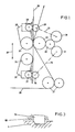
- FIG. 1 shows the possibility of the change process shown schematically.
- 2 shows a section through the synchronous clutch and
- FIG. 3 shows a detail of this clutch.
- FIG. 1 shows schematically how a pattern cylinder change can be carried out without it being necessary to switch off the printing press as before during this pattern cylinder change.
- a web of material 20 is guided over deflecting rollers 21 via a magnetic roller 22, which serves as a printing pad.
- the position of the magnetic roller 22 is fixed in the machine, so that a predetermined fabric tension is given by the rollers 21, the magnetic roller 22 and the pulling force of the web 20 during the entire operation.
- the magnetic roller is assigned two sample cylinders 23, 24, which are each arranged in print heads 25 and 26, which in turn have holders 27 and 28.
- the holder 27 together with the print head 26 or the holder 28 with the print head 25 can be moved in the plane 29, namely by the distance 37.
- the pattern cylinder 23 is in its working position, whereas the pattern cylinder 24 is is in its rest position. Ie the sample cylinder 23 rotates with the prescribed pro production speed, whereas the pattern cylinder 24 has no speed. That is, during the operation of the pattern cylinder 23, the pattern cylinder 24 can be changed in the usual manner without difficulty.
- the holders 27, 28 are moved in the plane 29 by a drive (not shown). For this purpose, one will briefly switch off the electromagnets of the magnetic roller 22, lift the sample cylinder 23 somewhat from the web 20 and then move the holder 28 upwards in FIG. At the same time, the holder 27 is also moved upward, so that the pattern cylinder 24 comes into the position above the magnetic roller 22, where it is lowered, and then the electromagnets of the magnetic roller 22 are switched on again.
- the pattern cylinders 23 and 24 it is expedient first to arrange the components arranged in their interior, e.g. Ink container, ink tube, squeegee device to lift off, on the one hand to interrupt the ink supply and on the other hand to avoid damage to the mostly thin-walled screen cylinder.
- the reverse process is then carried out, i.e. first the sample cylinder is brought into the working position and then the internal components are lowered, i.e. the ink supply is opened and the doctor blade is pressed against the sample cylinder wall.
- a repeat gear 30 is provided, which in the embodiment of FIG. 1 engages with the magnetic roller 22 and two synchronous clutches 31. Each of these two synchronous clutches is connected via a repeat shaft 35 to the drive gear 36 of the sample cylinder.
- the synchronous clutch assigned to it is actuated, whereas the sample cylinder to be brought into the rest position is uncoupled by its synchronous clutch and is then stopped automatically.
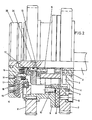
- a suitable synchronous clutch is shown in FIG.
- rappor wheels 11 are attached, which constantly rotate about the axis 1.
- the gearshift sleeve carries a gearshift claw 34, the axis 1 is also surrounded by a second hub 4, with which the gear 7 to be driven is screwed, that is, the gear which is to be synchronized with the rappor gear 11.
- the hub is mounted on the axle 1 via a ball bearing 2.
- two grooves 3 of different widths are milled axially, into which the shifting claws 34 can only latch exactly at one point without play.
- a disc 33 With the axis 1, a disc 33 is fixedly connected, and this disc is provided with two compressed air connections and a vent hole.
- An air bellows 17 is supported on the inside of the disk 33. If compressed air is applied to this air bellows 7, the force of this compressed air acts via a pressure plate 16 on the ball bearing 15, on the hub 9, which is opposed by a friction lining 8. Contact is made with the friction lining and this is pressed against the gear 7 to be driven. As a result, the acceleration of this gear wheel from zero to synchronism with the rappor wheel 11 is within less seconds.
- the disk 33 there is also a connection to a piston 12, which presses the circumferential shifting claw 34 against the hub 4 via the ball bearing 19.
- a latching of the switching claw 34 in the groove 3 is only possible at a certain point.
- the compressed air is released from the air bellows 17 via a throttle.
- the clutch begins to slip again, however, until the shifting claw 34 engages in the groove 3. That is, only the circuit with the piston 12 remains pressurized air as long as the printing process of this sample cylinder driven by the gearwheel 7 continues.
- the friction clutch 8 has only the function of a starting clutch and is always actuated briefly.
- the switching claw 34 is reset by at least two springs 13, which come into action as soon as the application of compressed air to the piston 12 is ended. Spacers 32 are provided to limit the spring travel. The springs 13 bring the piston 12 into the starting position, and there is an air gap between the friction lining 8 and the gear 7 and also between the friction lining 8 and the hub 9.
- the synchronous clutch has two main functions, namely on the one hand the acceleration of the drive of the respective printing unit from standstill to the machine speed and on the other hand a defined, repeatable engagement.
- the first is essential, as this is the only way to couple at full speed and avoid knocks and breakage, the second function is essential for the quality of the manufactured goods.
Landscapes
- Engineering & Computer Science (AREA)
- Mechanical Engineering (AREA)
- Inking, Control Or Cleaning Of Printing Machines (AREA)
Priority Applications (1)
| Application Number | Priority Date | Filing Date | Title |
|---|---|---|---|
| EP86115300A EP0266448A1 (fr) | 1986-11-05 | 1986-11-05 | Machine à imprimer avec des pochoirs cylindriques ou avec des cylindres imprimeurs avec au moins deux unités d'impression |
Applications Claiming Priority (1)
| Application Number | Priority Date | Filing Date | Title |
|---|---|---|---|
| EP86115300A EP0266448A1 (fr) | 1986-11-05 | 1986-11-05 | Machine à imprimer avec des pochoirs cylindriques ou avec des cylindres imprimeurs avec au moins deux unités d'impression |
Publications (1)
| Publication Number | Publication Date |
|---|---|
| EP0266448A1 true EP0266448A1 (fr) | 1988-05-11 |
Family
ID=8195569
Family Applications (1)
| Application Number | Title | Priority Date | Filing Date |
|---|---|---|---|
| EP86115300A Withdrawn EP0266448A1 (fr) | 1986-11-05 | 1986-11-05 | Machine à imprimer avec des pochoirs cylindriques ou avec des cylindres imprimeurs avec au moins deux unités d'impression |
Country Status (1)
| Country | Link |
|---|---|
| EP (1) | EP0266448A1 (fr) |
Cited By (1)
| Publication number | Priority date | Publication date | Assignee | Title |
|---|---|---|---|---|
| GB2225286A (en) * | 1988-11-25 | 1990-05-30 | Schiavi Cesare Costr Mec | A trolley for print cylinder assemblies |
Citations (5)
| Publication number | Priority date | Publication date | Assignee | Title |
|---|---|---|---|---|
| DE537002C (de) * | 1927-05-03 | 1931-10-29 | Crabtree & Sons Ltd R | Vorrichtung zum Drucken der Ietzten Nachrichten an Zeitungs-Rotationsdruckmaschinen |
| DE1937986A1 (de) * | 1968-08-02 | 1970-02-05 | Draeger Freres | Helio-Rotationsdruckmaschine |
| GB1250921A (fr) * | 1969-06-09 | 1971-10-27 | ||
| DE3313219A1 (de) * | 1983-04-13 | 1984-10-18 | Metronic Gerätebau GmbH & Co, 8702 Veitshöchheim | Druckwerk fuer eine rotationsdruckmaschine |
| NL8402665A (nl) * | 1984-08-31 | 1986-03-17 | Stork Brabant Bv | Rotatiezeefdrukmachine voorzien van meervoudige drukstations. |
-
1986
- 1986-11-05 EP EP86115300A patent/EP0266448A1/fr not_active Withdrawn
Patent Citations (5)
| Publication number | Priority date | Publication date | Assignee | Title |
|---|---|---|---|---|
| DE537002C (de) * | 1927-05-03 | 1931-10-29 | Crabtree & Sons Ltd R | Vorrichtung zum Drucken der Ietzten Nachrichten an Zeitungs-Rotationsdruckmaschinen |
| DE1937986A1 (de) * | 1968-08-02 | 1970-02-05 | Draeger Freres | Helio-Rotationsdruckmaschine |
| GB1250921A (fr) * | 1969-06-09 | 1971-10-27 | ||
| DE3313219A1 (de) * | 1983-04-13 | 1984-10-18 | Metronic Gerätebau GmbH & Co, 8702 Veitshöchheim | Druckwerk fuer eine rotationsdruckmaschine |
| NL8402665A (nl) * | 1984-08-31 | 1986-03-17 | Stork Brabant Bv | Rotatiezeefdrukmachine voorzien van meervoudige drukstations. |
Cited By (3)
| Publication number | Priority date | Publication date | Assignee | Title |
|---|---|---|---|---|
| GB2225286A (en) * | 1988-11-25 | 1990-05-30 | Schiavi Cesare Costr Mec | A trolley for print cylinder assemblies |
| FR2639581A1 (fr) * | 1988-11-25 | 1990-06-01 | Schiavi Cesare Costr Mec | Chariot porte-groupe d'impression pour une station d'impression dans des machines rotatives |
| GB2225286B (en) * | 1988-11-25 | 1992-04-15 | Schiavi Cesare Costr Mec | A trolley for print cylinder assemblies used in the print stations of rotary machines |
Similar Documents
| Publication | Publication Date | Title |
|---|---|---|
| DE3742129C2 (fr) | ||
| EP0242661B1 (fr) | Dispositif de positionnement d'un ensemble d'impression à cinq cylindres d'une rotative offset | |
| DE3110468A1 (de) | Antrieb fuer funktionsgruppen in bogenfuehrungszylindern von druckmaschinen | |
| EP0010141B1 (fr) | Dispositif pour la production de produits imprimés avec des impressions interchangeables | |
| DE19530956A1 (de) | Vorrichtung zur Umstellung eines Sammelzylinders am Falzapparat | |
| DE10317283B4 (de) | Tampondruckmaschine | |
| EP1138484B1 (fr) | Machine pour imprimer où décorer des corps creux | |
| DE2642956C3 (de) | Vorrichtung zum Einstellen der Druckschablonen in einer Rotationsschablonendruckmaschine | |
| DE2537919B2 (de) | Umsteuerbarer Falzzylinder | |
| EP0266448A1 (fr) | Machine à imprimer avec des pochoirs cylindriques ou avec des cylindres imprimeurs avec au moins deux unités d'impression | |
| DE4444189C2 (de) | Durch- oder Siebdruckmaschine | |
| DE2553768C3 (de) | Rollen-Rotationsdruckmaschine | |
| DE19518588C2 (de) | Tampondruckmaschine | |
| DE1902916C2 (de) | Düsenbohrmaschine | |
| EP0805024A2 (fr) | Machine rotative d'impression sérigraphique pour imprimer des images grandes | |
| DE3829174C2 (de) | Typenrad-Prägevorrichtung zum Herstellen von Oberflächenprägungen auf Gegenständen, insbesondere Typenschildern | |
| DE102007009466B4 (de) | Verfahren zum Betrieb einer Flexodruckmaschine und Flexodruckmaschine | |
| DE4312726C2 (de) | Tampondruckmaschine | |
| DE4424032C1 (de) | Vorrichtung zur Herstellung von Kreppapier | |
| DE887321C (de) | Automatische Graviermaschine | |
| DE4232559C2 (de) | Vorrichtung und Verfahren zum registerhaltigen Kuppeln einer Rollenrotationsdruckmaschine | |
| CH709824A2 (de) | Druckwerk für eine Rotationsdruckmaschine. | |
| DE19913322A1 (de) | Tampondruckmaschine | |
| WO1997037850A1 (fr) | Machine a imprimer a tampon encreur | |
| DE1611331C (de) | Rotationstypendruckmaschine |
Legal Events
| Date | Code | Title | Description |
|---|---|---|---|
| PUAI | Public reference made under article 153(3) epc to a published international application that has entered the european phase |
Free format text: ORIGINAL CODE: 0009012 |
|
| AK | Designated contracting states |
Kind code of ref document: A1 Designated state(s): AT CH DE FR GB IT LI NL |
|
| STAA | Information on the status of an ep patent application or granted ep patent |
Free format text: STATUS: THE APPLICATION IS DEEMED TO BE WITHDRAWN |
|
| 18D | Application deemed to be withdrawn |
Effective date: 19881112 |
|
| RIN1 | Information on inventor provided before grant (corrected) |
Inventor name: LETSCHNIG, FRIEDRICH Inventor name: MAYER, KARL |