EP0266448A1 - Printing machine using cylindrical screens or printing cylinders, and provided with at least two printing units - Google Patents
Printing machine using cylindrical screens or printing cylinders, and provided with at least two printing units Download PDFInfo
- Publication number
- EP0266448A1 EP0266448A1 EP86115300A EP86115300A EP0266448A1 EP 0266448 A1 EP0266448 A1 EP 0266448A1 EP 86115300 A EP86115300 A EP 86115300A EP 86115300 A EP86115300 A EP 86115300A EP 0266448 A1 EP0266448 A1 EP 0266448A1
- Authority
- EP
- European Patent Office
- Prior art keywords
- printing
- machine according
- printing machine
- hub
- units
- Prior art date
- Legal status (The legal status is an assumption and is not a legal conclusion. Google has not performed a legal analysis and makes no representation as to the accuracy of the status listed.)
- Withdrawn
Links
Images
Classifications
-
- B—PERFORMING OPERATIONS; TRANSPORTING
- B41—PRINTING; LINING MACHINES; TYPEWRITERS; STAMPS
- B41F—PRINTING MACHINES OR PRESSES
- B41F13/00—Common details of rotary presses or machines
- B41F13/0008—Driving devices
-
- B—PERFORMING OPERATIONS; TRANSPORTING
- B41—PRINTING; LINING MACHINES; TYPEWRITERS; STAMPS
- B41F—PRINTING MACHINES OR PRESSES
- B41F15/00—Screen printers
- B41F15/08—Machines
- B41F15/0831—Machines for printing webs
- B41F15/0836—Machines for printing webs by means of cylindrical screens or screens in the form of endless belts
Definitions
- the invention relates to a circular stencil or roller printing machine with at least two printing units, one of which is arranged in the working position, i.e. a machine with sample cylinders.
- a counter roller or the like is arranged in a stationary manner as a printing base and that the two printing units are arranged so as to be relatively movable and optionally drivable.
- the printing pad is arranged in a fixed position during operation of the machine and two print heads each with a pattern cylinder are assigned, the print heads being able to be arranged on movable supports which can be moved in opposite directions via at least one drive and one of which is in the working position when the other is at rest.
- the printing press has a synchronous clutch, which connects one of the two print heads to the repeat gear.
- the ink supply to the sample cylinder brought out of the working position is automatically interrupted and the ink supply to the sample cylinder brought into the working position is automatically switched on after reaching the working position.
- FIG. 1 shows the possibility of the change process shown schematically.
- 2 shows a section through the synchronous clutch and
- FIG. 3 shows a detail of this clutch.
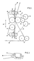
- FIG. 1 shows schematically how a pattern cylinder change can be carried out without it being necessary to switch off the printing press as before during this pattern cylinder change.
- a web of material 20 is guided over deflecting rollers 21 via a magnetic roller 22, which serves as a printing pad.
- the position of the magnetic roller 22 is fixed in the machine, so that a predetermined fabric tension is given by the rollers 21, the magnetic roller 22 and the pulling force of the web 20 during the entire operation.
- the magnetic roller is assigned two sample cylinders 23, 24, which are each arranged in print heads 25 and 26, which in turn have holders 27 and 28.
- the holder 27 together with the print head 26 or the holder 28 with the print head 25 can be moved in the plane 29, namely by the distance 37.
- the pattern cylinder 23 is in its working position, whereas the pattern cylinder 24 is is in its rest position. Ie the sample cylinder 23 rotates with the prescribed pro production speed, whereas the pattern cylinder 24 has no speed. That is, during the operation of the pattern cylinder 23, the pattern cylinder 24 can be changed in the usual manner without difficulty.
- the holders 27, 28 are moved in the plane 29 by a drive (not shown). For this purpose, one will briefly switch off the electromagnets of the magnetic roller 22, lift the sample cylinder 23 somewhat from the web 20 and then move the holder 28 upwards in FIG. At the same time, the holder 27 is also moved upward, so that the pattern cylinder 24 comes into the position above the magnetic roller 22, where it is lowered, and then the electromagnets of the magnetic roller 22 are switched on again.
- the pattern cylinders 23 and 24 it is expedient first to arrange the components arranged in their interior, e.g. Ink container, ink tube, squeegee device to lift off, on the one hand to interrupt the ink supply and on the other hand to avoid damage to the mostly thin-walled screen cylinder.
- the reverse process is then carried out, i.e. first the sample cylinder is brought into the working position and then the internal components are lowered, i.e. the ink supply is opened and the doctor blade is pressed against the sample cylinder wall.
- a repeat gear 30 is provided, which in the embodiment of FIG. 1 engages with the magnetic roller 22 and two synchronous clutches 31. Each of these two synchronous clutches is connected via a repeat shaft 35 to the drive gear 36 of the sample cylinder.
- the synchronous clutch assigned to it is actuated, whereas the sample cylinder to be brought into the rest position is uncoupled by its synchronous clutch and is then stopped automatically.
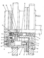
- a suitable synchronous clutch is shown in FIG.
- rappor wheels 11 are attached, which constantly rotate about the axis 1.
- the gearshift sleeve carries a gearshift claw 34, the axis 1 is also surrounded by a second hub 4, with which the gear 7 to be driven is screwed, that is, the gear which is to be synchronized with the rappor gear 11.
- the hub is mounted on the axle 1 via a ball bearing 2.
- two grooves 3 of different widths are milled axially, into which the shifting claws 34 can only latch exactly at one point without play.
- a disc 33 With the axis 1, a disc 33 is fixedly connected, and this disc is provided with two compressed air connections and a vent hole.
- An air bellows 17 is supported on the inside of the disk 33. If compressed air is applied to this air bellows 7, the force of this compressed air acts via a pressure plate 16 on the ball bearing 15, on the hub 9, which is opposed by a friction lining 8. Contact is made with the friction lining and this is pressed against the gear 7 to be driven. As a result, the acceleration of this gear wheel from zero to synchronism with the rappor wheel 11 is within less seconds.
- the disk 33 there is also a connection to a piston 12, which presses the circumferential shifting claw 34 against the hub 4 via the ball bearing 19.
- a latching of the switching claw 34 in the groove 3 is only possible at a certain point.
- the compressed air is released from the air bellows 17 via a throttle.
- the clutch begins to slip again, however, until the shifting claw 34 engages in the groove 3. That is, only the circuit with the piston 12 remains pressurized air as long as the printing process of this sample cylinder driven by the gearwheel 7 continues.
- the friction clutch 8 has only the function of a starting clutch and is always actuated briefly.
- the switching claw 34 is reset by at least two springs 13, which come into action as soon as the application of compressed air to the piston 12 is ended. Spacers 32 are provided to limit the spring travel. The springs 13 bring the piston 12 into the starting position, and there is an air gap between the friction lining 8 and the gear 7 and also between the friction lining 8 and the hub 9.
- the synchronous clutch has two main functions, namely on the one hand the acceleration of the drive of the respective printing unit from standstill to the machine speed and on the other hand a defined, repeatable engagement.
- the first is essential, as this is the only way to couple at full speed and avoid knocks and breakage, the second function is essential for the quality of the manufactured goods.
Abstract
Description
Die Erfindung betrifft eine Rundschablonen- oder Walzendruckmaschine mit mindestens zwei Druckeinheiten, von der jeweils eine in Arbeitsposition angeordnet ist, d.h. eine Maschine mit Musterzylindern.The invention relates to a circular stencil or roller printing machine with at least two printing units, one of which is arranged in the working position, i.e. a machine with sample cylinders.
Bei den bisherigen Druckmaschinen, die Rundschablonen verwenden, war es notwendig, beim Musterwechsel die Maschine abzuschalten bzw. den Druckvorgang zu unterbrechen, um den notwendigen Schablonenwechsel durchführen zu können. Dadurch geht nicht nur viel Arbeitszeit verloren, sondern es tritt auch ein höherer Materialverlust bei der zu bedruckenden Materialbahn auf, was insbesondere bei teuren Materialien Kosten verursacht.With previous printing machines that use circular stencils, it was necessary to switch off the machine or interrupt the printing process when changing the pattern in order to be able to carry out the necessary stencil change. As a result, not only is a lot of working time lost, but there is also a greater loss of material in the material web to be printed, which causes costs, particularly in the case of expensive materials.
Erfindungsgemäß wird vorgeschlagen, daß als Druckunterlage nur eine Gegenwalze oder dgl. ortsfest angeordnet ist und daß die beiden Druckeinheiten dazu relativ bewegbar angeordnet und wahlweise antreibbar sind. Die Druckunterlage ist bei Betrieb der Maschine lagefest angeordnet und es sind je zwei Druckköpfe mit je einem Musterzylinder zugeordnet, wobei die Druckköpfe an beweglichen Trägern angeordnet sein können, die über mindestens einen Antrieb gegenläufig bewegbar sind und von denen einer in Arbeitsstellung ist, wenn der andere in Ruhestellung ist. Ferner weist die Druckmaschine eine Synchronlaufkupplung auf, die jeweils einen der beiden Druckköpfe mit dem Rapportiergetriebe verbindet.According to the invention it is proposed that only a counter roller or the like is arranged in a stationary manner as a printing base and that the two printing units are arranged so as to be relatively movable and optionally drivable. The printing pad is arranged in a fixed position during operation of the machine and two print heads each with a pattern cylinder are assigned, the print heads being able to be arranged on movable supports which can be moved in opposite directions via at least one drive and one of which is in the working position when the other is at rest. Furthermore, the printing press has a synchronous clutch, which connects one of the two print heads to the repeat gear.
Dadurch werden die Nachteile des Standes der Technik vermieden. Da sich eine Druckeinheit in Druckposition und die zweite Druckeinheit in Ruheposition befindet, können die in Ruheposition befindliche Rundschablone und das Rakelsystem gewechselt werden. Will man einen Musterwechsel durchführen, so ist es nur notwendig, halb- oder vollautomatisch diesen Wechsel einzuleiten, d.h., die beiden Druckeinheiten werden gemeinsam verschwenkt oder verfahren, wobei die Druckunterlage selhst, also z.B. eine Magnetwalze, in ihrer bisherigen Lage verbleibt. Damit bleiben die Warenspannung und die Druckpaßgenauigkeit erhalten. Während des Positionswechsels der Druckeinheiten wird der aus der Arbeitsstellung entfernte Musterzylinder gestoppt und der in Arbeitsstellung gebrachte Musterzylinder wird mit Hilfe einer Synchronkupplung auf Gleichlauf gebracht und in die paßgenaue Position eingekuppelt. Zu Beginn dieses Vorganges wird die Farbzufuhr zu dem aus der Arbeitsstellung gebrachten Musterzylinder automatisch unterbrochen und die Farbzufuhr zu dem in die Arbeitsstellung gebrachten Musterzylinder wird nach Erreichen der Arbeitsstellung automatisch zugeschaltet. Durch die Überlagerung der Funktionen während des Wechselvorganges wird der Warenverlust minimiert, was die Wirtschaftlichkeit steigert.This avoids the disadvantages of the prior art. Since one printing unit is in the printing position and the second printing unit is in the rest position, the circular stencil and the squeegee system can be changed. If you want to carry out a pattern change, it is only necessary to initiate this change semi-automatically or fully automatically, ie the two printing units are pivoted or moved together, the printing pad itself, for example a magnetic roller, in its previous position remains. This maintains the fabric tension and print accuracy. During the change of position of the printing units, the sample cylinder removed from the working position is stopped and the sample cylinder brought into the working position is brought into synchronism with the aid of a synchronous clutch and is coupled into the precisely fitting position. At the beginning of this process, the ink supply to the sample cylinder brought out of the working position is automatically interrupted and the ink supply to the sample cylinder brought into the working position is automatically switched on after reaching the working position. By overlaying the functions during the changeover process, the loss of goods is minimized, which increases efficiency.
Die Erfindung wird anhand der Zeichnungen näher beschrieben. Fig.1 zeigt die Möglichkeit des Wechselvorganges schematisch dargestellt. Fig.2 zeigt einen Schnitt durch die Synchronlaufkupplung und Fig.3 gibt ein Detail dieser Kupplung wieder.The invention is described in more detail with reference to the drawings. Fig. 1 shows the possibility of the change process shown schematically. 2 shows a section through the synchronous clutch and FIG. 3 shows a detail of this clutch.
Die Fig.1 zeigt schematisch,wie ein Musterzylinderwechsel durchgeführt werden kann, ohne daß es notwendig ist, die Druckmaschine wie bisher während dieses Musterzylinderwechsels abzuschalten. Eine Warenbahn 20 wird über Umlenkwalzen 21 über eine Magnetwalze 22 geführt, die als Druckunterlage dient. Die Lage der Magnetwalze 22 ist in der Maschine fixiert, so daß während des gesamten Betriebes durch die Walzen 21, die Magentwalze 22 und die Abzugskraft der Warenbahn 20 eine vorgegebene Warenspannung gegeben wird. Der Magnetwalze sind zwei Musterzylinder 23, 24 zugeordnet, die jeweils in Druckköpfen 25 und 26 angeordnet sind, welche ihrerseits Halter 27 und 28 haben. Die Halter 27 gemeinsam mit dem Druckkopf 26 bzw. der Halter 28 mit dem Druckkopf 25 können in der Ebene 29 verschoben werden, und zwar um die Distanz 37. In Fig.1 befindet sich der Musterzylinder 23 in seiner Arbeitslage,wohingegen der Musterzylinder 24 sich in seiner Ruhestellung befindet. D.h. der Musterzylinder 23 dreht sich mit der vorgeschriebenen Pro duktions geschwindigkeit, wohingegen der Musterzylinder 24 keinerlei Geschwindigkeit aufweist. D.h.,während des Betriebes des Musterzylinders 23 kann der Musterzylinder 24 ohne Schwierigkeiten in üblicher Weise gewechselt werden. Soll nun ein Musterwechsel erfolgen, d.h., soll der Musterzylinder 24 in seine Arbeitsstellung gebracht werden, so werden durch einen nicht dargestellten Antrieb die Halter 27, 28 in der Ebene 29 verfahren. Zu diesem Zweck wird man kurzzeitig die Elektromagnete der Magnetwalze 22 abschalten, den Musterzylinder 23 etwas von der Warenbahn 20 abheben und dann in der Fig.1 den Halter 28 nach oben verfahren. Gleichzeitig wird der Halter 27 ebenfalls nach oben verfahren, so daß der Musterzylinder 24 in die Stellung oberhalb der Magnetwalze 22 kommt, wo er abgesenkt wird und dann werden die Elektromagnete der Magnetwalze 22 wieder eingeschaltet.1 shows schematically how a pattern cylinder change can be carried out without it being necessary to switch off the printing press as before during this pattern cylinder change. A web of
Es sei noch darauf hingewiesen, daß es günstig ist, beim Verfahren der Musterzylinder 23 und 24 zuerst die in ihrem Inneren angeordneten Bauteile, wie z.B. Farbbehälter, Farbrohr, Rakelvorrichtung, abzuheben, um einerseits die Farbzufuhr zu unterbrechen und andererseits Beschädigungen der meist dünnwandigen Siebzylinger zu vermeiden. Bei Inbetriebnahme eines Musterzylinders wird dann der umgekehrte Vorgang durchgeführt, d.h., zuerst wird der Musterzylinder in Arbeitsstellung gebracht und dann werden die innenliegenden Bauteile gesenkt,d.h., die Farbzufuhr wird geöffnet und die Rakel wird an die Musterzylinderwandung gepreßt.It should also be pointed out that when moving the
Bevor ein Musterzylinder 24 oder 23 in die Arbeitsstellung gebracht wird, erfolgt dessen Beschleunigung auf die Arbeitsgeschwindigkeit der Druckmaschine. Im Gleichlauf mit den anderen Elementen erfolgt in paßgenauer Position das Einkuppeln. Dies ist in Fig.1 schematisch dar gestellt. Es ist ein Rapportiergetriebe 30 vorgesehen, das bei der Ausführungsform der Fig.1 mit der Magnetwalze 22 und zwei Synchronlaufkupplungen 31 in Eingriff steht. Jede dieser beiden Synchronlaufkupplungen ist über eine Rapportwelle 35 mit dem Antriebsgetriebe 36 der Musterzylinder verbunden. Bevor der Musterzylinder in seine Arbeitsstellung gebracht wird, wird die ihm zugeordnete Synchronlaufkupplung betätigt, wohingegen der in die Ruhestellung zu verbringende Musterzylinder durch seine Synchronlaufkupplung entkuppelt wird und dann automatisch angehalten wird.Before a
In Fig.2 ist eine geeignete Synchronlaufkupplung dargestellt. Auf einer Nabe 9 sind Rapporträder 11 aufgesteckt,die sich ständig um die Achse 1 drehen. In der Nabe 9 befindet sich eine Schaltmuffe 10, die drehbar ebenfalls auf der Achse 1 mit Rollenlagern 14 gelagert ist. Die Schaltmuffe trägt eine Schaltklaue 34, die Achse 1 wird noch von einer zweiten Nabe 4 umgeben, mit der das anzutreibende Zahnrad 7 verschraubt ist, also jenes Zahnrad, das mit dem Rapportrad 11 in Gleichlauf gebracht werden soll. Die Nabe ist über ein Kugellager 2 auf der Achse 1 gelagert. An der Innenseite der Nabe 4 sind axial zwei verschieden breite Nuten 3 eingefräst, in die die Schaltklauen 34 jeweils nur an einer Stelle exakt und spielfrei einrasten können.A suitable synchronous clutch is shown in FIG. On a hub 9,
Mit der Achse 1 ist eine Scheibe 33 fest verbunden, und diese Scheibe ist mit zwei Druckluftanschlüssen sowie einer Entlüftungsbohrung versehen. An der Innenseite der Scheibe 33 stützt sich ein Luftbalg 17 ab. Wird dieser Luftbalg 7 mit Druckluft beaufschlagt, so wirkt die Kraft dieser Druckluft über eine Druckplatte 16 auf das Kugellager 15, auf die Nabe 9, der ein Reibbelag 8 gegenüberliegt. Es wird ein Kontakt mit dem Reibbelag hergestellt und dieser gegen das anzutreibende Zahnrad 7 gedrückt. Dadurch wird die Beschleunigung dieses Zahnrades von Null auf Gleichlauf mit dem Rapportrad 11 innerhalb weniger Sekunden bewirkt. In der Scheibe 33 befindet sich auch noch ein Anschluß zu einem Kolben 12, der über das Kugellager 19 die umlaufende Schaltklaue 34 gegen die Nabe 4 drückt. Eine Einrastung der Schaltklaue 34 in der Nut 3 ist aber nur an einer bestimmten Stelle möglich. Um diese Einrastung sanft und ras ch zu ermöglichen, wird die Druckluft aus dem Luftbalg 17 über eine Drossel wieder abgelassen. Dadurch beginnt die Kupplung aber wieder zu rutschen, und zwar solange bis die Schaltklaue 34 in die Nut 3 eingerastet ist. D.h., nur der Schaltkreis mit dem Kolben 12 bleibt solange druckluftbeaufschlagt, solange der Druckvorgang dieses über das Zahnrad 7 angetriebenen Musterzylinders andauert.Die Reibkupplung 8 hat nur die Funktion einer Anfahrkupplung und wird immer kurzzeitig betätigt.With the axis 1, a disc 33 is fixedly connected, and this disc is provided with two compressed air connections and a vent hole. An
Es wäre zwar auch möglich, während des Beschleunigens des Zahnrades 7, kurz bevor der Gleichlauf erreicht ist, die Schaltklaue 34 zu schalten, jedoch ist bei stark unterschiedlichen und schwankenden Betriebsbedingungen dieser Zeitpunkt mit pneumatischen Steuerungssystemen nur schwer zu erreichen.Although it would also be possible to shift the shifting
Die Rückstellung der Schaltklaue 34 wird durch mindestens zwei Federn 13 erreicht, die in Tätigkeit treten, sobald die Beaufschlagung des Kolbens 12 mit Druckluft beendet wird. Zur Begrenzung des Federweges sind Distanzschrauben 32 vorgesehen. Die Federn 13 bringen den Kolben 12 in die Ausgangsstellung, und zwischen dem Reibbelag 8 und dem Zahnrad 7 und auch zwischen dem Reibbelag 8 und der Nabe 9 ist dann ein Luftspalt gegeben.The switching
In Fig.1 ist dargelegt worden, daß die beiden Druckköpfe in einer Ebene 29 bei Wechsel der arbeitenden Schablonen entlang der Ebene 29 verfahren werden. Es ist aber selbstverständlich auch möglich, die Musterzylinder zu verschwenken, so daß dann ein Musterzylinder aus der Arbeitsstellung verschwenkt wird und der andere in die Arbeitsstellung eingeschwenkt wird. Gegebenenfalls können beide Musterzylinder an einem ge meinsamen verschwenkbaren oder verfahrbaren Halter angeordnet sein.It has been shown in FIG. 1 that the two print heads are moved in one
Die Synchronlaufkupplung hat zwei Hauptfunktionen, nämlich einerseits die Beschleunigung des Antriebes der jeweiligen Druckeinheit vom Stillstand auf die Maschinengeschwindigkeit und andererseits ein definiertes, rapportgenaues Einkuppeln. Die erste ist wesentlich, da nur so bei voller Geschwindigkeit gekuppelt werden kann, und Schläge und Bruchgefahr vermieden werden können, die zweite Funktion ist für die Qualität der hergestellten Ware wesentlich. The synchronous clutch has two main functions, namely on the one hand the acceleration of the drive of the respective printing unit from standstill to the machine speed and on the other hand a defined, repeatable engagement. The first is essential, as this is the only way to couple at full speed and avoid knocks and breakage, the second function is essential for the quality of the manufactured goods.
Claims (11)
Priority Applications (1)
| Application Number | Priority Date | Filing Date | Title |
|---|---|---|---|
| EP86115300A EP0266448A1 (en) | 1986-11-05 | 1986-11-05 | Printing machine using cylindrical screens or printing cylinders, and provided with at least two printing units |
Applications Claiming Priority (1)
| Application Number | Priority Date | Filing Date | Title |
|---|---|---|---|
| EP86115300A EP0266448A1 (en) | 1986-11-05 | 1986-11-05 | Printing machine using cylindrical screens or printing cylinders, and provided with at least two printing units |
Publications (1)
| Publication Number | Publication Date |
|---|---|
| EP0266448A1 true EP0266448A1 (en) | 1988-05-11 |
Family
ID=8195569
Family Applications (1)
| Application Number | Title | Priority Date | Filing Date |
|---|---|---|---|
| EP86115300A Withdrawn EP0266448A1 (en) | 1986-11-05 | 1986-11-05 | Printing machine using cylindrical screens or printing cylinders, and provided with at least two printing units |
Country Status (1)
| Country | Link |
|---|---|
| EP (1) | EP0266448A1 (en) |
Cited By (1)
| Publication number | Priority date | Publication date | Assignee | Title |
|---|---|---|---|---|
| GB2225286A (en) * | 1988-11-25 | 1990-05-30 | Schiavi Cesare Costr Mec | A trolley for print cylinder assemblies |
Citations (5)
| Publication number | Priority date | Publication date | Assignee | Title |
|---|---|---|---|---|
| DE537002C (en) * | 1927-05-03 | 1931-10-29 | Crabtree & Sons Ltd R | Device for printing the latest news on newspaper rotary printing machines |
| DE1937986A1 (en) * | 1968-08-02 | 1970-02-05 | Draeger Freres | Helio rotary printing press |
| GB1250921A (en) * | 1969-06-09 | 1971-10-27 | ||
| DE3313219A1 (en) * | 1983-04-13 | 1984-10-18 | Metronic Gerätebau GmbH & Co, 8702 Veitshöchheim | Printing unit for a rotary printing machine |
| NL8402665A (en) * | 1984-08-31 | 1986-03-17 | Stork Brabant Bv | Rotary screen printing machine - has separate supports for each printing station movable w.r.t main frame each with sieve cylinder and pivotable on common console |
-
1986
- 1986-11-05 EP EP86115300A patent/EP0266448A1/en not_active Withdrawn
Patent Citations (5)
| Publication number | Priority date | Publication date | Assignee | Title |
|---|---|---|---|---|
| DE537002C (en) * | 1927-05-03 | 1931-10-29 | Crabtree & Sons Ltd R | Device for printing the latest news on newspaper rotary printing machines |
| DE1937986A1 (en) * | 1968-08-02 | 1970-02-05 | Draeger Freres | Helio rotary printing press |
| GB1250921A (en) * | 1969-06-09 | 1971-10-27 | ||
| DE3313219A1 (en) * | 1983-04-13 | 1984-10-18 | Metronic Gerätebau GmbH & Co, 8702 Veitshöchheim | Printing unit for a rotary printing machine |
| NL8402665A (en) * | 1984-08-31 | 1986-03-17 | Stork Brabant Bv | Rotary screen printing machine - has separate supports for each printing station movable w.r.t main frame each with sieve cylinder and pivotable on common console |
Cited By (3)
| Publication number | Priority date | Publication date | Assignee | Title |
|---|---|---|---|---|
| GB2225286A (en) * | 1988-11-25 | 1990-05-30 | Schiavi Cesare Costr Mec | A trolley for print cylinder assemblies |
| FR2639581A1 (en) * | 1988-11-25 | 1990-06-01 | Schiavi Cesare Costr Mec | PRINTING GROUP CARRIAGE FOR A PRINTING STATION IN ROTARY MACHINES |
| GB2225286B (en) * | 1988-11-25 | 1992-04-15 | Schiavi Cesare Costr Mec | A trolley for print cylinder assemblies used in the print stations of rotary machines |
Similar Documents
| Publication | Publication Date | Title |
|---|---|---|
| DE3742129C2 (en) | ||
| EP0242661B1 (en) | Positioning device for a five-cylinder printing unit of a rotary offset printing machine | |
| DE3110468A1 (en) | DRIVE FOR FUNCTIONAL GROUPS IN ARC GUIDE CYLINDERS OF PRINTING MACHINES | |
| DE2224970A1 (en) | DEVICE FOR MOVING A WEB IN A ROTARY PRINTING MACHINE FOR PRINTING CHANGING FORMATS | |
| EP0010141B1 (en) | Device for manufacturing printed products with interchangeable imprints | |
| DE19530956A1 (en) | System for switching collector roller of folding machine between collecting and non=collecting modes | |
| DE10317283B4 (en) | Pad Printing Machine | |
| EP1138484B1 (en) | Machine for printing or decorating hollow bodies | |
| DE2642956C3 (en) | Device for setting the printing stencils in a rotary stencil printing machine | |
| DE2537919B2 (en) | Reversible folding cylinder | |
| EP0266448A1 (en) | Printing machine using cylindrical screens or printing cylinders, and provided with at least two printing units | |
| EP0424716A1 (en) | Transfer-pad printing machine with a pad cleaning device and method for operating the same | |
| DE4444189C2 (en) | Screen or screen printing machine | |
| DE2553768C3 (en) | Web-fed rotary printing press | |
| DE1902916C2 (en) | Nozzle drilling machine | |
| EP0805024A2 (en) | Rotary screen printing machine for printing large images | |
| DE3829174C2 (en) | Type wheel embossing device for producing surface embossing on objects, in particular type plates | |
| DE102007009466B4 (en) | Method for operating a flexographic printing machine and flexographic printing machine | |
| DE4312726C2 (en) | Pad Printing Machine | |
| DE4424032C1 (en) | Crepe paper mfg. device | |
| DE887321C (en) | Automatic engraving machine | |
| DE4232559C2 (en) | Device and method for registering coupling of a web-fed rotary printing press | |
| CH709824A2 (en) | Printing unit for a rotary printing machine. | |
| DE19913322A1 (en) | Plug printing machine for transferring ink from block to object has first transport device for block holder/inking device, second for plug; first and/or second transport device is linear motor | |
| WO1997037850A1 (en) | Inking-pad printing press |
Legal Events
| Date | Code | Title | Description |
|---|---|---|---|
| PUAI | Public reference made under article 153(3) epc to a published international application that has entered the european phase |
Free format text: ORIGINAL CODE: 0009012 |
|
| AK | Designated contracting states |
Kind code of ref document: A1 Designated state(s): AT CH DE FR GB IT LI NL |
|
| STAA | Information on the status of an ep patent application or granted ep patent |
Free format text: STATUS: THE APPLICATION IS DEEMED TO BE WITHDRAWN |
|
| 18D | Application deemed to be withdrawn |
Effective date: 19881112 |
|
| RIN1 | Information on inventor provided before grant (corrected) |
Inventor name: LETSCHNIG, FRIEDRICH Inventor name: MAYER, KARL |