EP0265967B1 - Vorrichtung zum Reinigen von sich drehenden Teilen von Kunststoffverarbeitungsmaschinen - Google Patents
Vorrichtung zum Reinigen von sich drehenden Teilen von Kunststoffverarbeitungsmaschinen Download PDFInfo
- Publication number
- EP0265967B1 EP0265967B1 EP87115995A EP87115995A EP0265967B1 EP 0265967 B1 EP0265967 B1 EP 0265967B1 EP 87115995 A EP87115995 A EP 87115995A EP 87115995 A EP87115995 A EP 87115995A EP 0265967 B1 EP0265967 B1 EP 0265967B1
- Authority
- EP
- European Patent Office
- Prior art keywords
- container
- clamping means
- cleaned
- tubular container
- cleaning
- Prior art date
- Legal status (The legal status is an assumption and is not a legal conclusion. Google has not performed a legal analysis and makes no representation as to the accuracy of the status listed.)
- Expired - Lifetime
Links
- 238000004140 cleaning Methods 0.000 title claims abstract description 18
- 229920003023 plastic Polymers 0.000 claims abstract description 19
- 239000004033 plastic Substances 0.000 claims abstract description 19
- 239000000843 powder Substances 0.000 claims abstract description 7
- 239000008187 granular material Substances 0.000 claims description 14
- 238000010438 heat treatment Methods 0.000 claims description 14
- 238000006073 displacement reaction Methods 0.000 claims description 3
- 238000009413 insulation Methods 0.000 claims description 3
- 230000002441 reversible effect Effects 0.000 claims description 3
- 241000237519 Bivalvia Species 0.000 claims 1
- 235000020639 clam Nutrition 0.000 claims 1
- 239000007788 liquid Substances 0.000 description 5
- 238000003780 insertion Methods 0.000 description 4
- 230000037431 insertion Effects 0.000 description 4
- 238000000354 decomposition reaction Methods 0.000 description 2
- 229910052500 inorganic mineral Inorganic materials 0.000 description 2
- 238000002844 melting Methods 0.000 description 2
- 230000008018 melting Effects 0.000 description 2
- 238000000034 method Methods 0.000 description 2
- 239000011707 mineral Substances 0.000 description 2
- 239000000203 mixture Substances 0.000 description 2
- 229910000831 Steel Inorganic materials 0.000 description 1
- 238000005299 abrasion Methods 0.000 description 1
- 230000015572 biosynthetic process Effects 0.000 description 1
- 239000000969 carrier Substances 0.000 description 1
- 239000011248 coating agent Substances 0.000 description 1
- 238000000576 coating method Methods 0.000 description 1
- 238000011109 contamination Methods 0.000 description 1
- 239000002826 coolant Substances 0.000 description 1
- 230000001419 dependent effect Effects 0.000 description 1
- 230000000694 effects Effects 0.000 description 1
- 238000007654 immersion Methods 0.000 description 1
- 238000010102 injection blow moulding Methods 0.000 description 1
- 238000001746 injection moulding Methods 0.000 description 1
- 239000011490 mineral wool Substances 0.000 description 1
- 239000004570 mortar (masonry) Substances 0.000 description 1
- 230000010355 oscillation Effects 0.000 description 1
- 239000011505 plaster Substances 0.000 description 1
- 239000008262 pumice Substances 0.000 description 1
- 238000007790 scraping Methods 0.000 description 1
- 229910001220 stainless steel Inorganic materials 0.000 description 1
- 239000010935 stainless steel Substances 0.000 description 1
- 239000010959 steel Substances 0.000 description 1
- 230000004936 stimulating effect Effects 0.000 description 1
- 239000004575 stone Substances 0.000 description 1
Images
Classifications
-
- B—PERFORMING OPERATIONS; TRANSPORTING
- B08—CLEANING
- B08B—CLEANING IN GENERAL; PREVENTION OF FOULING IN GENERAL
- B08B7/00—Cleaning by methods not provided for in a single other subclass or a single group in this subclass
- B08B7/0064—Cleaning by methods not provided for in a single other subclass or a single group in this subclass by temperature changes
- B08B7/0071—Cleaning by methods not provided for in a single other subclass or a single group in this subclass by temperature changes by heating
-
- B—PERFORMING OPERATIONS; TRANSPORTING
- B29—WORKING OF PLASTICS; WORKING OF SUBSTANCES IN A PLASTIC STATE IN GENERAL
- B29C—SHAPING OR JOINING OF PLASTICS; SHAPING OF MATERIAL IN A PLASTIC STATE, NOT OTHERWISE PROVIDED FOR; AFTER-TREATMENT OF THE SHAPED PRODUCTS, e.g. REPAIRING
- B29C48/00—Extrusion moulding, i.e. expressing the moulding material through a die or nozzle which imparts the desired form; Apparatus therefor
- B29C48/25—Component parts, details or accessories; Auxiliary operations
- B29C48/256—Exchangeable extruder parts
- B29C48/2561—Mounting or handling of the screw
-
- B—PERFORMING OPERATIONS; TRANSPORTING
- B29—WORKING OF PLASTICS; WORKING OF SUBSTANCES IN A PLASTIC STATE IN GENERAL
- B29C—SHAPING OR JOINING OF PLASTICS; SHAPING OF MATERIAL IN A PLASTIC STATE, NOT OTHERWISE PROVIDED FOR; AFTER-TREATMENT OF THE SHAPED PRODUCTS, e.g. REPAIRING
- B29C48/00—Extrusion moulding, i.e. expressing the moulding material through a die or nozzle which imparts the desired form; Apparatus therefor
- B29C48/25—Component parts, details or accessories; Auxiliary operations
- B29C48/27—Cleaning; Purging; Avoiding contamination
-
- B—PERFORMING OPERATIONS; TRANSPORTING
- B29—WORKING OF PLASTICS; WORKING OF SUBSTANCES IN A PLASTIC STATE IN GENERAL
- B29C—SHAPING OR JOINING OF PLASTICS; SHAPING OF MATERIAL IN A PLASTIC STATE, NOT OTHERWISE PROVIDED FOR; AFTER-TREATMENT OF THE SHAPED PRODUCTS, e.g. REPAIRING
- B29C48/00—Extrusion moulding, i.e. expressing the moulding material through a die or nozzle which imparts the desired form; Apparatus therefor
- B29C48/03—Extrusion moulding, i.e. expressing the moulding material through a die or nozzle which imparts the desired form; Apparatus therefor characterised by the shape of the extruded material at extrusion
Definitions
- the invention relates to a device of the type specified in the preamble of claim 1.
- a device is known from DE-C-3309878.
- DE-C-31 46 478 a cleaning device is known which avoids this disadvantage and the formation of harmful plastic decomposition products.
- This device consists of a closed, heatable container filled with a non-aggressive cleaning liquid, into which the relevant parts are inserted. The cleaning effect is achieved by heating the liquid to or just above the melting point of the plastic in question and at the same time stimulating an oscillation movement in the liquid.
- DE-C-33 09 878 discloses a device which operates essentially on the same principle, but which is specifically designed for cleaning bulky parts such as extruder screws. However, the device takes up a relatively large amount of space and has a high electrical connection value Supply of the necessary powerful heating, possibly also requires a coolant connection and, above all, requires a long cycle time due to the thermal inertia of the cleaning liquid.
- the invention has for its object to provide a cleaning device especially for rotating parts of plastic processing machines that has a simpler structure, requires little space and a faster cycle time while maintaining the advantages of the two known devices described, namely low-wear and exhaust-free cleaning allowed.
- rotating parts of plastic processing machines can also be "dry" completely free of adhering plastic residues, provided that these parts are slowly immersed in a powder or granulate, which is placed on the respective plastic, while not rotating too quickly Temperature heated and selected according to grain size and abrasiveness so that the surface coating of the parts in question does not suffer. Since the inner diameter of the tubular container for receiving the part to be cleaned must be only slightly larger than the largest diameter of the part to be cleaned and - in contrast to the device known from DE-PS 33 09 878 - does not have to be tilted or pivoted the space requirement of the device proposed here is low.
- the powder or granulate used has a relatively small heat capacity and the part can be moved out of the tubular container immediately after cleaning, it is reduced the cycle time considerably.
- handling the powder or granulate, usually a mineral or mineral mixture is considerably less problematic than using a special cleaning liquid.
- the tubular container is standing and the tensioning device is arranged above it. In this way, the filling of the tubular container with the powder or granulate and the emptying of the same is very simple.
- the heating of the container best consists of an electrical heating device surrounding it, which in turn is surrounded by thermal insulation.
- the heating device can have the form of a further tube concentrically surrounding the tubular container, in which a heating coil is embedded in an insulated manner.
- the rotary drive of the tensioning device best consists of a reversible electric motor with worm gear. If the parts to be cleaned are extruder screws, the electric motor turns them according to the screw pitch during insertion and until the end of the cleaning process in one direction of rotation, but for easier removal in the other direction.
- a double-acting piston / cylinder unit is expedient as a displacement device for the tensioning device.
- a threaded spindle would serve the same purpose.
- the tubular container has a funnel-shaped insertion opening for the part to be cleaned. It has been shown that the plastic residues removed from the part to be cleaned or cleaned accumulate at least for the most part in the region of the insertion opening of the tubular container.
- the funnel-shaped design of the insertion opening creates a sufficient holding volume for these plastic residues and enables their convenient removal.
- the powder or granulate that forms the filling of the tubular container is also subject to a certain amount of wear, it must be replaced from time to time. This exchange can be accomplished particularly easily if the container bottom consists of a slide, below which a collecting container is arranged. In addition, it can be provided that the part of the slide forming the container bottom in the closed position has a sieve shape if the filling of the container consists of granules. Dust-like abrasion is then continuously removed into the collecting container during the cleaning cycle.
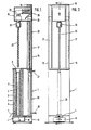
- the device shown in the drawing consists of a box-shaped base 1 made of sheet steel, in which there is a tubular container 2 with a funnel-shaped upper opening 3.
- the lower opening of the container 2 is closed by a slide 4.
- the tubular container 2 and the slide 4 are preferably made of stainless steel.
- the tubular container 2 is enclosed by a heating tube 5, in which a heating coil 6 is embedded, which is connected via the indicated cable 7 to a control cabinet, not shown.
- the container 2 is filled up to a height dependent on the volume of the workpiece to be cleaned with a slightly abrasive, sufficiently heat-resistant granulate.
- a slightly abrasive, sufficiently heat-resistant granulate As an example, a mixture of granules made of hardened plaster and hardened mortar or pumice stone granules, each with an average grain size of approx. 0.5 mm to approx. 4 mm, can be mentioned.
- This granulate can be emptied into a collecting container 10 arranged below it via the slide 4. Dust-like portions of the granules 9 can, however, also reach the collecting container 10 in the drawn closed position of the slide 4 via its sieve-like perforated part 4a.
- a small pressure medium cylinder 11 is provided, with the aid of which the slide 4 is displaced at least a small distance in the direction of the open position. If desired, the slide can then be moved from the front, i.e. from the left in Figure 1, completely pulled out by hand.
- each of the carriers 15 contains a guide column or a guide tube 17.
- a head 19 runs over guide bushings 18.
- the head 19 contains a reversible electric motor 20 with a connecting cable 21, downstream worm gear 22 and a chuck 23 into which one end of a extruder screw 24 to be cleaned is clamped (not shown in FIG. 2).
- the head 19 connects the end of a piston rod 25 of a double-acting piston / cylinder unit 26 which is installed in the lower part 1.
- the piston / cylinder unit 26 with the indicated pressure medium connections 27 and 28 makes it possible to move the head 19 up and down along the guide columns 17.
- the device works as follows, the individual functions being controlled via the control cabinet (not shown), which can, however, be integrated, for example, in the lower part 1:
- the heating (heating pipe 5) is switched on.
- the electric motor 20 is switched on in a direction of rotation corresponding to the slope of the screw line of the extruder screw 24.
- the worm gear 22 reduces the speed of the electric motor 20 to, for example, 40 to 60 rpm.
- the piston / cylinder unit 26 is pressurized via the connection 27 so that the head 19 slowly lowers, for example at a speed of 1 m / min.
- the lowering movement of the head 19 comes to a standstill while the chuck 23 continues to rotate the extruder screw 24.
- the direction of rotation of the electric motor 20 reverses.
- the piston / cylinder unit 26 is pressurized via the port 28 with pressure medium, so that the head slowly moves upwards again until it reaches its upper end position.
- the heating is switched off. This completes the cleaning cycle.
- the temperature up to which the granulate 9 is heated depends on the type of plastic to be removed.
- the following can be given as examples:
- the respective temperatures should not be exceeded in order to avoid decomposition of the plastic.
- the set temperature does not necessarily have to reach the melting point of the respective plastic.
- the duration of the actual cleaning process depends within certain limits on the profile shape, the thickness and the degree of contamination of the workpiece in question. It takes about 10 minutes to free an extruder screw with a diameter of 20 mm that is hard glued with PVC.
Landscapes
- Engineering & Computer Science (AREA)
- Mechanical Engineering (AREA)
- Processing And Handling Of Plastics And Other Materials For Molding In General (AREA)
- Separation, Recovery Or Treatment Of Waste Materials Containing Plastics (AREA)
- Extrusion Moulding Of Plastics Or The Like (AREA)
- Cleaning In General (AREA)
- Injection Moulding Of Plastics Or The Like (AREA)
- Cleaning By Liquid Or Steam (AREA)
Priority Applications (1)
| Application Number | Priority Date | Filing Date | Title |
|---|---|---|---|
| AT87115995T ATE61278T1 (de) | 1986-10-31 | 1987-10-30 | Vorrichtung zum reinigen von sich drehenden teilen von kunststoffverarbeitungsmaschinen. |
Applications Claiming Priority (2)
| Application Number | Priority Date | Filing Date | Title |
|---|---|---|---|
| DE3637070 | 1986-10-31 | ||
| DE19863637070 DE3637070A1 (de) | 1986-10-31 | 1986-10-31 | Vorrichtung zum reinigen von sich drehenden teilen von kunststoffverarbeitungsmaschinen |
Publications (3)
| Publication Number | Publication Date |
|---|---|
| EP0265967A2 EP0265967A2 (de) | 1988-05-04 |
| EP0265967A3 EP0265967A3 (en) | 1989-07-26 |
| EP0265967B1 true EP0265967B1 (de) | 1991-03-06 |
Family
ID=6312860
Family Applications (1)
| Application Number | Title | Priority Date | Filing Date |
|---|---|---|---|
| EP87115995A Expired - Lifetime EP0265967B1 (de) | 1986-10-31 | 1987-10-30 | Vorrichtung zum Reinigen von sich drehenden Teilen von Kunststoffverarbeitungsmaschinen |
Country Status (6)
| Country | Link |
|---|---|
| US (1) | US4848379A (https=) |
| EP (1) | EP0265967B1 (https=) |
| JP (1) | JPS63159025A (https=) |
| AT (1) | ATE61278T1 (https=) |
| CA (1) | CA1284257C (https=) |
| DE (1) | DE3637070A1 (https=) |
Families Citing this family (15)
| Publication number | Priority date | Publication date | Assignee | Title |
|---|---|---|---|---|
| NL9200323A (nl) * | 1992-02-21 | 1993-09-16 | Handelsonderneming H Swanenber | Werkwijze en inrichting voor het verwijderen van bitumen van buizen of pijpen. |
| DE4214976A1 (de) * | 1992-05-06 | 1993-11-11 | Ver Foerderung Inst Kunststoff | Verfahren und Vorrichtung zur Montage und Demontage von Extrusionsmaschinen mit hohler Schnecke |
| DE4302415C1 (de) * | 1993-01-28 | 1993-12-09 | Christ Caroline | Verfahren und Vorrichtung zum Reinigen von Teilen von Kunststoffverarbeitungsmaschinen |
| CN101973119B (zh) * | 2010-10-22 | 2012-11-28 | 张家港市兰航机械有限公司 | 过滤挤出机的清理装置 |
| JP5634970B2 (ja) * | 2011-10-25 | 2014-12-03 | 世紀株式会社 | 樹脂成形機のバルブスリーブ回転による色替え装置 |
| CN103464425B (zh) * | 2013-09-26 | 2015-09-30 | 天津金发新材料有限公司 | 一种螺杆自动清洗器 |
| CN103465437B (zh) * | 2013-09-26 | 2015-09-30 | 天津金发新材料有限公司 | 一种螺杆自动清洗装置 |
| CN104028483B (zh) * | 2014-05-29 | 2015-11-18 | 昆山中士设备工业有限公司 | 一种螺杆清洗器 |
| CN104028515B (zh) * | 2014-05-29 | 2016-08-24 | 昆山中士设备工业有限公司 | 一种螺杆清洗装置 |
| CN104028516A (zh) * | 2014-05-30 | 2014-09-10 | 昆山中士设备工业有限公司 | 一种螺杆清洗设备 |
| CN104841653A (zh) * | 2015-05-18 | 2015-08-19 | 重庆三峡学院 | 一种螺杆洗丝机 |
| CN108031680A (zh) * | 2017-12-28 | 2018-05-15 | 安徽盼盼食品有限公司 | 一种巧克力搅拌机清洗装置 |
| CN110076110A (zh) * | 2019-05-28 | 2019-08-02 | 中铁建工集团有限公司 | 一种螺杆清洗机 |
| CN112553781B (zh) * | 2020-11-03 | 2022-07-29 | 广西德福莱医疗器械有限公司 | 熔喷布挤出方法 |
| CN113799358B (zh) * | 2021-11-03 | 2024-08-30 | 上海稳羿科技有限公司 | 模具清洗机 |
Family Cites Families (9)
| Publication number | Priority date | Publication date | Assignee | Title |
|---|---|---|---|---|
| US3071458A (en) * | 1960-05-09 | 1963-01-01 | Finkl & Sons Co | Method of adding charge material to molten metal under vacuum |
| US3071498A (en) * | 1960-11-09 | 1963-01-01 | Western Electric Co | Methods of and compositions for cleaning plastics extruders |
| FR2174684A1 (en) * | 1972-03-07 | 1973-10-19 | Creusot Loire | Extrusion machine - with internal barrel section haul off for exposing the screw |
| DD111518A3 (https=) * | 1972-05-25 | 1975-02-20 | ||
| US4004787A (en) * | 1975-01-10 | 1977-01-25 | Usm Corporation | Mixing and venting extruder |
| US4244072A (en) * | 1979-07-30 | 1981-01-13 | Dunham Heyward O | Metal tube cleaning apparatus |
| DE3146478C2 (de) * | 1981-11-24 | 1986-07-24 | Caroline Christ Fabrikation chemischer Erzeugnisse, 8060 Dachau | Vorrichtung zum Reinigen von Spritzdüsen, Förderschnecken und dergl. Teilen von Kunststoffspritzgießmaschinen von anhaftenden Resten thermoplastischer Kunststoffe |
| DE3309878C1 (de) * | 1983-03-18 | 1984-06-14 | Caroline Christ Fabrikation chemischer Erzeugnisse, 8060 Dachau | Vorrichtung zum Reinigen solcher Teile von Kunststoffverarbeitungsmaschinen,an denen Kunststoffreste anhaften |
| DE3611113C1 (de) * | 1986-04-03 | 1987-07-23 | Werner & Pfleiderer | Abziehvorrichtung fuer Schneckenelemente |
-
1986
- 1986-10-31 DE DE19863637070 patent/DE3637070A1/de active Granted
-
1987
- 1987-10-26 US US07/113,463 patent/US4848379A/en not_active Expired - Fee Related
- 1987-10-30 CA CA000550722A patent/CA1284257C/en not_active Expired - Lifetime
- 1987-10-30 EP EP87115995A patent/EP0265967B1/de not_active Expired - Lifetime
- 1987-10-30 AT AT87115995T patent/ATE61278T1/de not_active IP Right Cessation
- 1987-10-30 JP JP62273628A patent/JPS63159025A/ja active Pending
Also Published As
| Publication number | Publication date |
|---|---|
| DE3637070A1 (de) | 1988-05-11 |
| EP0265967A2 (de) | 1988-05-04 |
| ATE61278T1 (de) | 1991-03-15 |
| CA1284257C (en) | 1991-05-21 |
| DE3637070C2 (https=) | 1988-12-15 |
| JPS63159025A (ja) | 1988-07-01 |
| EP0265967A3 (en) | 1989-07-26 |
| US4848379A (en) | 1989-07-18 |
Similar Documents
| Publication | Publication Date | Title |
|---|---|---|
| EP0265967B1 (de) | Vorrichtung zum Reinigen von sich drehenden Teilen von Kunststoffverarbeitungsmaschinen | |
| DE7813501U1 (de) | Vorrichtung zum portionieren von teig | |
| DE3126257A1 (de) | Rundschleifmaschine | |
| DE2626938A1 (de) | Temperaturmessvorrichtung fuer drehrohroefen | |
| DE3146478C2 (de) | Vorrichtung zum Reinigen von Spritzdüsen, Förderschnecken und dergl. Teilen von Kunststoffspritzgießmaschinen von anhaftenden Resten thermoplastischer Kunststoffe | |
| EP0981501B1 (de) | Verfahren und vorrichtung zur herstellung einer homogenen, schlierenfreien quarzglasplatte | |
| DE2754636A1 (de) | Reinigungsvorrichtung fuer werkzeugspannkegel | |
| EP0693685A1 (de) | Vorrichtung zum Bestimmen des Stickstoff- und Proteingehalts, insbesondere von Lebensmitteln | |
| AT525965B1 (de) | Vorrichtung für einen mit Kaffeepulver befüllbaren Siebträger | |
| DE10157970A1 (de) | Mischer mit einer Vorrichtung zur Reinigung desselben | |
| DE2914419C2 (de) | Einrichtung zum Reinigen der Dichtungsflächen der Planiertüren und Planierlochrahmen von Horizontalkammer-Verkokungsöfen | |
| EP0368035B1 (de) | Vorrichtung zur diskontinuierlichen Entschlammung von Salzbädern | |
| DE2212055C3 (de) | Vorrichtung zum Verschweißen von koaxial liegenden Rohren aus thermoplastischem Kunststoff | |
| DE2316468C3 (de) | Maschine zum Ziehen von Zuckermasse zu Fäden | |
| DE2604983C3 (de) | Zuckerziehmaschine | |
| DE1519897C3 (https=) | ||
| DE29505567U1 (de) | Vorrichtung zum Verschließen von Gefäßen mit Schraubkappen | |
| DE1132704B (de) | Vorrichtung zum Angeben von Leim an stirnseitig bearbeitete, profilierte, z. B. gezinkte Werkstuecke aus Holz od. dgl. | |
| AT413087B (de) | Vorrichtung zum bearbeiten von holzstäben oder holzsäulen | |
| CH467010A (de) | Gerät zum Reinigen von Kesseln | |
| DE10223855B4 (de) | Vorrichtung zum Aufbau eines Sootkörpers | |
| AT124377B (de) | Verfahren und Maschine zur Herstellung von Glasröhren oder -stäben durch Ziehen. | |
| DE1245546C2 (de) | Vorrichtung zum Zusammenschmelzen zweier Glashohlkoerperteile | |
| DE2431626A1 (de) | Reinigungsvorrichtung fuer maschinenteile | |
| DE948980C (de) | Verfahren und Vorrichtung zum serienmaessigen Oberflaechenhaerten von Werkstuecken mit Hilfe der Autogenflamme |
Legal Events
| Date | Code | Title | Description |
|---|---|---|---|
| PUAI | Public reference made under article 153(3) epc to a published international application that has entered the european phase |
Free format text: ORIGINAL CODE: 0009012 |
|
| AK | Designated contracting states |
Kind code of ref document: A2 Designated state(s): AT BE CH FR GB IT LI NL SE |
|
| 17P | Request for examination filed |
Effective date: 19890321 |
|
| PUAL | Search report despatched |
Free format text: ORIGINAL CODE: 0009013 |
|
| AK | Designated contracting states |
Kind code of ref document: A3 Designated state(s): AT BE CH FR GB IT LI NL SE |
|
| 17Q | First examination report despatched |
Effective date: 19900801 |
|
| GRAA | (expected) grant |
Free format text: ORIGINAL CODE: 0009210 |
|
| AK | Designated contracting states |
Kind code of ref document: B1 Designated state(s): AT BE CH FR GB IT LI NL SE |
|
| REF | Corresponds to: |
Ref document number: 61278 Country of ref document: AT Date of ref document: 19910315 Kind code of ref document: T |
|
| ITF | It: translation for a ep patent filed | ||
| ET | Fr: translation filed | ||
| GBT | Gb: translation of ep patent filed (gb section 77(6)(a)/1977) | ||
| PGFP | Annual fee paid to national office [announced via postgrant information from national office to epo] |
Ref country code: SE Payment date: 19911018 Year of fee payment: 5 |
|
| PGFP | Annual fee paid to national office [announced via postgrant information from national office to epo] |
Ref country code: BE Payment date: 19911024 Year of fee payment: 5 |
|
| PGFP | Annual fee paid to national office [announced via postgrant information from national office to epo] |
Ref country code: AT Payment date: 19911028 Year of fee payment: 5 |
|
| PGFP | Annual fee paid to national office [announced via postgrant information from national office to epo] |
Ref country code: GB Payment date: 19911029 Year of fee payment: 5 |
|
| PGFP | Annual fee paid to national office [announced via postgrant information from national office to epo] |
Ref country code: FR Payment date: 19911030 Year of fee payment: 5 |
|
| PGFP | Annual fee paid to national office [announced via postgrant information from national office to epo] |
Ref country code: NL Payment date: 19911031 Year of fee payment: 5 |
|
| PGFP | Annual fee paid to national office [announced via postgrant information from national office to epo] |
Ref country code: CH Payment date: 19911114 Year of fee payment: 5 |
|
| PLBE | No opposition filed within time limit |
Free format text: ORIGINAL CODE: 0009261 |
|
| STAA | Information on the status of an ep patent application or granted ep patent |
Free format text: STATUS: NO OPPOSITION FILED WITHIN TIME LIMIT |
|
| 26N | No opposition filed | ||
| PG25 | Lapsed in a contracting state [announced via postgrant information from national office to epo] |
Ref country code: GB Effective date: 19921030 Ref country code: AT Effective date: 19921030 |
|
| PG25 | Lapsed in a contracting state [announced via postgrant information from national office to epo] |
Ref country code: SE Effective date: 19921031 Ref country code: LI Effective date: 19921031 Ref country code: CH Effective date: 19921031 Ref country code: BE Effective date: 19921031 |
|
| BERE | Be: lapsed |
Owner name: CAROLINE CHRIST ABGASFREIE WERKZEUGREINIGUNGSAPPA Effective date: 19921031 |
|
| PG25 | Lapsed in a contracting state [announced via postgrant information from national office to epo] |
Ref country code: NL Effective date: 19930501 |
|
| NLV4 | Nl: lapsed or anulled due to non-payment of the annual fee | ||
| GBPC | Gb: european patent ceased through non-payment of renewal fee |
Effective date: 19921030 |
|
| PG25 | Lapsed in a contracting state [announced via postgrant information from national office to epo] |
Ref country code: FR Effective date: 19930630 |
|
| REG | Reference to a national code |
Ref country code: CH Ref legal event code: PL |
|
| REG | Reference to a national code |
Ref country code: FR Ref legal event code: ST |
|
| EUG | Se: european patent has lapsed |
Ref document number: 87115995.0 Effective date: 19930510 |
|
| PG25 | Lapsed in a contracting state [announced via postgrant information from national office to epo] |
Ref country code: IT Free format text: LAPSE BECAUSE OF NON-PAYMENT OF DUE FEES;WARNING: LAPSES OF ITALIAN PATENTS WITH EFFECTIVE DATE BEFORE 2007 MAY HAVE OCCURRED AT ANY TIME BEFORE 2007. THE CORRECT EFFECTIVE DATE MAY BE DIFFERENT FROM THE ONE RECORDED. Effective date: 20051030 |