EP0264923B1 - Doppelzylinderschloss - Google Patents
Doppelzylinderschloss Download PDFInfo
- Publication number
- EP0264923B1 EP0264923B1 EP87115376A EP87115376A EP0264923B1 EP 0264923 B1 EP0264923 B1 EP 0264923B1 EP 87115376 A EP87115376 A EP 87115376A EP 87115376 A EP87115376 A EP 87115376A EP 0264923 B1 EP0264923 B1 EP 0264923B1
- Authority
- EP
- European Patent Office
- Prior art keywords
- spring
- coupling
- key
- pressure
- collar
- Prior art date
- Legal status (The legal status is an assumption and is not a legal conclusion. Google has not performed a legal analysis and makes no representation as to the accuracy of the status listed.)
- Expired - Lifetime
Links
Images


Classifications
-
- E—FIXED CONSTRUCTIONS
- E05—LOCKS; KEYS; WINDOW OR DOOR FITTINGS; SAFES
- E05B—LOCKS; ACCESSORIES THEREFOR; HANDCUFFS
- E05B9/00—Lock casings or latch-mechanism casings ; Fastening locks or fasteners or parts thereof to the wing
- E05B9/10—Coupling devices for the two halves of double cylinder locks, e.g. devices for coupling the rotor with the locking cam
- E05B9/105—Coupling devices for the two halves of double cylinder locks, e.g. devices for coupling the rotor with the locking cam including disengagement means, e.g. opening from one side being still possible even if the key is inserted from the other side
Definitions
- the invention relates to a double cylinder lock according to the preamble of claim 1 and 2 respectively.
- a double cylinder lock is known in which the clutch consists of a coupling ring which can be brought into engagement with one or the other cylinder by a (resiliently) displaceable sliding part.
- Another multi-part clutch is known for example from DE-GM 19 45 884.
- Couplings consisting of several parts are complex and expensive to produce and, moreover, the possible uses and applications are limited. Locking on both sides with the key inserted is only possible, for example, using a special hazard key.
- a coupling with the features in the preamble of claim 1 or 2 is known from DE 30 24 073 A1 and AT-B322 401.
- the structure of both versions is very simple.
- the invention is therefore based on the object of designing the double cylinder lock of the type mentioned at the outset in such a way that inexpensive manufacture is possible and that the possible uses and uses can be expanded by small changes.
- the special advantage - apart from the simple manufacture - in the double cylinder lock according to the invention is that the lock can be opened from the other side of the lock even when the key is inserted or - after a simple conversion - such an opening is impossible, at least with a normal key (without a hazard code). With this conversion, only the spring is replaced by a non-elastic element.
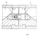
- the right lock cylinder is designated 1 and the left lock cylinder 2.
- the lock bit 3 has recesses 4 into which elastic spring legs 5, which are deformed by the inserted key 6, can be pressed. In this state, the respective lock cylinder is then coupled to the lock bit 3, i.e. a closing movement can be carried out when the key 6 is turned.
- the spring legs 5 are parts of the coupling itself. This coupling consists of stops 7 for the key tip. The spring legs 5 are firmly connected on one side to these stops. The two stops 7 form the coupling parts 7.1 and 7.2 and they are connected by a bolt arrangement 8.
- this bolt arrangement 8 consists of a bolt 8.1 which is firmly connected to the one coupling part 7.1 and which can penetrate into a bore 8.2 of the axially opposite coupling part 7.2.
- the mobility is limited by a spring 9.
- the coupling can be actuated by the inserted "normal" key 6.1, ie the second spring leg can also be pressed into the recess 4 of the locking bit 3 because the distance between the coupling parts 7.1 and 7.2 can be combined.
- a hotel or bathroom door can be opened from the outside, even if the door is locked from the inside and the key is in the key.
- the stops are also denoted by 7 in FIG. 3 and the spring legs by 5.
- the spring legs 5 are not fastened to the stops, but instead sit in the form of spring windings on the bolts 13, 14, which are extensions of the stops 7 are trained.
- the axial lengths of the bolts 13, 14 are dimensioned such that the total length is less than the maximum possible distance between the stops.
- the spring turns extend beyond the bolt ends and are separated by an intermediate plate 15.
- this lock can only be opened by means of a hazard key if a key is on the opposite side.
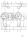
- the coupling consists of a pressure sleeve 13 and a pressure pin 14, the pressure pin being mounted coaxially in the pressure sleeve, and the pressure sleeve and pressure pin are pressed apart by a pressure spring 16, with a stop 19 being provided for limitation.
- a pressure spring 16 At the ends of the pressure sleeve or the pressure pin facing away from each other there are locking levers 17, 17 'which are pivotably mounted (pivot axis 15).
- the force of the spring 16 acts not only between the pressure sleeve 13 and the pressure pin 14, but also between the locking levers 17, 17 'on which the spring is supported.
- the locking levers 17, 17 ' are designed or pivoted so that they are set at an angle of 90 to the lock axis.
- the force of the spring 16 causes the pressure pin 14, as previously indicated, to be pushed away from the pressure sleeve 13, and thus - due to the predetermined length of the coupling - the locking lever then engages with the locking bar groove when no key is in the lock is inserted. If, as can be seen from the drawing, a key 12 is inserted, in this case the pressure pin 14 is axially displaced and the latching lever 17 can come into engagement with the lock bit groove 4, so that in this way the lock bit is coupled to the core 1 in a rotationally secure manner and a closing process can be triggered. If a second key is now inserted from the opposite side (this is not shown in the drawing), this causes the pressure sleeve 13 and the pressure pin 14 to be pushed together. If the core has not been in the pull-off position, the locking lever 17 is deflected and tilts around it Bearing pin 15.
Description
- Die Erfindung betrifft ein Doppelzylinderschloß gemäß dem Oberbegriff des Patentanspruchs 1 bzw. 2.
- Aus der DE-OS 15 53 535 ist ein Doppelzylinderschloß bekannt, bei dem die Kupplung aus einem Kupplungsring besteht, der durch ein (federnd) gelagertes Verschiebeteil jeweils mit dem einen oder anderen Zylinder in Eingriff gebracht werden kann.
- Eine weitere mehrteillge Kupplung ist beispielsweise aus dem DE-GM 19 45 884 bekannt.
- Aus mehreren Teilen bestehende Kupplungen sind in der Herstellung aufwendig und teuer und darüberhinaus sind die Anwendungs- und Einsatzmöglichkeiten eingeschränkt. Ein beidseitiges Schließen bei steckendem Schlüssel ist z.B. nur unter Verwendung eines besonderen Gefahrenschlüssels möglich.
- Eine Kupplung mit den Merkmalen im Oberbegriff des Anspruchs 1 bzw. 2 ist aus der DE 30 24 073 A 1 sowie der AT-B322 401 bekannt. Beide Ausführungen sind vom Aufbau her sehr einfach.
- Der Erfindung liegt daher die Aufgabe zugrunde, das Doppelzylinderschloß der eingangs genannten Art so auszubilden, daß eine preisgünstige Herstellung möglich ist und daß durch geringe Veränderungen die Anwendungs-und Einsatzmöglichkeiten erweiterbar sind.
- Gelöst wird diese Aufgabe erfindungsgemäß mit den Merkmalen im Kennzeichen des Patentanspruchs 1.
- Vorzugsweise Ausgestaltungen ergeben sich aus den Unteransprüchen.
- Der besondere Vorteil - abgesehen von der einfachen Herstellung - liegt bei dem erfindungsgemäßen Doppelzylinderschloß darin, daß das Schloß auch bei steckendem Schlüssel von der anderen Schloßseite geöffnet werden kann oder aber - nach einfachem Umbau - ein derartiges Öffnen ausgeschlossen ist, jedenfalls mit einem normalen Schlüssel (also ohne Gefahrenschlüssel). Bei diesem Umbau wird lediglich die Feder durch ein nicht elastisches Element ersetzt.
- Die Erfindung soll nachfolgend anhand von Ausführungsbeispielen in den Zeichnungen erläutert werden.
- Dabei zeigt:
- Fig. 1
- eine Ausführung der erfindungsgemäßen Kupplung mit durch ein Federelement verbundenen Kupplungsteilen und mit einseitig eingeführtem Schlüssel,
- Fig. 2
- beidseitig eingeführte Schlüssel bei der Kupplung nach Fig. 1,
- Fig. 3
- eine weitere Ausführungsform der Kupplung und
- Fig. 4
- eine weitere Ausführungsform der Kupplung.
- In allen Figuren ist der rechte Schließzylinder mit 1 und der linke Schließzylinder mit 2 bezeichnet.
- Der Schließbart 3 weist Ausnehmungen 4 auf, in die elastische Federschenkel 5, die durch den eingeführten Schlüssel 6 verformt werden, eindrückbar sind. In diesem Zustand ist dann der jeweilige Schließzylinder mit dem Schließbart 3 gekoppelt, d.h. es kann eine Schließbewegung bei Drehung des Schlüssels 6 ausgeführt werden.
- Die Federschenkel 5 sind Teile der Kupplung selbst. Diese Kupplung besteht aus Anschlägen 7 für die Schlüsselspitze. Die Federschenkel 5 sind einseitig mit diesen Anschlägen fest verbunden. Die beiden Anschläge 7 bilden die Kupplungsteile 7.1 und 7.2 und sie sind durch eine Bolzenanordnung 8 verbunden.
- Nach Fig. 1 besteht diese Bolzenanordnung 8 aus einem mit dem einen Kupplungsteil 7.1 fest verbundenen Bolzen 8.1, der in eine Bohrung 8.2 des axial gegenüberliegenden Kupplungsteiles 7.2 eindringen kann. Die Beweglichkeit wird durch eine Feder 9 begrenzt. Wie sich aus der Fig. 2 ergibt, kann auch bei steckendem Schlüssel 6 durch den eingeführten "normalen" Schlüssel 6.1 die Kupplung betätigt werden, d.h. auch der zweite Federschenkel kann in die Ausnehmung 4 des Schließbartes 3 gedrückt werden, weil sich der Abstand der Kupplungsteile 7.1 und 7.2 vereinigen läßt. Damit ist im Gefahrenfall beispielsweise eine Hotel- oder Badezimmertür von außen zu öffnen, auch wenn die Tür von innen verschlossen ist und der Schlüssel steckt.
- Durch einfachen Ersatz der Feder 9 durch ein nicht elastisches Element läßt sich diese Möglichkeit ausschließen. Zum Öffnen eines derartigen Schlosses muß also ein üblicher Gefahrenschlüssel benutzt werden, der durch entsprechende Ausnehmungen sich am Anschlag 7 vorbei gegen die Federschenkel drücken läßt.
- Die Fig. 3 zeigt noch eine andere abgewandelte Ausführung.
- Die Anschläge sind in der Fig. 3 ebenfalls mit 7 bezeichnet und die Federschenkel mit 5. Bei dieser Ausführung sind die Federschenkel 5 nicht an den Anschlägen befestigt, sondern setzen sich in Form von Federwindungen am Bolzen 13, 14, die als Fortsätze der Anschläge 7 ausgebildet sind, fort. Die axialen Längen der Bolzen 13, 14 sind so bemessen, daß die Gesamtlänge kleiner ist als der maximal mögliche Abstand der Anschläge voneinander. Die Federwindungen reichen über die Bolzenenden hinaus und werden durch eine Zwischenscheibe 15 getrennt. Diese Ausführung erlaubt eine Betätigung des Schlosses ohne Gefahrenschlüssel - bei steckendem Schlüssel - ähnlich wie die Ausführung nach Fig. 1.
- Gehen die Bolzen 13 und 14 dagegen ohne Zwischenraum ineinander über, bzw. liegen aneinander an, so kann dieses Schloß nur mittels eines Gefahrenschlüssels geöffnet werden, wenn auf der Gegenseite ein Schlüssel steckt.
- In der Fig. 4 besteht die Kupplung aus einer Druckhülse 13 und einem Druckstift 14, wobei der Druckstift koaxial in der Druckhülse gelagert ist, und durch eine Druckfeder 16 werden Druckhülse und Druckstift auseinandergedrückt, wobei zur Begrenzung ein Anschlag 19 vorgesehen ist. An den voneinander abgewandten Enden der Druckhülse bzw. des Druckstiftes befinden sich Rasthebel 17, 17', die schwenkbar (Schwenkachse 15) gelagert sind.
- Bei dem dargestellten Ausführungsbeispiel wirkt die Kraft der Feder 16 nicht nur zwischen der Druckhülse 13 und dem Druckstift 14, sondern auch zwischen den Rasthebeln 17, 17', auf denen sich die Feder abstützt. Die Rasthebel 17, 17' sind so ausgestaltet bzw. so schwenkbar gelagert, daß sie sich unter einem Winkel von 90 zur Schloßachse einstellen.
- Die Kraft der Feder 16 bewirkt, daß der Druckstift 14, wie vorher angegeben, von der Druckhülse 13 weggeschoben wird, und damit befindet sich - aufgrund der vorgegebenen Baulänge der Kupplung - der Rasthebel dann in Eingriff mit der Schließbarnut, wenn kein Schlüssel in das Schloß eingeschoben ist. Wird, wie sich aus der Zeichnung ergibt, ein Schlüssel 12 eingeführt, so wird in diesem Fall der Druckstift 14 axial verschoben und der Rasthebel 17 kann In Eingriff mit der Schließbartnut 4 gelangen, so daß auf diese Weise der Schließbart mit dem Kern 1 verdrehsicher gekuppelt ist und ein Schließvorgang ausgelöst werden kann. Wird nun ein zweiter Schlüssel von der gegenüberliegenden Seite eingeführt (dies ist zeichnerisch nicht dargestellt), so bewirkt dieser ein Zusammenschieben von Druckhülse 13 und Druckstift 14. Ist der Kern nicht in der Abzugsstellung gewesen, so wird der Rasthebel 17 dabei ausgelenkt und kippt um seinen Lagerstift 15.
- Wenn nun die Schließbartnut 4 durch Drehen des Kernes mit dem Schlüssel erreicht ist, rastet der Rasthebel 17' in die Nut 4 ein, und damit sind beide Kerne an den Schließbart gekuppelt. Es sei abschließend erwähnt, daß bei dieser Ausführung der Kupplung auch ein sogenannter Gefahrenschlüssel sehr einfach herstellbar ist bzw. das Schloß entsprechend angepaßt werden kann.
Claims (3)
- Doppelzylinderschloß mit zwei drehbaren Schließzylindern 1; 2) und einer gemeinsamen, den Schließbart tragenden Nabe (3), die durch eine vom Schlüssel (6; 6.1; 12) zu verlagernde Kupplung mit einer der beiden Schließzylinder (1; 2) kuppelbar ist, wobei die Kupplung aus zwei in der Zylinderachse hintereinander angeordneten, in axialem Abstand voneinander gehaltenen Kupplungsteilen (7; 13, 14) besteht, von denen jeweils das mit dem Schlüssel in Berührung kommende Kupplungsteil mit der Nabe (3) in Eingriff bringbar ist und wobei die Kupplungsteile (7; 13, 14) durch ein zwischen ihnen angeordnete Feder (9; 16) in - bezogen auf die Nabe - ausgerücktem Zustand gehalten sind, wobei die Kupplungsteile eine Druckhülse (13) und ein koaxial darin geführter Druckstift (14) sind und innerhalb der Druckhülse (13) die Feder (16) vorgesehen ist, die Druckhülse und den Druckstift axial auseinanderdrückt, dadurch gekennzeichnet, daß an den von einander abgewandten Stirnseiten der Druckhülse bzw. des Druckstiftes Rasthebel (17, 17') schwenkbar gelagert sind, die mit der Schließbartnut (4) in Eingriff bringbar sind.
- Doppelzylinderschloß nach Anspruch 1, dadurch gekennzeichnet, daß die Kupplungsteile (7; 7.1, 7.2) über Federschenkel (5) mit der Nabe (3) in Eingriff bringbar sind.
- Doppelzylinderschloß nach Anspruch 1, dadurch gekennzeichnet, daß der Druckstift (14) eine axiale Bohrung oder Ausnehmung aufweist, in die das eine Ende der Feder (16) reicht und daß die Feder sowohl in der Druckhülse wie in dem Druckstift sich an den zweiarmig ausgebildeten Rasthebeln (17, 17') abstützt.
Priority Applications (1)
| Application Number | Priority Date | Filing Date | Title |
|---|---|---|---|
| AT87115376T ATE94251T1 (de) | 1986-10-24 | 1987-10-21 | Doppelzylinderschloss. |
Applications Claiming Priority (4)
| Application Number | Priority Date | Filing Date | Title |
|---|---|---|---|
| DE19863636163 DE3636163A1 (de) | 1986-10-24 | 1986-10-24 | Doppelzylinderschloss |
| DE3636163 | 1986-10-24 | ||
| DE8705041U | 1987-04-04 | ||
| DE8705041U DE8705041U1 (de) | 1987-04-04 | 1987-04-04 |
Publications (3)
| Publication Number | Publication Date |
|---|---|
| EP0264923A2 EP0264923A2 (de) | 1988-04-27 |
| EP0264923A3 EP0264923A3 (en) | 1989-03-08 |
| EP0264923B1 true EP0264923B1 (de) | 1993-09-08 |
Family
ID=25848734
Family Applications (1)
| Application Number | Title | Priority Date | Filing Date |
|---|---|---|---|
| EP87115376A Expired - Lifetime EP0264923B1 (de) | 1986-10-24 | 1987-10-21 | Doppelzylinderschloss |
Country Status (2)
| Country | Link |
|---|---|
| EP (1) | EP0264923B1 (de) |
| DE (1) | DE3787341D1 (de) |
Family Cites Families (6)
| Publication number | Priority date | Publication date | Assignee | Title |
|---|---|---|---|---|
| DE1150903B (de) * | 1961-02-24 | 1963-06-27 | Viro S P A | Doppelzylinderschloss |
| DE1261010B (de) * | 1962-12-14 | 1968-02-08 | Karrenberg Fa Wilhelm | Kupplungseinrichtung in einem Doppelzylinderschloss |
| DE1945884U (de) * | 1965-04-28 | 1966-09-08 | Voss Kg J | Doppelzylinderschloss. |
| AT322401B (de) * | 1973-11-15 | 1975-05-26 | Grundmann Gmbh Geb | Notschlüssel |
| AT371535B (de) * | 1979-07-05 | 1983-07-11 | Grundmann Gmbh Geb | Doppelzylinderschloss |
| DE8705041U1 (de) * | 1987-04-04 | 1987-05-27 | Zeiss Ikon Ag, 7000 Stuttgart, De |
-
1987
- 1987-10-21 EP EP87115376A patent/EP0264923B1/de not_active Expired - Lifetime
- 1987-10-21 DE DE87115376T patent/DE3787341D1/de not_active Expired - Fee Related
Also Published As
| Publication number | Publication date |
|---|---|
| DE3787341D1 (de) | 1993-10-14 |
| EP0264923A3 (en) | 1989-03-08 |
| EP0264923A2 (de) | 1988-04-27 |
Similar Documents
| Publication | Publication Date | Title |
|---|---|---|
| EP1290303B1 (de) | Stangenschloss für ein verschlusssystem | |
| DE3732674C2 (de) | ||
| DE19854945A1 (de) | Klemmrollenschaltwerk | |
| EP2525022A2 (de) | Modularer Schließzylinder | |
| EP1284447B1 (de) | Schwenkbeschlag | |
| DE2942789A1 (de) | Permutationsschloss | |
| DE3128320C2 (de) | Schließzylinder | |
| DE3715972A1 (de) | Kupplungseinrichtung an doppel-schliesszylindern | |
| EP1079050A1 (de) | Schliesseinrichtung | |
| EP0555633B1 (de) | Türdrückergarnitur | |
| EP0053095B1 (de) | Notschlüsseleinrichtung an einem Doppelzylinderschloss | |
| EP0111790B1 (de) | Fensteraufsteller | |
| DE3129459A1 (de) | Schliesszylinder od.dgl. | |
| EP0000499A1 (de) | Gelenkbeschlag für Leiterteile | |
| EP0264923B1 (de) | Doppelzylinderschloss | |
| EP0463133B1 (de) | Schlüssel für einen drehschliesszylinder | |
| EP0663498B1 (de) | Schliesszylinder | |
| EP0855486B1 (de) | Zentralverriegelungsstellelement für Türen oder Klappen von Kraftfahrzeugen | |
| EP0349738B1 (de) | Schliesszylinder | |
| DE19904713C1 (de) | Vorrichtung zur axialen Festlegung eines Bolzens | |
| EP3280854B1 (de) | Schlüssel, schlüsselrohling und schliesssystem mit einem solchen schlüssel und einem zugehörigen schliesszylinder | |
| DE2905942A1 (de) | Steuereinrichtung, insbesondere schloss | |
| EP3486417A1 (de) | Deckelsteller | |
| EP3228787A1 (de) | Verbesserter schliesszylinder | |
| EP0979913A2 (de) | Kopplungseinrichtung für ein Zylinderschloss |
Legal Events
| Date | Code | Title | Description |
|---|---|---|---|
| PUAI | Public reference made under article 153(3) epc to a published international application that has entered the european phase |
Free format text: ORIGINAL CODE: 0009012 |
|
| AK | Designated contracting states |
Kind code of ref document: A2 Designated state(s): AT BE CH DE FR GB IT LI NL |
|
| PUAL | Search report despatched |
Free format text: ORIGINAL CODE: 0009013 |
|
| AK | Designated contracting states |
Kind code of ref document: A3 Designated state(s): AT BE CH DE FR GB IT LI NL |
|
| 17P | Request for examination filed |
Effective date: 19890823 |
|
| 17Q | First examination report despatched |
Effective date: 19920219 |
|
| RAP1 | Party data changed (applicant data changed or rights of an application transferred) |
Owner name: IKON AKTIENGESELLSCHAFT PRAEZISIONSTECHNIK |
|
| GRAA | (expected) grant |
Free format text: ORIGINAL CODE: 0009210 |
|
| AK | Designated contracting states |
Kind code of ref document: B1 Designated state(s): AT BE CH DE FR GB IT LI NL |
|
| REF | Corresponds to: |
Ref document number: 94251 Country of ref document: AT Date of ref document: 19930915 Kind code of ref document: T |
|
| REF | Corresponds to: |
Ref document number: 3787341 Country of ref document: DE Date of ref document: 19931014 |
|
| ITF | It: translation for a ep patent filed |
Owner name: STUDIO JAUMANN |
|
| ET | Fr: translation filed | ||
| GBT | Gb: translation of ep patent filed (gb section 77(6)(a)/1977) |
Effective date: 19931214 |
|
| PLBE | No opposition filed within time limit |
Free format text: ORIGINAL CODE: 0009261 |
|
| STAA | Information on the status of an ep patent application or granted ep patent |
Free format text: STATUS: NO OPPOSITION FILED WITHIN TIME LIMIT |
|
| 26N | No opposition filed | ||
| PGFP | Annual fee paid to national office [announced via postgrant information from national office to epo] |
Ref country code: BE Payment date: 19990901 Year of fee payment: 13 |
|
| PGFP | Annual fee paid to national office [announced via postgrant information from national office to epo] |
Ref country code: AT Payment date: 19990909 Year of fee payment: 13 |
|
| PGFP | Annual fee paid to national office [announced via postgrant information from national office to epo] |
Ref country code: GB Payment date: 19991014 Year of fee payment: 13 |
|
| PGFP | Annual fee paid to national office [announced via postgrant information from national office to epo] |
Ref country code: FR Payment date: 19991026 Year of fee payment: 13 |
|
| PGFP | Annual fee paid to national office [announced via postgrant information from national office to epo] |
Ref country code: NL Payment date: 19991029 Year of fee payment: 13 |
|
| PGFP | Annual fee paid to national office [announced via postgrant information from national office to epo] |
Ref country code: CH Payment date: 19991222 Year of fee payment: 13 |
|
| PG25 | Lapsed in a contracting state [announced via postgrant information from national office to epo] |
Ref country code: GB Free format text: LAPSE BECAUSE OF NON-PAYMENT OF DUE FEES Effective date: 20001021 Ref country code: AT Free format text: LAPSE BECAUSE OF NON-PAYMENT OF DUE FEES Effective date: 20001021 |
|
| PG25 | Lapsed in a contracting state [announced via postgrant information from national office to epo] |
Ref country code: LI Free format text: LAPSE BECAUSE OF NON-PAYMENT OF DUE FEES Effective date: 20001031 Ref country code: CH Free format text: LAPSE BECAUSE OF NON-PAYMENT OF DUE FEES Effective date: 20001031 Ref country code: BE Free format text: LAPSE BECAUSE OF NON-PAYMENT OF DUE FEES Effective date: 20001031 |
|
| BERE | Be: lapsed |
Owner name: IKON A.G. PRAZISIONSTECHNIK Effective date: 20001031 |
|
| PG25 | Lapsed in a contracting state [announced via postgrant information from national office to epo] |
Ref country code: NL Free format text: LAPSE BECAUSE OF NON-PAYMENT OF DUE FEES Effective date: 20010501 |
|
| GBPC | Gb: european patent ceased through non-payment of renewal fee |
Effective date: 20001021 |
|
| REG | Reference to a national code |
Ref country code: CH Ref legal event code: PL |
|
| PG25 | Lapsed in a contracting state [announced via postgrant information from national office to epo] |
Ref country code: FR Free format text: LAPSE BECAUSE OF NON-PAYMENT OF DUE FEES Effective date: 20010629 |
|
| NLV4 | Nl: lapsed or anulled due to non-payment of the annual fee |
Effective date: 20010501 |
|
| REG | Reference to a national code |
Ref country code: FR Ref legal event code: ST |
|
| PGFP | Annual fee paid to national office [announced via postgrant information from national office to epo] |
Ref country code: DE Payment date: 20021017 Year of fee payment: 16 |
|
| PG25 | Lapsed in a contracting state [announced via postgrant information from national office to epo] |
Ref country code: DE Free format text: LAPSE BECAUSE OF NON-PAYMENT OF DUE FEES Effective date: 20040501 |
|
| PG25 | Lapsed in a contracting state [announced via postgrant information from national office to epo] |
Ref country code: IT Free format text: LAPSE BECAUSE OF NON-PAYMENT OF DUE FEES;WARNING: LAPSES OF ITALIAN PATENTS WITH EFFECTIVE DATE BEFORE 2007 MAY HAVE OCCURRED AT ANY TIME BEFORE 2007. THE CORRECT EFFECTIVE DATE MAY BE DIFFERENT FROM THE ONE RECORDED. Effective date: 20051021 |