EP0258874A2 - Commutateur de détection d'un objet - Google Patents
Commutateur de détection d'un objet Download PDFInfo
- Publication number
- EP0258874A2 EP0258874A2 EP87112745A EP87112745A EP0258874A2 EP 0258874 A2 EP0258874 A2 EP 0258874A2 EP 87112745 A EP87112745 A EP 87112745A EP 87112745 A EP87112745 A EP 87112745A EP 0258874 A2 EP0258874 A2 EP 0258874A2
- Authority
- EP
- European Patent Office
- Prior art keywords
- gate
- signal
- circuit
- transducer
- switch device
- Prior art date
- Legal status (The legal status is an assumption and is not a legal conclusion. Google has not performed a legal analysis and makes no representation as to the accuracy of the status listed.)
- Withdrawn
Links
Images


Classifications
-
- G—PHYSICS
- G01—MEASURING; TESTING
- G01S—RADIO DIRECTION-FINDING; RADIO NAVIGATION; DETERMINING DISTANCE OR VELOCITY BY USE OF RADIO WAVES; LOCATING OR PRESENCE-DETECTING BY USE OF THE REFLECTION OR RERADIATION OF RADIO WAVES; ANALOGOUS ARRANGEMENTS USING OTHER WAVES
- G01S15/00—Systems using the reflection or reradiation of acoustic waves, e.g. sonar systems
- G01S15/02—Systems using the reflection or reradiation of acoustic waves, e.g. sonar systems using reflection of acoustic waves
- G01S15/06—Systems determining the position data of a target
- G01S15/08—Systems for measuring distance only
- G01S15/10—Systems for measuring distance only using transmission of interrupted, pulse-modulated waves
- G01S15/18—Systems for measuring distance only using transmission of interrupted, pulse-modulated waves wherein range gates are used
-
- G—PHYSICS
- G01—MEASURING; TESTING
- G01S—RADIO DIRECTION-FINDING; RADIO NAVIGATION; DETERMINING DISTANCE OR VELOCITY BY USE OF RADIO WAVES; LOCATING OR PRESENCE-DETECTING BY USE OF THE REFLECTION OR RERADIATION OF RADIO WAVES; ANALOGOUS ARRANGEMENTS USING OTHER WAVES
- G01S15/00—Systems using the reflection or reradiation of acoustic waves, e.g. sonar systems
- G01S15/02—Systems using the reflection or reradiation of acoustic waves, e.g. sonar systems using reflection of acoustic waves
- G01S15/04—Systems determining presence of a target
-
- Y—GENERAL TAGGING OF NEW TECHNOLOGICAL DEVELOPMENTS; GENERAL TAGGING OF CROSS-SECTIONAL TECHNOLOGIES SPANNING OVER SEVERAL SECTIONS OF THE IPC; TECHNICAL SUBJECTS COVERED BY FORMER USPC CROSS-REFERENCE ART COLLECTIONS [XRACs] AND DIGESTS
- Y10—TECHNICAL SUBJECTS COVERED BY FORMER USPC
- Y10S—TECHNICAL SUBJECTS COVERED BY FORMER USPC CROSS-REFERENCE ART COLLECTIONS [XRACs] AND DIGESTS
- Y10S367/00—Communications, electrical: acoustic wave systems and devices
- Y10S367/901—Noise or unwanted signal reduction in nonseismic receiving system
-
- Y—GENERAL TAGGING OF NEW TECHNOLOGICAL DEVELOPMENTS; GENERAL TAGGING OF CROSS-SECTIONAL TECHNOLOGIES SPANNING OVER SEVERAL SECTIONS OF THE IPC; TECHNICAL SUBJECTS COVERED BY FORMER USPC CROSS-REFERENCE ART COLLECTIONS [XRACs] AND DIGESTS
- Y10—TECHNICAL SUBJECTS COVERED BY FORMER USPC
- Y10S—TECHNICAL SUBJECTS COVERED BY FORMER USPC CROSS-REFERENCE ART COLLECTIONS [XRACs] AND DIGESTS
- Y10S367/00—Communications, electrical: acoustic wave systems and devices
- Y10S367/903—Transmit-receive circuitry
Definitions
- an object detecting switch device which can detect an object located at a short distance, as well as at a long distance.
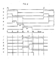
- the suppressing gate circuit 4 provides the amplifier 31 with a suppressing signal "b" during a period corresponding to an echo from a gate signal "a” provided by the transmitting gate circuit 11.
- the signal processing circuit 5 has a short-distance gate 52 and a long-distance gate 51 which, in turn, can receive a gate signal "a" from the transmitting gate circuit 11. Both gates 51 and 52 provide gate signals “c” and “d”, respectively, which rise with gate signal "a” and fall on 5 and 15 cm., respectively, as shown in Fig. 2.
- the gate signals "a”, “b”, “c”, and “d” have respective fixed gate timing periods.
- gate signals "e”. "f”, and “g” rise on 5 cm., 10 cm., and 15 cm., respectively, while falling on detecting ranges designated as “n”, “2n”, and “3n”, respectively (wherein “n” is less than 10 cm.), which are variable according to detecting ranges.
- the gate signal "e” is suppressed by suppress signal "b” so that wave forming circuit 33 does not receive any pulse signals and output Q of flip-flop circuit 57 stays low.
- the second reflective signal returns at the point of 14 cm., designated as "i” in Fig. 2, whereby gate signal “f” is high so that flip-flop circuit 56 is set to make its output Q high, designated as "j” in Fig. 2.
- the AND gate 60 provides an output "k” at the distance of 15 cm., wherein gate signal “g” becomes high. The output "k” remains high up to the point of 24 cm., wherein gate signal "g” goes down.
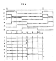
- the output "k” remains high up to 30 cm., wherein gate signal “g” goes down.
- the second reflective signal “i” comes in at the point of 28 cm., wherein flip-flop circuit 58 is set to provide a signal "l".
- the signal "l” is inputted into flip-flop circuit 59 through the OR gate 61, in order to produce a detecting signal "o".
- presetting of gate timings using preset circuit 6 is performed so that gate signals "e", "f", and “g" have opening periods of 5 to 20 cm., 10 to 20 cm., and 15 to 30 cm., respectively.
Landscapes
- Physics & Mathematics (AREA)
- Engineering & Computer Science (AREA)
- Radar, Positioning & Navigation (AREA)
- Remote Sensing (AREA)
- Acoustics & Sound (AREA)
- Computer Networks & Wireless Communication (AREA)
- General Physics & Mathematics (AREA)
- Measurement Of Velocity Or Position Using Acoustic Or Ultrasonic Waves (AREA)
Applications Claiming Priority (2)
| Application Number | Priority Date | Filing Date | Title |
|---|---|---|---|
| JP207455/86 | 1986-09-02 | ||
| JP61207455A JPH06100651B2 (ja) | 1986-09-02 | 1986-09-02 | 超音波スイツチ |
Publications (2)
| Publication Number | Publication Date |
|---|---|
| EP0258874A2 true EP0258874A2 (fr) | 1988-03-09 |
| EP0258874A3 EP0258874A3 (fr) | 1989-01-18 |
Family
ID=16540053
Family Applications (1)
| Application Number | Title | Priority Date | Filing Date |
|---|---|---|---|
| EP87112745A Withdrawn EP0258874A3 (fr) | 1986-09-02 | 1987-09-01 | Commutateur de détection d'un objet |
Country Status (3)
| Country | Link |
|---|---|
| US (1) | US5008862A (fr) |
| EP (1) | EP0258874A3 (fr) |
| JP (1) | JPH06100651B2 (fr) |
Families Citing this family (5)
| Publication number | Priority date | Publication date | Assignee | Title |
|---|---|---|---|---|
| US5177711A (en) * | 1986-09-02 | 1993-01-05 | Omron Tateisi Electronics | Object detecting switch device |
| US5373482A (en) * | 1990-02-26 | 1994-12-13 | Trend Tec Inc. | Distance measuring system arranged to limit false indications of distance measurements |
| US5459698A (en) * | 1993-03-08 | 1995-10-17 | The Rexroth Corporation | Noninvasive ultrasonic proximity detector for a fluid actuated cylinder |
| JP2002090452A (ja) * | 2000-09-14 | 2002-03-27 | Nippon Ceramic Co Ltd | 超音波距離計 |
| JP5807197B2 (ja) * | 2011-04-13 | 2015-11-10 | パナソニックIpマネジメント株式会社 | 物体検知装置 |
Citations (6)
| Publication number | Priority date | Publication date | Assignee | Title |
|---|---|---|---|---|
| US2629867A (en) * | 1943-04-17 | 1953-02-24 | Allen H Schooley | Range aperturing device |
| US3412390A (en) * | 1965-10-14 | 1968-11-19 | Westinghouse Electric Corp | Echo ranging system for monitoring plurality of detection zones to determine presence of absence of objects |
| US3680039A (en) * | 1970-10-08 | 1972-07-25 | Thomas K Tsao | Apparatus for detecting movable objects |
| US3760343A (en) * | 1969-10-20 | 1973-09-18 | Gen Signal Corp | Apparatus for controlling sonic energy distribution |
| US3781772A (en) * | 1972-02-25 | 1973-12-25 | Matsushita Electric Works Ltd | Ultrasonic detection apparatus |
| EP0156636A2 (fr) * | 1984-03-22 | 1985-10-02 | Salubre Investments Limited | Traitement de signaux écho |
Family Cites Families (8)
| Publication number | Priority date | Publication date | Assignee | Title |
|---|---|---|---|---|
| US4332016A (en) * | 1979-01-26 | 1982-05-25 | A/S Tomra Systems | Method, apparatus and transducer for measurement of dimensions |
| US4326273A (en) * | 1980-07-23 | 1982-04-20 | Hurst Performance, Inc. | Ultrasonic ranging device |
| US4489319A (en) * | 1981-03-06 | 1984-12-18 | Raytheon Company | Detector with variance sensitivity |
| DE3207950A1 (de) * | 1982-03-05 | 1983-09-15 | Bosch Gmbh Robert | Abstandsmessvorrichtung |
| JPS5937459A (ja) * | 1982-08-27 | 1984-02-29 | Automob Antipollut & Saf Res Center | 超音波による物体検出装置 |
| US4679175A (en) * | 1984-12-13 | 1987-07-07 | Honeywell Inc. | Ultrasonic distance sensor with dual burst noise rejection |
| US4717916A (en) * | 1986-05-16 | 1988-01-05 | Holodyne Ltd., 1986 | High resolution imaging doppler interferometer |
| US4785429A (en) * | 1987-03-04 | 1988-11-15 | Folwell Dale E | Range control system |
-
1986
- 1986-09-02 JP JP61207455A patent/JPH06100651B2/ja not_active Expired - Lifetime
-
1987
- 1987-09-01 EP EP87112745A patent/EP0258874A3/fr not_active Withdrawn
-
1990
- 1990-01-18 US US07/465,603 patent/US5008862A/en not_active Expired - Fee Related
Patent Citations (6)
| Publication number | Priority date | Publication date | Assignee | Title |
|---|---|---|---|---|
| US2629867A (en) * | 1943-04-17 | 1953-02-24 | Allen H Schooley | Range aperturing device |
| US3412390A (en) * | 1965-10-14 | 1968-11-19 | Westinghouse Electric Corp | Echo ranging system for monitoring plurality of detection zones to determine presence of absence of objects |
| US3760343A (en) * | 1969-10-20 | 1973-09-18 | Gen Signal Corp | Apparatus for controlling sonic energy distribution |
| US3680039A (en) * | 1970-10-08 | 1972-07-25 | Thomas K Tsao | Apparatus for detecting movable objects |
| US3781772A (en) * | 1972-02-25 | 1973-12-25 | Matsushita Electric Works Ltd | Ultrasonic detection apparatus |
| EP0156636A2 (fr) * | 1984-03-22 | 1985-10-02 | Salubre Investments Limited | Traitement de signaux écho |
Also Published As
| Publication number | Publication date |
|---|---|
| JPH06100651B2 (ja) | 1994-12-12 |
| JPS6361976A (ja) | 1988-03-18 |
| US5008862A (en) | 1991-04-16 |
| EP0258874A3 (fr) | 1989-01-18 |
Similar Documents
| Publication | Publication Date | Title |
|---|---|---|
| US4382291A (en) | Surveillance system in which a reflected signal pattern is compared to a reference pattern | |
| DE3176130D1 (en) | Circuit for determining and displaying when the distance between a vehicle and an obstacle falls below predetermined minimum values | |
| US4482889A (en) | Device for detecting failure of ultrasonic apparatus | |
| WO2000005597A3 (fr) | Systemes a echo d'impulsion a faible distance de precision dotes de detecteurs d'impulsions automatiques | |
| US4622553A (en) | Radar detector | |
| US4914951A (en) | Apparatus for remote distance measurement | |
| US5177711A (en) | Object detecting switch device | |
| US5008862A (en) | Object detecting switch device | |
| JPH02223884A (ja) | 移動物体検知装置 | |
| US4467362A (en) | Apparatus and method for transmitting ultrasonic wave | |
| JP2828678B2 (ja) | 超音波検知器 | |
| US4214314A (en) | Precision transponder and method of communicating therewith | |
| JPS61172085A (ja) | 測距型物体検知装置 | |
| JP2904391B2 (ja) | 超音波センサ | |
| JP3066545B2 (ja) | 侵入物体検知機能を有した超音波センサ | |
| JPH037827Y2 (fr) | ||
| JP2801997B2 (ja) | 潮流測定方法 | |
| JPH03180794A (ja) | 超音波距離測定方法及び装置 | |
| JPS63128278A (ja) | 超音波等を用いた検知装置 | |
| JPS6147387B2 (fr) | ||
| KR860000456B1 (ko) | 거리 측정 장치 | |
| JPS6343718B2 (fr) | ||
| JPH0334710Y2 (fr) | ||
| JPH0483192A (ja) | 超音波センサ | |
| JPH04242189A (ja) | 超音波検知器 |
Legal Events
| Date | Code | Title | Description |
|---|---|---|---|
| PUAI | Public reference made under article 153(3) epc to a published international application that has entered the european phase |
Free format text: ORIGINAL CODE: 0009012 |
|
| 17P | Request for examination filed |
Effective date: 19870901 |
|
| AK | Designated contracting states |
Kind code of ref document: A2 Designated state(s): AT BE CH DE ES FR GB GR IT LI LU NL SE |
|
| PUAL | Search report despatched |
Free format text: ORIGINAL CODE: 0009013 |
|
| AK | Designated contracting states |
Kind code of ref document: A3 Designated state(s): AT BE CH DE ES FR GB GR IT LI LU NL SE |
|
| 17Q | First examination report despatched |
Effective date: 19901129 |
|
| STAA | Information on the status of an ep patent application or granted ep patent |
Free format text: STATUS: THE APPLICATION HAS BEEN WITHDRAWN |
|
| 18W | Application withdrawn |
Withdrawal date: 19910405 |
|
| R18W | Application withdrawn (corrected) |
Effective date: 19910405 |
|
| RIN1 | Information on inventor provided before grant (corrected) |
Inventor name: SHIMAMOTO, HIROSHIOMRON TATEISI ELECTRONICS CO. Inventor name: YAMAGUCHI, YUKIOOMRON TATEISI ELECTRONICS CO. Inventor name: SUZAKI, HIDEYUKIOMRON TATEISI ELECTRONICS CO. Inventor name: KAWANO, ATUSI OMRON TATEISI ELECTRONICS CO. |