EP0254038B1 - Sicherheitseinrichtung für ein Türsystem - Google Patents
Sicherheitseinrichtung für ein Türsystem Download PDFInfo
- Publication number
- EP0254038B1 EP0254038B1 EP87108821A EP87108821A EP0254038B1 EP 0254038 B1 EP0254038 B1 EP 0254038B1 EP 87108821 A EP87108821 A EP 87108821A EP 87108821 A EP87108821 A EP 87108821A EP 0254038 B1 EP0254038 B1 EP 0254038B1
- Authority
- EP
- European Patent Office
- Prior art keywords
- closing
- door
- force
- servomotor
- control motor
- Prior art date
- Legal status (The legal status is an assumption and is not a legal conclusion. Google has not performed a legal analysis and makes no representation as to the accuracy of the status listed.)
- Expired - Lifetime
Links
- 238000000034 method Methods 0.000 claims abstract description 13
- 230000008569 process Effects 0.000 claims abstract description 13
- 230000033001 locomotion Effects 0.000 claims description 3
- 230000000694 effects Effects 0.000 claims description 2
- 230000003213 activating effect Effects 0.000 claims 1
- 238000006243 chemical reaction Methods 0.000 abstract description 5
- 230000004044 response Effects 0.000 abstract description 3
- 238000013022 venting Methods 0.000 description 3
- 208000027418 Wounds and injury Diseases 0.000 description 2
- 230000006835 compression Effects 0.000 description 2
- 238000007906 compression Methods 0.000 description 2
- 230000006378 damage Effects 0.000 description 2
- 208000014674 injury Diseases 0.000 description 2
- 230000009467 reduction Effects 0.000 description 2
- 230000008901 benefit Effects 0.000 description 1
- 238000010276 construction Methods 0.000 description 1
- 230000008878 coupling Effects 0.000 description 1
- 238000010168 coupling process Methods 0.000 description 1
- 238000005859 coupling reaction Methods 0.000 description 1
- 230000001419 dependent effect Effects 0.000 description 1
- 230000036316 preload Effects 0.000 description 1
- 230000002035 prolonged effect Effects 0.000 description 1
- 230000001105 regulatory effect Effects 0.000 description 1
- 230000033764 rhythmic process Effects 0.000 description 1
Images
Classifications
-
- E—FIXED CONSTRUCTIONS
- E05—LOCKS; KEYS; WINDOW OR DOOR FITTINGS; SAFES
- E05F—DEVICES FOR MOVING WINGS INTO OPEN OR CLOSED POSITION; CHECKS FOR WINGS; WING FITTINGS NOT OTHERWISE PROVIDED FOR, CONCERNED WITH THE FUNCTIONING OF THE WING
- E05F15/00—Power-operated mechanisms for wings
- E05F15/40—Safety devices, e.g. detection of obstructions or end positions
- E05F15/41—Detection by monitoring transmitted force or torque; Safety couplings with activation dependent upon torque or force, e.g. slip couplings
-
- E—FIXED CONSTRUCTIONS
- E05—LOCKS; KEYS; WINDOW OR DOOR FITTINGS; SAFES
- E05F—DEVICES FOR MOVING WINGS INTO OPEN OR CLOSED POSITION; CHECKS FOR WINGS; WING FITTINGS NOT OTHERWISE PROVIDED FOR, CONCERNED WITH THE FUNCTIONING OF THE WING
- E05F15/00—Power-operated mechanisms for wings
- E05F15/40—Safety devices, e.g. detection of obstructions or end positions
-
- E—FIXED CONSTRUCTIONS
- E05—LOCKS; KEYS; WINDOW OR DOOR FITTINGS; SAFES
- E05F—DEVICES FOR MOVING WINGS INTO OPEN OR CLOSED POSITION; CHECKS FOR WINGS; WING FITTINGS NOT OTHERWISE PROVIDED FOR, CONCERNED WITH THE FUNCTIONING OF THE WING
- E05F15/00—Power-operated mechanisms for wings
- E05F15/50—Power-operated mechanisms for wings using fluid-pressure actuators
- E05F15/56—Power-operated mechanisms for wings using fluid-pressure actuators for horizontally-sliding wings
- E05F15/565—Power-operated mechanisms for wings using fluid-pressure actuators for horizontally-sliding wings for railway-cars
-
- E—FIXED CONSTRUCTIONS
- E05—LOCKS; KEYS; WINDOW OR DOOR FITTINGS; SAFES
- E05Y—INDEXING SCHEME ASSOCIATED WITH SUBCLASSES E05D AND E05F, RELATING TO CONSTRUCTION ELEMENTS, ELECTRIC CONTROL, POWER SUPPLY, POWER SIGNAL OR TRANSMISSION, USER INTERFACES, MOUNTING OR COUPLING, DETAILS, ACCESSORIES, AUXILIARY OPERATIONS NOT OTHERWISE PROVIDED FOR, APPLICATION THEREOF
- E05Y2400/00—Electronic control; Electrical power; Power supply; Power or signal transmission; User interfaces
- E05Y2400/10—Electronic control
- E05Y2400/30—Electronic control of motors
- E05Y2400/31—Force or torque control
-
- E—FIXED CONSTRUCTIONS
- E05—LOCKS; KEYS; WINDOW OR DOOR FITTINGS; SAFES
- E05Y—INDEXING SCHEME ASSOCIATED WITH SUBCLASSES E05D AND E05F, RELATING TO CONSTRUCTION ELEMENTS, ELECTRIC CONTROL, POWER SUPPLY, POWER SIGNAL OR TRANSMISSION, USER INTERFACES, MOUNTING OR COUPLING, DETAILS, ACCESSORIES, AUXILIARY OPERATIONS NOT OTHERWISE PROVIDED FOR, APPLICATION THEREOF
- E05Y2400/00—Electronic control; Electrical power; Power supply; Power or signal transmission; User interfaces
- E05Y2400/10—Electronic control
- E05Y2400/52—Safety arrangements associated with the wing motor
- E05Y2400/53—Wing impact prevention or reduction
- E05Y2400/54—Obstruction or resistance detection
- E05Y2400/55—Obstruction or resistance detection by using load sensors
- E05Y2400/552—Switches
-
- E—FIXED CONSTRUCTIONS
- E05—LOCKS; KEYS; WINDOW OR DOOR FITTINGS; SAFES
- E05Y—INDEXING SCHEME ASSOCIATED WITH SUBCLASSES E05D AND E05F, RELATING TO CONSTRUCTION ELEMENTS, ELECTRIC CONTROL, POWER SUPPLY, POWER SIGNAL OR TRANSMISSION, USER INTERFACES, MOUNTING OR COUPLING, DETAILS, ACCESSORIES, AUXILIARY OPERATIONS NOT OTHERWISE PROVIDED FOR, APPLICATION THEREOF
- E05Y2800/00—Details, accessories and auxiliary operations not otherwise provided for
- E05Y2800/40—Physical or chemical protection
-
- E—FIXED CONSTRUCTIONS
- E05—LOCKS; KEYS; WINDOW OR DOOR FITTINGS; SAFES
- E05Y—INDEXING SCHEME ASSOCIATED WITH SUBCLASSES E05D AND E05F, RELATING TO CONSTRUCTION ELEMENTS, ELECTRIC CONTROL, POWER SUPPLY, POWER SIGNAL OR TRANSMISSION, USER INTERFACES, MOUNTING OR COUPLING, DETAILS, ACCESSORIES, AUXILIARY OPERATIONS NOT OTHERWISE PROVIDED FOR, APPLICATION THEREOF
- E05Y2900/00—Application of doors, windows, wings or fittings thereof
- E05Y2900/50—Application of doors, windows, wings or fittings thereof for vehicles
- E05Y2900/53—Type of wing
- E05Y2900/531—Doors
Definitions
- the invention relates to a security device for a door system according to the preamble of patent claim 1.
- Door systems of this type and in particular automatic sliding or pivoting sliding doors of rail vehicles, buses, etc., in which a pneumatic, long-stroke, piston-cylinder unit, which is usually directly connected to the door leaf, is used for reasons of a sufficiently high closing speed with a relatively high working pressure and develop correspondingly strong closing forces in the order of 1000 N when the door hits an obstacle.
- the door controls of such door systems are therefore equipped with a reversing device including a closing force sensor which absorbs the driving force of the servomotor or a contact or pressure bar which extends over the closing edge of the door leaf, which responds when there is a greater clamping force effect and then an electrical, reversing the pneumatic drive Trigger the opening signal.
- a closing force sensor which absorbs the driving force of the servomotor or a contact or pressure bar which extends over the closing edge of the door leaf, which responds when there is a greater clamping force effect and then an electrical, reversing the pneumatic drive Trigger the opening signal.
- the safety valve is activated when the closing force sensor responds switched over to this directly coupled two-position touch valve and a pneumatic timer controlled by it for a predetermined period of time from the rest position releasing the pressure supply line to a venting position connecting the closing pressure side of the servomotor with a low-pressure accumulator, and thereby the driving force of the servomotor when it strikes Obstacle reduced.
- Such a clamping force limitation with a time delay requires its own, pressure-controlled, low-pressure accumulator and an energy and construction-intensive control of the safety valve. Due to the relatively sluggish control behavior, there are also strong deviations of the effective drive or clamping force of the servomotor from the predetermined response value of the closing force sensor and, in the event of a prolonged impediment to the closing movement, a pulsating increase in the clamping force.
- the object of the invention is to provide a safety device for a door system of the type mentioned, which works independently of a reversing device and is designed so that the closing force of the servomotor quickly, regardless of the state of motion of the door in a simple, reliable manner while maintaining a high closing speed and is adjusted to a permissible maximum value with great accuracy.
- the safety device according to the invention which is assigned to the servomotor in the manner of an internal one Closing force control circuit works, even with a high working pressure in the supply line, as is required for a large amount of compressed air to the closing pressure side and a correspondingly high closing speed of the servomotor, ensures that the closing force of the servomotor during the entire closing process to a maximum value that can be set on the sensor is adjusted, regardless of whether a reversing device is now available and responds to an obstacle or not.
- the closing force limitation according to the invention for which only a few, simple and reliable components are required, is extremely insusceptible to faults and works without external energy and with high accuracy and response speed, because the control valve is actuated directly in dependence on the driving force of the servomotor and in its central position, So if the closing force is at the set maximum value, the pressure supply line is initially shut off and in the venting position, i.e.
- the safety device not only minimizes the risk of injury, but in the event of a pinch, even weaker people can free themselves by pushing on the door leaf without great effort, namely by a counterforce that is also limited to the permitted maximum value opposite to the closing direction.
- the maximum clamping force value was in a practical application of the invention in the order of 100 N.
- the closing force sensor is designed as a simple spring element which absorbs the reaction force of the servomotor which acts on the support on the door frame side and is of the same size in the opposite direction to the closing force, which has the advantage that the safety device does not require any parts moving with the door leaf will.
- the rocker characterized in claim 4 is expediently assigned to the servomotor, the control valve and the spring element .
- the stop according to claim 5 ensures that the driving force of the servomotor is only released during the closing process, but not when the door is opened, via the spring element or the closing force sensor.
- the safety device according to the invention is preferably combined with an automatic door system which, as the servomotor, has a pneumatic long-stroke piston-cylinder unit which is effective both in the closing and in the opening direction and whose piston rod directly connected to the door leaf and its cylinder is supported on the door frame side via the closing force sensor or the rocker interacting with the spring element.
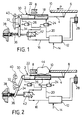
- the automatic door system shown in the figures contains, as the servomotor, a double-acting, pneumatic long-stroke piston-cylinder unit 2, the piston rod 4 of which is connected directly to the sliding door leaf 6, which is actuated by the servomotor 2 in the direction of arrow P on the door jamb or Move door frame 8 and open in the opposite direction.
- the closing edge 10 of the door leaf 6 can be designed as a contact or pressure bar of a reversing device which is of no interest here and therefore not described further.
- the control of the servomotor 2 is carried out by a door control 12, which is connected to a compressed air line 14 from z. B. 5 bar connected and connected via a closing air supply line 16 to the piston rod-side closing pressure chamber 18 and via an air supply line 20 to the cylinder chamber 22 pressurized when the door leaf 6 is opened.
- a door control 12 which is connected to a compressed air line 14 from z. B. 5 bar connected and connected via a closing air supply line 16 to the piston rod-side closing pressure chamber 18 and via an air supply line 20 to the cylinder chamber 22 pressurized when the door leaf 6 is opened.
- changeover valves 24 and 26 respectively, which vent the assigned cylinder chamber 18 or 22 to the outside as soon as this and the assigned supply line have reached the depressurized state, the free connection of the cylinder chamber 18 and 22 block outwards, however, as soon as the supply line 16 or 20 is pressurized and as long as the cylinder chamber 18 or 22 is under pressure.
- the changeover valves 24, 26 prevent a counterpressure from building up in the other cylinder chamber 22 or 18 when the assigned cylinder chamber 18 or 22 is pressurized.
- the changeover valves 24, 26 remain in the position shown during the entire closing process, that is to say also when the safety device described below responds, because the safety device causes the pressure in the closing pressure chamber 18 to be reduced, but this is not completely depressurized.
- a pneumatic door lock 28 is also assigned to the door control 12.
- the door system shown is of conventional construction and functionality.
- the servomotor 2 is one Associated with safety device, by means of which the closing air supply and removal to and from the closing pressure chamber 18 is regulated during the entire closing process in accordance with the effective driving force of the servomotor 2.
- the cylinder 30 of the servomotor 2 is not firmly supported on the door frame 8, but is articulated on a rocker 34 which can be pivoted about a fixed pivot point 32 and which is supported at its free end on a spring member in the form of a compression spring 36, the pretensioning of which - approximately adjustable with the aid of the adjusting screw 38 shown in the figures.
- the door closing force or the reaction force of the servomotor 2, which is of the same magnitude and opposite, is therefore passed from the cylinder 30 via the rocker 34 and the spring member 36 into the door frame 8, while the reaction force of the cylinder 30 when the cylinder chamber 22 is pressurized, i.e. when the door is opened, via a the rocker 34 associated stop 40 is set down.
- the rocker 34 and the spring member 36 by means of which the servomotor 2 is elastically supported in the longitudinal direction on the door frame 8, thus form a closing force sensor which absorbs the driving force of the servomotor during the closing process and which actuates a control valve 42 arranged in the course of the closing air supply line 16.
- the control valve 42 is held in its rest position (FIG. 1) by the rocker 34, in which it clears the supply line 16 to the closing pressure side 18 of the servomotor 2 switches through.
- the closing force sensor responds, ie the rocker 34 is pivoted by the reaction force of the servomotor 2 against the spring force of the compression spring 36, and the control valve 42 is switched over. It first reaches an intermediate position, in which it shuts off the closing pressure side 18 of the servomotor 2 from the closing air supply line 16, and then into the venting position shown in FIG.
- the safety device described also allows the jammed obstacle, and in particular a passenger, to be released without great effort by pushing on the door leaf 6 against the closing force of the servomotor 2 when the closing process is interrupted. If a counterforce is exerted on the door leaf 6 against the closing direction, which exceeds the maximum value set on the spring 36, the safety device also responds so that the closing pressure chamber 18 is vented via the control valve 42 in such a way that the door leaf 6 counteracts one essentially constant resistance limited to the set maximum value of the servomotor 2 can be pressed open.
- the maximum door closing force was limited to 100 N.
- the pressure level associated with this closing force limit value in the closing pressure chamber 18 of the servomotor 2 cannot be precisely determined because it is dependent not only on the effective piston pressure area but also on disturbance variables, for example the internal friction of the servomotor 2.
Landscapes
- Power-Operated Mechanisms For Wings (AREA)
- Burglar Alarm Systems (AREA)
Description
- Die Erfindung bezieht sich auf eine Sicherheitseinrichtung für ein Türsystem nach dem Oberbegriff des Patentanspruchs 1.
- Türsysteme dieser Art, und insbesondere automatische Schiebeoder Schwenkschiebetüren von Schienenfahrzeugen, Bussen etc., bei denen zum Antrieb des Türflügels zumeist eine direkt mit diesem gekoppelte, pneumatische Langhub-Kolben-Zylindereinheit verwendet wird, arbeiten aus Gründen einer ausreichend hohen Schließgeschwindigkeit mit einem relativ großen Arbeitsdruck und entwickeln beim Auftreffen der Tür auf ein Hindernis entsprechend starke Schließkräfte, die in der Größenordnung von 1000 N liegen. Aus Sicherheitsgründen sind die Türsteuerungen derartiger Türsysteme daher mit einer Reversiereinrichtung einschließlich eines die Antriebskraft des Stellmotors federnd aufnehmenden Schließkraftsensors oder einer sich über die Schließkante des Türflügels erstreckenden Kontakt- bzw. Druckleiste ausgerüstet, welche bei einer stärkeren Klemmkraftwirkung ansprechen und dann ein elektrisches, den Pneumatikantrieb umsteuerndes Öffnungssignal auslösen. Dabei hat es sich jedoch als problematisch erwiesen, daß das Hindernis im Rhythmus des periodisch ablaufenden Schließ- und Öffnungsvorgangs wiederholt starken Kraftstößen ausgesetzt ist, so daß derartige Reversiereinrichtungen nur eine begrenzte Sicherung, vor allem von schwächeren Personen gegen eine Verletzungsgefahr beim Schließen der Tür bieten.
- Bei der aus der EP-A-33 646 bekannten Tür-Sicherheitseinrichtung der eingangs genannten Art, die einen Schließkraftsensor mit einem die türrahmenseitige Abstützung des Stellmotors bewirkenden Federglied und ein im Zuge der Schließdruck-Zufuhrleitung angeordnetes Sicherheitsventil enthält, wird das Sicherheitsventil beim Ansprechen des Schließkraftsensors überein mit diesem unmittelbar gekoppeltes Zweistellungs-Tastventil und ein von diesem gesteuertes, pneumatisches Zeitglied für eine vorgegebene Zeitdauer von der die Druckzufuhrleitung freigebenden Ruheposition in eine die Schließdruckseite des Stellmotors mit einem Nieder-druckspeicher verbindende Entlüftungsposition umgeschaltet und dadurch die Antriebskraft des Stellmotors beim Auftreffen auf ein Hindernis reduziert. Eine derartige Schließkraftbegrenzung mit Zeitverzögerung erfordert einen eigenen, druckgeregelten Niederdruckspeicher und eine energie- und bauaufwendige Ansteuerung des Sicherheitsventils. Aufgrund des relativ trägen Regelverhaltens kommt es ferner zu starken Abweichungen der effektiven Antriebs- bzw. Klemmkraft des Stellmotors vom vorgegebenen Ansprechwert des Schließkraftsensors und bei einer länger anhaltenden Behinderung der Schließbewegung zu einer pulsierenden Klemmkrafterhöhung. Aufgabe der Erfindung ist es, eine Sicherheitseinrichtung für ein Türsystem der eingangs genannten Art zu schaffen, die unabhängig von einer Reversiereinrichtung arbeitet und so ausgebildet ist, daß die Schließkraft des Stellmotors unabhängig vom Bewegungszustand der Tür in einfacher, zuverlässiger Weise unter Beibehalt einer hohen Schließgeschwindigkeit rasch und mit großer Genauigkeit auf einen zulässigen Höchstwert einreguliert wird.
- Diese Aufgabe wird erfindungsgemäß durch die im Patentanspruch 1 gekennzeichnete Sicherheitseinrichtung gelöst.
- Durch die erfindungsgemäße Sicherheitseinrichtung, die nach Art eines internen, dem Stellmotor zugeordneten Schließkraft-Regelkreises arbeitet, wird selbst bei einem hohen Arbeitsdruck in der Zufuhrleitung, wie er für eine große Druckluftzuflußmenge zur Schließdruckseite und eine dementsprechend hohe Schließgeschwindigkeit des Stellmotors erforderlich ist, gewährleistet, daß die Schließkraft des Stellmotors während des gesamten Schließvorgangs auf einen am Sensor einstellbaren Höchstwert einreguliert wird, und zwar gleichgültig, ob eine Reversiereinrichtung nun vorhanden ist und beim Auftreffen auf ein Hindernis anspricht oder nicht. Die Schließkraftbegrenzung nach der Erfindung, für die nur wenige, einfache und zuverlässige Bauelemente benötigt werden, ist äußerst störunanfällig und arbeitet ohne Fremdenergie und mit hoher Genauigkeit und Ansprechgeschwindigkeit, weil das Steuerventil unmittelbar in Abhängigkeit von der Antriebskraft des Stellmotors betätigt wird und in seiner Mittelstellung, also wenn die Schließkraft auf dem eingestellten Höchstwert liegt, die Druckzufuhrleitung zunächst absperrt und in der Entlüftungsposition, also bei Überschreiten des vorgegebenen Schließkraftwertes, bei weiterhin gesperrter Zufuhrleitung die Schließdruckseite des Stellmotors mit hoher Geschwindigkeit, aber nur soweit entlüftet, bis infolge der daraus resultierenden Druckverringerung die Antriebskraft des Stellmotors wieder auf den vorgegebnen Höchstwert absinkt, woraufhin das Ventil erneut in die Zwischenposition und nach Fortfall des Hindernisses in die Ruhestellung zurückschaltet und der Schließvorgang sofort mit unverändert hoher Schließgeschwindigkeit beendet wird. Durch die erfindungsgemäße Sicherheitseinrichtung wird nicht nur das Verletzungsrisiko minimiert, sondern im Falle eines Einklemmens können sich auch schwächere Personen durch Aufdrücken des Türflügels ohne große Kraftanstrengung, nämlich durch eine ebenfalls auf den zugelassenen Höchstwert begrenzte Gegenkraft entgegengesetzt zur Schließrichtung, selbst befreien. Der Schließkraft-Höchstwert lag in einem praktischen Anwendungsfall der Erfindung in der Größenordnung von 100 N.
- In besonders bevorzugter Ausgestaltung der Erfindung ist der Schließkraftsensor gemäß Anspruch 2 als einfaches Federglied ausgebildet, das die an der türrahmenseitigen Abstützung wirkende, der Schließkraft entgegengesetzt gleichgroße Reaktionskraft des Stellmotors aufnimmt, was den Vorteil hat, daß für die Sicherheitseinrichtung keinerlei mit dem Türflügel mitbewegte Teile benötigt werden. Zwar ist es ohne weiteres möglich, den zugelassenen Schließkraft-Höchstwert dadurch zu variieren, daß der das Umschalten des Steuerventils auslösende Federweg des Federgliedes veränderlich eingestellt wird, aus Gründen gleichbleibender Schaltwege empfiehlt es sich jedoch gemäß Anspruch 3, zum Zwecke einer Änderung des SchließkraftHöchstwertes die Federvorspannung des Federgliedes zu verstellen.
- Im Hinblick auf eine einfache mechanische Koppelung zwischen Schließkraftsensor und Steuerventil, durch die zugleich eine begrenzt bewegliche Führung des Stellmotors an seiner türrahemenseitigen, aufgrund des Federgliedes elastischen Abstützung erreicht wird, ist zweckmäßigerweise dem Stellmotor, dem Steuerventil und dem Federglied die im Anspruch 4 gekennzeichnete Wippe zugeordnet. Durch den Anschlag gemäß Anspruch 5 wird sichergestellt, daß die Antriebskraft des Stellmotors nur beim Schließvorgang, nicht aber auch beim Öffnen der Tür über das Federglied bzw. den Schließkraftsensor abgesetzt wird.
- Vorzugsweise wird die Sicherheitseinrichtung nach der Erfindung gemäß Anspruch 6 mit einem automatischen Türsystem kombiniert, das als Stellmotor eine pneumatische, sowohl in Schließ- als auch in Öffnungsrichtung wirksame Langhub-Kolben-Zylindereinheit besitzt, deren Kolbenstange unmittelbar an den Türflügel angeschlossen und deren Zylinder türrahmenseitig über den Schließkraftsensor bzw. die mit dem Federglied zusammenwirkende Wippe abgestützt ist.
- Die Erfindung wird nunmehr anhand eines Ausführungsbeispieles in Verbindung mit den Zeichnungen näher erläutert. Es zeigen in schematischer Darstellung:
- Fig. 1
- die Sicherheitseinrichtung im Ruhezustand mit zugeordnetem Türsystem während des Schließvorgangs,
- Fig. 2
- eine der Fig. 1 entsprechende Darstellung, jedoch mit zum Zwecke der Schließkraftbegrenzung aktivierter Sicherheitseinrichtung nach Auftreffen des Türflügels auf ein Hindernis.
- Das in den Fig. gezeigte, automatische Türsystem enthält als Stellmotor eine doppelt wirkende, pneumatische Langhub-Kolben-Zylindereinheit 2, deren Kolbenstange 4 unmittelbar an den Schiebetürflügel 6 angeschlossen ist, welcher durch den Stellmotor 2 beim Schließvorgang in Pfeilrichtung P auf den Türpfosten bzw. Türrahmen 8 verfahren und in entgegengesetzter Richtung geöffnet wird. Die Schließkante 10 des Türflügels 6 kann als Kontakt- oder Druckleiste einer hier nicht näher interessierenden und daher auch nicht weiter beschriebenen Reversiereinrichtung ausgebildet sein.
- Die Steuerung des Stellmotors 2 erfolgt durch eine Türsteuerung 12, die an eine Druckluftleitung 14 von z. B. 5 bar angeschlossen und über eine Schließluf-Zufuhrleitung 16 mit der kolbenstangenseitigen Schließdruckkammer 18 sowie über eine Luftzufuhrleitung 20 mit der beim Öffnen des Türflügels 6 druckbeaufschlagten Zylinderkammer 22 verbunden ist. Im Zuge der Zufuhrleitungen 16 und 20 befinden sich jeweils selbsttätig arbeitende Umschaltventile 24 bzw. 26, die die zugeordnete Zylinderkammer 18 bzw. 22 nach außen entlüften, sobald diese und die zugeordnete Zufuhrleitung in den drucklosen Zustand gelangt sind, die freie Verbindung der Zylinderkammer 18 bzw. 22 nach außen jedoch sperren, sobald die Zufuhrleitung 16 bzw. 20 druckbeaufschlagt wird und solange die Zylinderkammer 18 bzw. 22 unter Druck steht. Mit anderen Worten verhindern die Umschaltventile 24, 26, daß sich bei Druckbeaufschlagung der zugeordneten Zylinderkammer 18 bzw. 22 ein Gegendruck in der jeweils anderen Zylinderkammer 22 bzw. 18 aufbauen kann. Die Umschaltventile 24, 26 verbleiben während des gesamten Schließvorganges, also auch beim Ansprechen der weiter unten beschriebenen Sicherheitseinrichtung, in der gezeigten Stellung, weil durch die Sicherheitseinrichtung allenfalls eine Druckabsenkung der Schließdruckkammer 18 bewirkt, diese aber nicht völlig drucklos geschaltet wird. Der Türsteuerung 12 ist ferner eine pneumatische Türverriegelung 28 zugeordnet. Insoweit ist das gezeigte Türsystem von üblicher Bau- und Funktionsweise.
- Um nun die maximal wirksame Türschließkraft auf einen veränderlich einstellbaren Wert zu begrenzen, der zum Zwecke der Sicherung insbesondere von Personen so gering wie unter Beibehalt ausreichend kurzer Schaltzeiten möglich gewählt wird, ist dem Stellmotor 2 eine Sicherheitseinrichtung zugeordnet, durch die die Schließluftzu- und -abfuhr zu und von der Schließdruckkammer 18 während des gesamten Schließvorganges nach Maßgabe der effektiven Antriebskraft des Stellmotors 2 geregelt wird. Zu diesem Zweck ist der Zylinder 30 des Stellmotors 2 am Türrahmen 8 nicht fest abgestützt, sondern gelenkig an einer um einen ortsfesten Drehpunkt 32 schwenkbaren Wippe 34 gelagert, die sich an ihrem freien Ende an einem Federglied in Form einer Druckfeder 36 abstützt, deren Vorspannung - etwa mit Hilfe der in den Fig. gezeigten Stellschraube 38 - veränderlich einstellbar ist.
- Die Türschließkraft bzw. die dieser entgegengesetzt gleichgroße Reaktionskraft des Stellmotors 2 wird daher vom Zylinder 30 über die Wippe 34 und das Federglied 36 in den Türrahmen8 geleitet, während die Reaktionskraft des Zylinders 30 bei Druckbeaufschlagung der Zylinderkammer 22, also beim Öffnen der Türe, über einen der Wippe 34 zugeordneten Anschlag 40 abgesetzt wird.
- Die Wippe 34 und das Federglied 36, durch die der Stellmotor 2 in Längsrichtung elastisch am Türrahmen 8 abgestützt wird, bilden somit einen die Antriebskraft des Stellmotors beim Schließvorgang aufnehmenden Schließkraftsensor, der ein im Zuge der Schließluft-Zufuhrleitung 16 angeordnetes Steuerventil 42 betätigt. Solange die effektive Antriebskraft des Stellmotors 2 unterhalb des durch die Vorspannung der Feder 36 eingestellten Grenzwertes verbleibt, wird das Steuerventil 42 durch die Wippe 34 in seiner Ruhestellung (Fig. 1) gehalten, in der es die Zufuhrleitung 16 zur Schließdruckseite 18 des Stellmotors 2 frei durchschaltet.
- Sobald der Türflügel 6 beim Schließvorgang jedoch gegen ein Hindernis 44 (Fig. 2) fährt und die Schließkraft des Stellmotors 2 den vorgegebenen Grenzwert erreicht, spricht der Schließkraftsensor an, d. h. die Wippe 34 wird durch die Reaktionskraft des Stellmotors 2 entgegen der Federkraft der Druckfeder 36 verschwenkt, und das Steuerventil 42 wird umgeschaltet. Es gelangt zunächst in eine Zwischenstellung, in der es die Schließdruckseite 18 des Stellmotors 2 von der Schließluft-Zufuhrleitung 16 absperrt, und dann in die in Fig. 2 gezeigte Entlüftungsstellung, in der bei weiterhin gesperrter Zufuhrleitung 16 Druckluft von der Schließdruckseite 18 des Stellmotors 2 ins Freie entweicht, bis durch die daraus resultierende Druckverringerung auf der Schließdruckseite 18 die Antriebskraft des Stellmotors 2 soweit reduziert wird, daß die Wippe 34 und über diese der Zylinder 30 unter der Druckkraft des Federgliedes 36 wieder zurückgestellt und das Steuerventil 42 erneut in die Zwischenstellung und - bei Fortfall des Hindernisses 44 -in die Ruhestellung umgeschaltet wird, woraufhin der Schließvorgang unter der Kontrolle der Türsteuerung 12 automatisch fortgesetzt wird.
- Die beschriebene Sicherheitseinrichtung gestattet es auch, bei einer Unterbrechung des Schließvorganges das eingeklemmte Hindernis, und insbesondere einen Passagier, ohne große Kraftanstrengung durch Aufschieben des Türflügels 6 entgegen der Schließkraft des Stellmotors 2 zu befreien. Wird nämlich auf den Türflügel 6 eine Gegenkraft entgegen der Schließrichtung augeübt, die den an der Feder 36 eingestellten Höchstwert übersteigt, so spricht die Sicherheitseinrichtung gleichfalls an, so daß die Schließdruckkammer 18 über das Steuerventil 42 derart entlüftet wird, daß sich der Türflügel 6 entgegen einer im wesentlichen konstanten und auf den eingestellten Höchstwert begrenzten Widerstandskraft des Stellmotors 2 aufdrücken läßt.
- In einem praktischen Anwendungsfall wurde die maximale Türschließkraft auf 100 N begrenzt. Das diesem Schließkraft-Grenzwert zugeordnete Druckniveau in der Schließdruckkammer 18 des Stellmotors 2 läßt sich nicht genau festlegen, weil es nicht nur von der wirksamen Kolbendruckfläche, sondern auch von Störgrößen, etwa der Innenreibung des Stellmotors 2 abhängig ist.
Claims (6)
- Sicherheitseinrichtung für ein Türsystem, insbesondere für die automatische Schiebetüre eines Schienenfahrzeugs, mit einem druckmittelbetätigten Türflügel-Stellmotor (2) und einer der Schließdruckseite des Stellmotors zugeordneten Türsteuerung (12), die einen die Antriebskraft des Stellmotors federnd aufnehmenden Schließkraftsensor (34,36) und ein sensorgesteuertes, oberhalb eines vorgegebenen Ansprechwertes des Schließkraftsensors die Schließdruckseite des Stellmotors (2) entlüftendes, im Zuge der Schließdruck-Zufuhrleitung des Stellmotors angeordnetes Sicherheitsventil (42) enthält,
dadurch gekennzeichnet, daß
das Sicherheitsventil als stellwegkonform mit dem Schließkraftsensor (34, 36) gekoppeltes Steuerventil (42) mit einer durch den Schließkraftsensor ansteuerbaren, die Druckzufuhrleitung (16) sperrenden Zwischenposition und einer bei weiter gesperrter Zufuhrleitung einen freien Druckmittelabstrom von der StellmotorSchließdruckseite (18) gestattenden Entlüftungsposition ausgebildet ist.
- Sicherheitseinrichtung nach Anspruch 1,
dadurch gekennzeichnet, daß
der Schließkraftsensor (34, 36) ein die türrahmenseitige Abstützung des Stellmotors (2) bewirkendes Federglied (36) enthält. - Sicherheitseinrichtung nach Anspruch 2,
dadurch gekennzeichnet, daß
die das Umschalten des Steuerventils (42) in die Entlüftungsstellung bewirkende Federkraft durch Änderung der Federvorspannung einstellbar ist. - Sicherheitseinrichtung nach Anspruch 2 oder 3,
dadurch gekennzeichnet, daß
der Stellmotor (2) türrahmenseitig an einer um einen ortsfesten Drehpunkt (32) gelagerten, in Richtung der beim Schließvorgang wirkenden Reaktionskraft des Stellmotors (2) entgegen der Kraft des Federgliedes (36) schwenkbaren, das Steuerventil (42) betätigenden Wippe (34) begrenzt beweglich abgestützt ist. - Sicherheitseinrichtung nach Anspruch 4,
gekennzeichnet durch
einen die Schwenkbewegung der Wippe (34) in Richtung der beim Öffnen des Türflügels (6) einwirkenden Reaktionskraft des Stellmotors (2) begrenzenden Anschlag (40). - Sicherheitseinrichtung nach einem der vorhergehenden Ansprüche,
dadurch gekennzeichnet, daß
als Stellmotor (2) eine doppelt wirkende, pneumatische Langhub-Kolben-Zylindereinheit mit einer an den Türflügel (6) angeschlossener Kolbenstange (4) und einem über den Schließkraftsensor (34, 36) türrahmenseitig abgestützten Arbeitszylinder (30) vorgesehen ist.
Priority Applications (1)
| Application Number | Priority Date | Filing Date | Title |
|---|---|---|---|
| AT87108821T ATE61647T1 (de) | 1986-07-23 | 1987-06-19 | Sicherheitseinrichtung fuer ein tuersystem. |
Applications Claiming Priority (2)
| Application Number | Priority Date | Filing Date | Title |
|---|---|---|---|
| DE19863624823 DE3624823A1 (de) | 1986-07-23 | 1986-07-23 | Sicherheitseinrichtung fuer ein tuersystem |
| DE3624823 | 1986-07-23 |
Publications (3)
| Publication Number | Publication Date |
|---|---|
| EP0254038A2 EP0254038A2 (de) | 1988-01-27 |
| EP0254038A3 EP0254038A3 (en) | 1988-06-08 |
| EP0254038B1 true EP0254038B1 (de) | 1991-03-13 |
Family
ID=6305748
Family Applications (1)
| Application Number | Title | Priority Date | Filing Date |
|---|---|---|---|
| EP87108821A Expired - Lifetime EP0254038B1 (de) | 1986-07-23 | 1987-06-19 | Sicherheitseinrichtung für ein Türsystem |
Country Status (4)
| Country | Link |
|---|---|
| US (1) | US4803807A (de) |
| EP (1) | EP0254038B1 (de) |
| AT (1) | ATE61647T1 (de) |
| DE (2) | DE3624823A1 (de) |
Families Citing this family (15)
| Publication number | Priority date | Publication date | Assignee | Title |
|---|---|---|---|---|
| US4981084A (en) * | 1989-04-05 | 1991-01-01 | Morrison-Knudsen Company, Inc. | Transit car door system and operation |
| FR2693535B1 (fr) * | 1992-07-10 | 1994-09-30 | Rockwell Abs France | Dispositif de sécurité pour lève-vitre électriques de véhicule à câble. |
| FR2693569B1 (fr) * | 1992-07-10 | 1994-10-07 | Rockwell Abs France | Dispositif de sécurité pour lève-vitre électriques de véhicule du type à câble coulissant le long d'un rail de guidage. |
| US5402075A (en) * | 1992-09-29 | 1995-03-28 | Prospects Corporation | Capacitive moisture sensor |
| US5955854A (en) * | 1992-09-29 | 1999-09-21 | Prospects Corporation | Power driven venting of a vehicle |
| WO1994020890A1 (en) * | 1993-03-12 | 1994-09-15 | Prospects Corporation | Automatic venting system for a vehicle |
| SE516950C2 (sv) * | 1999-05-21 | 2002-03-26 | Scania Cv Ab | Säkerhetsanordning vid fordonsdörrar |
| AT414005B (de) * | 2002-05-22 | 2006-08-15 | Knorr Bremse Gmbh | Türspaltüberwachung |
| WO2012033431A1 (ru) * | 2010-09-10 | 2012-03-15 | Khrustalev Khristofor Borisovich | Автоматическая дверь |
| JP5631180B2 (ja) * | 2010-12-01 | 2014-11-26 | 東日本旅客鉄道株式会社 | 車両用乗降扉の空気式戸閉装置 |
| DE112010006054A5 (de) * | 2010-12-08 | 2013-10-02 | Gebr. Bode Gmbh & Co. Kg | Kraftgesteuerte Drehmomentstütze |
| CN106948699B (zh) * | 2017-05-03 | 2018-06-05 | 北京汽车研究总院有限公司 | 一种汽车尾门自动开关装置和汽车 |
| DE102018110608B4 (de) * | 2018-05-03 | 2025-07-03 | Kiekert Aktiengesellschaft | Kraftfahrzeug-Antriebsanordnung |
| JP7808442B2 (ja) * | 2021-08-10 | 2026-01-29 | ナブテスコ株式会社 | 空気式ドア装置 |
| US12338903B2 (en) | 2022-07-26 | 2025-06-24 | Lg Energy Solution, Ltd. | Elevatable chamber and method of operating the same |
Family Cites Families (8)
| Publication number | Priority date | Publication date | Assignee | Title |
|---|---|---|---|---|
| DE955292C (de) * | 1953-07-26 | 1957-01-03 | Friedrich Wilhelm Kiekert | Sicherheitseinrichtung fuer Tueren, insbesondere Fahrzeugtueren, die durch einen Kraftantrieb geschlossen werden |
| DE1584037B1 (de) * | 1963-10-25 | 1969-10-23 | Haegglund & Soener Ab | Sicherheitsschalteinrichtung fuer hydraulisch betaetigte Kolben-Zylinder-Antriebe von Tueren,Luken od.dgl. |
| FR1412098A (fr) * | 1964-10-17 | 1965-09-24 | Haegglund & Soener Ab | Dispositif d'asservissement de sécurité de la fermeture à commande hydraulique de portes, trappes ou analogues |
| GB1170451A (en) * | 1966-01-12 | 1969-11-12 | Harefield Rubber Company Ltd | Improvements in or relating to Drive Mechanism |
| US4476678A (en) * | 1980-01-31 | 1984-10-16 | Plc Peters Limited | Control mechanism for pneumatic apparatus |
| DE3213491C1 (de) * | 1982-04-10 | 1983-07-21 | Adam Opel AG, 6090 Rüsselsheim | Sicherheitseinrichtung an beweglichen Schliessteilen,insbesondere an Schutzklappen von Bearbeitungsmaschinen |
| HU191517B (en) * | 1983-04-11 | 1987-03-30 | Finoszerelvenygyar | Device for automatic back opening first the doors or sliding doors of passenger vehicles operated by rotary column |
| DE3439613A1 (de) * | 1984-10-30 | 1986-05-07 | Daimler-Benz Ag, 7000 Stuttgart | Pneumatische tuerbetaetigungsanlage fuer fahrzeuge |
-
1986
- 1986-07-23 DE DE19863624823 patent/DE3624823A1/de active Granted
-
1987
- 1987-06-19 DE DE8787108821T patent/DE3768573D1/de not_active Expired - Lifetime
- 1987-06-19 EP EP87108821A patent/EP0254038B1/de not_active Expired - Lifetime
- 1987-06-19 AT AT87108821T patent/ATE61647T1/de not_active IP Right Cessation
- 1987-07-10 US US07/072,020 patent/US4803807A/en not_active Expired - Fee Related
Also Published As
| Publication number | Publication date |
|---|---|
| DE3624823A1 (de) | 1988-02-04 |
| EP0254038A2 (de) | 1988-01-27 |
| US4803807A (en) | 1989-02-14 |
| EP0254038A3 (en) | 1988-06-08 |
| DE3768573D1 (de) | 1991-04-18 |
| ATE61647T1 (de) | 1991-03-15 |
| DE3624823C2 (de) | 1991-06-27 |
Similar Documents
| Publication | Publication Date | Title |
|---|---|---|
| EP0254038B1 (de) | Sicherheitseinrichtung für ein Türsystem | |
| EP0086267B1 (de) | Elektropneumatische Türsteuerung | |
| EP2138442A1 (de) | Aufzugtürsystem mit Kabinentürverriegelung | |
| EP1154112A2 (de) | Betätigungsanordnung zum Öffnen und Schliessen von schwenkbaren Fahrzeugflügeln | |
| EP3027828B1 (de) | Kraftfahrzeugtür | |
| EP3032017B1 (de) | Vorrichtung zur beeinflussung der öffnungs- und/oder schliessbewegung eines tür- oder fensterflügels | |
| DE3502752C2 (de) | ||
| EP0959217A2 (de) | Anordnung zur hydraulischen Betätigung eines Heckdeckels | |
| DE3441005A1 (de) | Pneumatischer arbeitszylinder mit pneumatischer endlagendaempfung | |
| DE3130699C2 (de) | Omnibus mit einer kraftbetätigten Tür | |
| DE102018210277B4 (de) | Ventil | |
| DE3234615A1 (de) | Tuerbetaetigungsvorrichtung | |
| DE3105867C2 (de) | Schaltungsanordnung für druckmittelbetätigte, insbesondere pneumatisch betätigte, Türen in Fahrzeugen, wie Omnibussen, Straßenbahnen o.dgl. | |
| DE3340319A1 (de) | Halteeinrichtung fuer ein schiffshebewerk | |
| DE2050761A1 (de) | Vorrichtung zur Bewegungssteuerung mittels eines hydraulischen Druckzylin ders | |
| DE2914933C2 (de) | Druckmittelbetriebene Fernsteuerung für die pneumatische Hauptsteuereinheit eines Gesenkschmiedehammers, insbesondere eines Gegenschlaghammers | |
| EP0122325A2 (de) | Vorrichtung zum automatischen Rücköffnen von mit Drehsäulen betätigten Schwingtüren oder Schiebetüren bei Fahrzeugen | |
| DE102004036654A1 (de) | Vorrichtung zum automatischen Schließen einer Fahrzeug-Tür | |
| AT527222B1 (de) | Fertigungsanlage | |
| EP1479864A1 (de) | Notentriegelungsvorrichtung an einer Schwenkschiebetür für Fahrzeuge, insbesondere Fahrzeuge des öffentlichen Personennahverkehrs | |
| DE19906728A1 (de) | Anordnung zur hydraulischen Betätigung eines Heckdeckels | |
| DE20211915U1 (de) | Stellantrieb für eine Armatur | |
| DE102018210296B4 (de) | Antrieb für einen Tür- oder Fensterflügel | |
| DE3809325A1 (de) | Tuerbetaetigungsvorrichtung | |
| DE102021134021A1 (de) | Vorrichtung zum Antreiben einer zweiflügeligen Tür |
Legal Events
| Date | Code | Title | Description |
|---|---|---|---|
| PUAI | Public reference made under article 153(3) epc to a published international application that has entered the european phase |
Free format text: ORIGINAL CODE: 0009012 |
|
| AK | Designated contracting states |
Kind code of ref document: A2 Designated state(s): AT CH DE FR GB IT LI |
|
| PUAL | Search report despatched |
Free format text: ORIGINAL CODE: 0009013 |
|
| AK | Designated contracting states |
Kind code of ref document: A3 Designated state(s): AT CH DE FR GB IT LI |
|
| 17P | Request for examination filed |
Effective date: 19880603 |
|
| 17Q | First examination report despatched |
Effective date: 19890929 |
|
| GRAA | (expected) grant |
Free format text: ORIGINAL CODE: 0009210 |
|
| AK | Designated contracting states |
Kind code of ref document: B1 Designated state(s): AT CH DE FR GB IT LI |
|
| REF | Corresponds to: |
Ref document number: 61647 Country of ref document: AT Date of ref document: 19910315 Kind code of ref document: T |
|
| ET | Fr: translation filed | ||
| REF | Corresponds to: |
Ref document number: 3768573 Country of ref document: DE Date of ref document: 19910418 |
|
| ITF | It: translation for a ep patent filed | ||
| GBT | Gb: translation of ep patent filed (gb section 77(6)(a)/1977) | ||
| RAP2 | Party data changed (patent owner data changed or rights of a patent transferred) |
Owner name: MAN GHH SCHIENENVERKEHRSTECHNIK GMBH |
|
| RAP2 | Party data changed (patent owner data changed or rights of a patent transferred) |
Owner name: MAN GHH SCHIENENVERKEHRSTECHNIK GMBH |
|
| REG | Reference to a national code |
Ref country code: CH Ref legal event code: PUE Owner name: MAN GHH SCHIENENVERKEHRSTECHNIK GMBH |
|
| PLBE | No opposition filed within time limit |
Free format text: ORIGINAL CODE: 0009261 |
|
| STAA | Information on the status of an ep patent application or granted ep patent |
Free format text: STATUS: NO OPPOSITION FILED WITHIN TIME LIMIT |
|
| 26N | No opposition filed | ||
| REG | Reference to a national code |
Ref country code: FR Ref legal event code: TP |
|
| PGFP | Annual fee paid to national office [announced via postgrant information from national office to epo] |
Ref country code: DE Payment date: 19940514 Year of fee payment: 8 |
|
| PGFP | Annual fee paid to national office [announced via postgrant information from national office to epo] |
Ref country code: GB Payment date: 19940516 Year of fee payment: 8 Ref country code: CH Payment date: 19940516 Year of fee payment: 8 |
|
| PGFP | Annual fee paid to national office [announced via postgrant information from national office to epo] |
Ref country code: AT Payment date: 19940517 Year of fee payment: 8 |
|
| PGFP | Annual fee paid to national office [announced via postgrant information from national office to epo] |
Ref country code: FR Payment date: 19940519 Year of fee payment: 8 |
|
| PG25 | Lapsed in a contracting state [announced via postgrant information from national office to epo] |
Ref country code: DE Effective date: 19940916 |
|
| PG25 | Lapsed in a contracting state [announced via postgrant information from national office to epo] |
Ref country code: GB Effective date: 19950619 Ref country code: AT Effective date: 19950619 |
|
| PG25 | Lapsed in a contracting state [announced via postgrant information from national office to epo] |
Ref country code: LI Effective date: 19950630 Ref country code: CH Effective date: 19950630 |
|
| GBPC | Gb: european patent ceased through non-payment of renewal fee |
Effective date: 19950619 |
|
| PG25 | Lapsed in a contracting state [announced via postgrant information from national office to epo] |
Ref country code: FR Effective date: 19960229 |
|
| REG | Reference to a national code |
Ref country code: CH Ref legal event code: PL |
|
| REG | Reference to a national code |
Ref country code: FR Ref legal event code: ST |
|
| PG25 | Lapsed in a contracting state [announced via postgrant information from national office to epo] |
Ref country code: IT Free format text: LAPSE BECAUSE OF NON-PAYMENT OF DUE FEES;WARNING: LAPSES OF ITALIAN PATENTS WITH EFFECTIVE DATE BEFORE 2007 MAY HAVE OCCURRED AT ANY TIME BEFORE 2007. THE CORRECT EFFECTIVE DATE MAY BE DIFFERENT FROM THE ONE RECORDED. Effective date: 20050619 |