EP0252268A2 - Procédé pour la surveillance de source d'énergie d'usinage, en particulier d'un laser, et optique d'usinage pour la réalisation de celui-ci - Google Patents
Procédé pour la surveillance de source d'énergie d'usinage, en particulier d'un laser, et optique d'usinage pour la réalisation de celui-ci Download PDFInfo
- Publication number
- EP0252268A2 EP0252268A2 EP87107712A EP87107712A EP0252268A2 EP 0252268 A2 EP0252268 A2 EP 0252268A2 EP 87107712 A EP87107712 A EP 87107712A EP 87107712 A EP87107712 A EP 87107712A EP 0252268 A2 EP0252268 A2 EP 0252268A2
- Authority
- EP
- European Patent Office
- Prior art keywords
- mirror
- laser
- focusing
- deflecting
- processing optics
- Prior art date
- Legal status (The legal status is an assumption and is not a legal conclusion. Google has not performed a legal analysis and makes no representation as to the accuracy of the status listed.)
- Granted
Links
- 238000000034 method Methods 0.000 title claims abstract description 20
- 238000003754 machining Methods 0.000 title claims description 8
- 238000012544 monitoring process Methods 0.000 title claims description 7
- 230000008569 process Effects 0.000 title claims description 4
- 238000012545 processing Methods 0.000 claims abstract description 69
- 230000005855 radiation Effects 0.000 claims abstract description 7
- 238000005259 measurement Methods 0.000 claims description 19
- 239000000463 material Substances 0.000 claims description 5
- 238000011109 contamination Methods 0.000 claims description 4
- 230000005540 biological transmission Effects 0.000 claims description 3
- 239000004020 conductor Substances 0.000 claims description 3
- 238000005520 cutting process Methods 0.000 claims description 3
- 238000003466 welding Methods 0.000 claims description 3
- 239000000853 adhesive Substances 0.000 claims description 2
- 230000001070 adhesive effect Effects 0.000 claims description 2
- 238000001816 cooling Methods 0.000 claims 2
- 230000015572 biosynthetic process Effects 0.000 claims 1
- 239000002184 metal Substances 0.000 claims 1
- 230000003287 optical effect Effects 0.000 abstract description 5
- 238000007493 shaping process Methods 0.000 abstract 1
- 238000011156 evaluation Methods 0.000 description 5
- 238000001514 detection method Methods 0.000 description 3
- 230000001681 protective effect Effects 0.000 description 3
- 230000005484 gravity Effects 0.000 description 2
- 239000012212 insulator Substances 0.000 description 2
- 238000012937 correction Methods 0.000 description 1
- 230000008878 coupling Effects 0.000 description 1
- 238000010168 coupling process Methods 0.000 description 1
- 238000005859 coupling reaction Methods 0.000 description 1
- 238000013461 design Methods 0.000 description 1
- 238000010894 electron beam technology Methods 0.000 description 1
- 230000004907 flux Effects 0.000 description 1
- 239000000499 gel Substances 0.000 description 1
- 238000009434 installation Methods 0.000 description 1
- 238000009413 insulation Methods 0.000 description 1
- 230000009467 reduction Effects 0.000 description 1
- 238000007740 vapor deposition Methods 0.000 description 1
Images


Classifications
-
- B—PERFORMING OPERATIONS; TRANSPORTING
- B23—MACHINE TOOLS; METAL-WORKING NOT OTHERWISE PROVIDED FOR
- B23K—SOLDERING OR UNSOLDERING; WELDING; CLADDING OR PLATING BY SOLDERING OR WELDING; CUTTING BY APPLYING HEAT LOCALLY, e.g. FLAME CUTTING; WORKING BY LASER BEAM
- B23K26/00—Working by laser beam, e.g. welding, cutting or boring
- B23K26/02—Positioning or observing the workpiece, e.g. with respect to the point of impact; Aligning, aiming or focusing the laser beam
- B23K26/06—Shaping the laser beam, e.g. by masks or multi-focusing
- B23K26/064—Shaping the laser beam, e.g. by masks or multi-focusing by means of optical elements, e.g. lenses, mirrors or prisms
- B23K26/0643—Shaping the laser beam, e.g. by masks or multi-focusing by means of optical elements, e.g. lenses, mirrors or prisms comprising mirrors
-
- B—PERFORMING OPERATIONS; TRANSPORTING
- B23—MACHINE TOOLS; METAL-WORKING NOT OTHERWISE PROVIDED FOR
- B23K—SOLDERING OR UNSOLDERING; WELDING; CLADDING OR PLATING BY SOLDERING OR WELDING; CUTTING BY APPLYING HEAT LOCALLY, e.g. FLAME CUTTING; WORKING BY LASER BEAM
- B23K26/00—Working by laser beam, e.g. welding, cutting or boring
- B23K26/02—Positioning or observing the workpiece, e.g. with respect to the point of impact; Aligning, aiming or focusing the laser beam
- B23K26/03—Observing, e.g. monitoring, the workpiece
- B23K26/034—Observing the temperature of the workpiece
-
- B—PERFORMING OPERATIONS; TRANSPORTING
- B23—MACHINE TOOLS; METAL-WORKING NOT OTHERWISE PROVIDED FOR
- B23K—SOLDERING OR UNSOLDERING; WELDING; CLADDING OR PLATING BY SOLDERING OR WELDING; CUTTING BY APPLYING HEAT LOCALLY, e.g. FLAME CUTTING; WORKING BY LASER BEAM
- B23K26/00—Working by laser beam, e.g. welding, cutting or boring
- B23K26/02—Positioning or observing the workpiece, e.g. with respect to the point of impact; Aligning, aiming or focusing the laser beam
- B23K26/04—Automatically aligning, aiming or focusing the laser beam, e.g. using the back-scattered light
-
- B—PERFORMING OPERATIONS; TRANSPORTING
- B23—MACHINE TOOLS; METAL-WORKING NOT OTHERWISE PROVIDED FOR
- B23K—SOLDERING OR UNSOLDERING; WELDING; CLADDING OR PLATING BY SOLDERING OR WELDING; CUTTING BY APPLYING HEAT LOCALLY, e.g. FLAME CUTTING; WORKING BY LASER BEAM
- B23K26/00—Working by laser beam, e.g. welding, cutting or boring
- B23K26/70—Auxiliary operations or equipment
- B23K26/702—Auxiliary equipment
- B23K26/703—Cooling arrangements
-
- B—PERFORMING OPERATIONS; TRANSPORTING
- B23—MACHINE TOOLS; METAL-WORKING NOT OTHERWISE PROVIDED FOR
- B23K—SOLDERING OR UNSOLDERING; WELDING; CLADDING OR PLATING BY SOLDERING OR WELDING; CUTTING BY APPLYING HEAT LOCALLY, e.g. FLAME CUTTING; WORKING BY LASER BEAM
- B23K26/00—Working by laser beam, e.g. welding, cutting or boring
- B23K26/70—Auxiliary operations or equipment
- B23K26/702—Auxiliary equipment
- B23K26/705—Beam measuring device
-
- B—PERFORMING OPERATIONS; TRANSPORTING
- B23—MACHINE TOOLS; METAL-WORKING NOT OTHERWISE PROVIDED FOR
- B23K—SOLDERING OR UNSOLDERING; WELDING; CLADDING OR PLATING BY SOLDERING OR WELDING; CUTTING BY APPLYING HEAT LOCALLY, e.g. FLAME CUTTING; WORKING BY LASER BEAM
- B23K26/00—Working by laser beam, e.g. welding, cutting or boring
- B23K26/70—Auxiliary operations or equipment
- B23K26/702—Auxiliary equipment
- B23K26/707—Auxiliary equipment for monitoring laser beam transmission optics
Definitions
- the invention relates to a method for monitoring the machining process with a high-power energy source, in particular a laser, according to the preamble of claim 1 and a machining optics for carrying out the method according to the preamble of claim 9.
- High-performance energy sources in particular electron beams or focused laser beams (CO2 lasers) that are used for material processing, namely cutting, welding and surface finishing, have appropriate beam-guiding optics that are adapted to the respective processing task.
- the processing optics of the laser which have a significant influence, are particularly important the quality of the processing to be carried out. In order to ensure the best possible processing quality that remains as constant as possible during the entire machining process, it is necessary to keep the machining process on the workpiece constant.
- the decisive beam sizes are the beam power, the beam diameter, the position of the beam and the reflected radiation, which can be subject to fluctuations in time during processing and must therefore be taken into account.
- the object of the invention is therefore to provide a method and a processing optics for monitoring the processing process of a high-power laser (CO2 laser), whereby the essential factors influencing the quality of the material processing can be determined.
- CO2 laser high-power laser
- the characteristic features of claim 1 serve to solve this problem with regard to the method.
- the fact that the relevant influencing variables of the laser beam are measured during the material processing creates the possibility for comprehensive integrated process monitoring, specifically where the measurement is not only complete but also can also be carried out most simply and reliably, namely on the processing optics.
- This also has advantages if the laser is to be used for other processing operations that do not require any processing optics or other processing optics, because then the sensitive measuring instruments that are no longer necessary in such cases no longer have to remain unused on the device.
- the processing optics are expediently used to measure the power of the laser beam, the position of the laser beam relative to the optical axis, the diameter of the laser beam, the degree of contamination of the mirror (deflecting mirror, focusing mirror) and the reflecting back required laser radiation due to appropriately designed sensors or transducers.
- the above-mentioned influencing variables are measured in a comulative manner.
- the characteristic feature of claim 9 is used to solve the problem with regard to the processing optics. By assigning appropriate measuring transducers (detectors) to the deflecting mirror and the focusing mirror of the processing optics, the measured variables are picked up directly where possible deviations can occur and have an influence on them the same may be exercised. In addition, disruptive measurement installations in the processing optics are avoided.
- a high-power laser namely a CO2 laser 20 serves as the energy source.
- a telescope 21 At the radiation output of the CO2 laser 20 there is a telescope 21.
- the latter is connected via a (horizontal) protective tube 22 to a beam deflecting lens 23. This deflects the laser beam coming through the protective tube 22 from the horizontal into a vertical beam direction.
- the laser beam finally arrives from the beam deflecting optics 23 through a further (vertical) protective tube 24 to the processing optics 25.
- the processing optics 25 is designed such that the laser beam is deflected twice in it, namely by a deflecting mirror 26 from a vertical to a horizontal beam direction and from this in turn by a focusing mirror 27 in a right angle thereto Direction of exit of the laser beam from the processing optics.
- FIGS. 2 and 5 the structure of the processing optics 25 can be seen from FIGS. 2 and 5. Accordingly, this has an elongated, horizontally lying housing 30 with a square cross section. A longitudinal, circular through-bore 31 is arranged in the center of the housing 30. The opposite end faces of the housing 30 are closed by a flange-like cover 32 and 33, respectively.
- the housing 30 has at least two openings in its walls, namely an upper entry opening 34 for the laser beam coming from the beam deflecting optics 23 and an exit opening 35 for the exit of the focused laser beam 28 from the processing optics 25.
- the mirrors required for deflecting the laser beam are also arranged in the housing 30 of the processing optics 25.
- the inlet opening 34 is assigned the cylindrically designed deflection mirror 26 with a flat mirror surface 36 inclined at 45 °. This deflects the laser beam entering vertically into the processing optics 25 onto a laser beam that continues horizontally to the focusing mirror 27.
- the likewise cylindrical focusing mirror 27 is arranged on the side opposite the deflecting mirror 26 in the housing 30 and has a mirror surface 37 which is also 45 °, but is rotationally symmetrical concave.
- the mirrors (deflecting mirror 26; focusing mirror 27), which are guided centrally in the housing 30, are fastened by means of a (central) threaded screw 38 to the associated cover 32 or 33.
- each mirror (deflecting mirror 26; focusing mirror 27) is assigned a thermal resistance 39 or 40.
- the thermal resistance 40 is arranged between the deflecting mirror 26 and the cover 33 associated with the latter, namely in contact with the flat, upright rear side 41 of the deflecting mirror 26 on the one hand and the inner end face 42 of the cover 33 directed towards the same.
- the deflecting mirror 40 is designed as a circular disk with parallel, upright contact surfaces 43.
- a correspondingly dimensioned recess 44 in the cover 33 and a sufficiently large through hole 45 in the middle of the thermal resistor 40 ensure that the latter does not receive any contact with the cover 33 or the threaded screw 38 on the lateral surfaces.
- only the contact surfaces 33 of the thermal resistor 40 rest against the rear side 41 of the deflecting mirror 26 and the inner end face 42 of the cover 33.
- a thin bore 46 runs obliquely through the cover 33 and through the thermal resistance 40 and opens into the contact surface 43 of the deflecting mirror 26.
- Another obliquely directed bore 47 in the cover 33 opens in front of the (outer) contact surface 43 of the thermal resistor 40 directed toward the same.
- the ends of the bores 46 and 47 directed towards the outside of the cover 33 are provided with clearances 48.
- corresponding detectors (not shown in FIGS. 2 and 3) can be accommodated in the cover 33, in such a way that their sensor tips rest against the rear side 41 of the deflection mirror 26 on the one hand and the (outer) contact surface 43 of the thermal resistor 40 on the other hand lead to.
- the detectors or the sensor tips thereof are preferably designed as thermocouples - known per se.
- the thermal resistance 39 is designed in an analogous manner and is arranged behind the focusing mirror 27, with corresponding bores 46 and 47 also being provided here for the assignment of sensor tips to corresponding detectors to the rear side 41 of the focusing mirror 27 and to the contact surface 43 of the thermal resistance 39.
- the heat resistors 39 and 40 are used to measure the beam power and the degree of contamination of the focusing mirror 27. It is based on the knowledge that the processing optics 25 are only significantly contaminated on the focusing mirror 27, namely on the mirror surface 37 thereof, because only that above the workpiece 29 horizontal focusing mirror 27 negative influences due to workpiece machining is exposed. In contrast, contamination of the deflection mirror 26, which is protected in the processing optics 25, is not to be expected. The degree of soiling of the focusing mirror 27 therefore results from a difference measurement between the temperatures at the deflecting mirror 26 and at the focusing mirror 27. For this purpose, both thermal resistors 39 and 40 have the same cross-section, the same thickness and the same heat transmission time.
- the beam power is measured at the deflecting mirror 26, specifically by determining the temperature gradient between the contact surface 43 of the thermal resistor 40 directed towards the rear side 41 of the deflecting mirror 26 on the one hand and with the opposite contact surface 43 of the thermal resistor 40 directed towards the inner end face 42 of the cover 33 of the beam power changing measurement value, whereby the beam power impinging on the deflecting mirror 26 can be determined directly from the temperature gradient as a result of multiplication with a corresponding transmission coefficient.
- radially directed slots 49 are arranged both in the deflecting mirror 26 and in the focusing mirror 27. These break through the corresponding mirror surfaces 36 and 37 as well as the cylindrical outer surface of the mirrors (deflecting mirror 26; focusing mirror 27) in narrow, elongated areas.
- the slots 49 are distributed symmetrically with respect to mirror surfaces 36 and 37 of the mirrors (deflecting mirror 26; focusing mirror 27). In the present case, three slots 49, each offset by 120 °, are provided (FIG. 4).
- the slots 49 emanating from the lateral surface of the mirrors (deflecting mirror 26; focusing mirror 27) are all on the center 50 of FIG Mirror surfaces 36 and 37 directed and end without touching at a slight distance from the same.
- the mirrors deflecting mirror 26; focusing mirror 27
- the width of the slots 49 is chosen such that it is larger than the wavelength of the laser, for example 0.4 mm. This ensures that the reduction in the effective mirror surface 36 or 37 resulting from the slits 49 is negligibly small, that is to say the effective laser power due to the regions of the laser beam which are masked out in the region of the slits 49 is hardly significant.
- the slots 49 do not go through to the rear sides 41 of the mirrors (deflecting mirror 26; focusing mirror 27).
- the resulting underside of the slot 51 is curved, in such a way that the areas of the laser beam directed into the slots 49 from the mirror surface 36 and 37, respectively, of the laser beam directed in the longitudinal direction to the axis of the mirror (deflection mirror 26; focusing mirror 27) on the underside 51 of the slot be deflected and focused approximately 90 ° radially outward.
- the focal points 52 of the areas of the laser beam which enter the slots 49 and are deflected on the underside 51 of the slot lie at a distance from the lateral surface outside the mirrors (deflecting mirror 26; focusing mirror 27).
- this configuration of the slots 49 ensures that only partial areas of the laser beams incident in the longitudinal direction of the mirrors (deflecting mirror 26; focusing mirror 27) fall on the underside of the slot 51, that is to say transverse laser beams do not affect the slots 49.
- corresponding ones can also be used segments protruding from the mirror surfaces 36, 37 for guiding the regions of the laser beam intended for measurement to the mirrors (deflecting mirror 26; focusing mirror 27).
- Each of the focus points 52 is assigned a detector 53, which is mounted at a radial distance from the mirrors (deflection mirror 26; focusing mirror 27) in the housing 30 of the processing optics 25.
- the detectors 53 are preferably designed as a thermopile of a commercially available type, which allow optimal implementation of the infrared signals entering the slots 49.
- the measurement signals of the detectors 23 assigned to the focusing mirror 27 are added, that is to say an evaluation of the laser beams entering through the slots 49 in the focusing mirror 27.
- the power flux density of the laser beam - which is constant with respect to the cross section of the laser beam - can be determined from the measurement of the total beam power described at the beginning, this value can be taken into account from this value, taking into account the dimensions of the slots 49, the number of these and the measurement results on the detectors 53 with a circular laser beam, the beam diameter can be determined.
- the slots 49 and detectors 53 assigned to the focusing mirror 27 also serve for the second measurement task, namely the determination of the position of the laser beam relative to the optical axis 54.
- the evaluation is not carried out here by summing the measurement results at the individual detectors 53: the Relative position of the laser beam determined by differential measurements of the power incident in the (infrared) detectors 53 by determining the center of gravity of the laser beam with respect to the optical axis 54. If there are three slits 49 on the mirror surface 36 of the focusing mirror 27, the center of gravity of the laser beam is obtained by evaluation using a polar coordinate system. On the other hand, if four slots are used, the evaluation can be carried out in a Cartesian coordinate system.
- the (detection) slots 49 can also be used to determine the laser radiation reflected back by the workpiece 29.
- the slots 49 arranged in the deflecting mirror 26 and the detectors 53 assigned to them serve for this purpose.
- conclusions can be drawn about the coupling of the laser beam on the workpiece 29.
- a weld seam can be found or tracked by assigning corresponding actuators to the processing optics 25, which, depending on the measurement result on the deflection mirror 26, move the processing optics 25 relative to the workpiece 29 until the retroreflected laser beams have reached a minimum, which is an indication of this is that an optimum of the laser radiation is absorbed by the workpiece 29, that is, the weld seam or the like has been found.
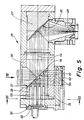
- FIG. 5 to 7 show an alternative embodiment of a processing optics 25 in which a plurality of bores distributed in a grid pattern on the mirror surfaces 36 and 37 of the mirrors instead of the slots 49 present in the exemplary embodiment described above, for measuring the beam position, the beam diameter and the reflected back laser beams are provided.
- the bores are arranged exclusively in the deflecting mirror 26, specifically as Through bores 55 running parallel to the longitudinal center line thereof and through bores 56 running transversely thereto.
- the through bores have a very small diameter to the mirror surface 37, namely only about 0.5 mm.
- the diameters of the through bores 55 and 56 increase in steps.
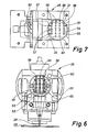
- FIG. 7 shows the grid according to which the through bores 55 and 26 are distributed over the mirror surface 37 of the deflecting mirror 26. Accordingly, a total of 24 through bores are provided here, namely 12 (horizontal) through bores 55 and also 12 (vertical) through bores 56. These are on four horizontal rows 54 and seven vertical rows 57 and 58 over a reduced number of through bores 55 and 56 have. 7 by partial blackening of the through bores 55 and 56 indicates whether these are combined to form a vertical or horizontal measuring string. Accordingly, the un-blackened through holes 55 and 56 form the horizontal measuring strands, while the semi-blackened through holes 55 and 56 form the vertical measuring strands. From this it can be seen that three vertical measuring strands and four horizontal measuring strands are provided in the present exemplary embodiment.
- the horizontal through bores 55 are continued in some areas in the cover 33 and are connected by a bore 60 directed transversely thereto.
- This is used to accommodate one or more suitable detectors, for example resistance thermometers made of wire. These can either run continuously over the entire measuring strand (row 58), but can also be divided in the middle, so that each measuring strand (row 58) two detectors 59 in the form of resistance thermometers are assigned.
- the detectors 61 can be designed in an analogous manner, namely also as resistance thermometers, which are accommodated in bores 62 running transversely to the vertical through bores 56 in the housing 30 of the processing optics 25.
- the diameter and the position of the incoming laser beam at the deflecting mirror 26 are measured with the aid of the vertical through holes 56, while the position, the power - and possibly the diameter - of the laser light reflected back from the workpiece 29 are measured with the aid of the horizontal through holes 55.
- the evaluation of the measurement results obtained at the detectors 59 and 61 takes place here in a manner similar to that in the exemplary embodiment described above with (detection) slots 49 arranged in the mirrors (deflection mirror 26; focusing mirror 27).
- the through holes 55 and 56 can also be distributed in this embodiment of the processing optics 55 according to the invention on the deflecting mirror 26 and the focusing mirror 27, so that each mirror would then only have either vertical or horizontal through holes.
- FIGS. 8 to 11 show an exemplary embodiment of the processing optics 25 according to the invention, in which sensors 63 which absorb directly on the mirror surface 37 of the deflecting mirror 26 are arranged.
- the sensors 63 can be designed as wire-shaped resistance thermometers.
- the course of the sensors 63 arranged here on the mirror surface 37 of the deflecting mirror 26 can be seen in FIG. 9. Accordingly, four sensors 63 made of U-shaped coiled wire are arranged so as to run radially evenly distributed on the mirror surface 37 without meeting in the center 50 of the mirror surface 37.
- the 10 shows the attachment of the sensors 63 on the mirror surface 37 of the deflecting mirror 26.
- approximately semicircular recesses 64 for the sensors 63 are arranged on the mirror surface 37, the majority of which are filled with an insulator 65 by in each case a wire for the sensor 63 being embedded such that the mirror surface 37 remains flat despite the sensors 63 arranged thereon .
- the insulator 65 preferably consists of an adhesive for permanently fixing the wire for the sensors 63 in the recesses 64 of the deflection mirror 26.
- FIG. 11 An alternative embodiment of the attachment of the sensors 63 on the mirror surface 37 of the deflecting mirror 26 is shown in FIG. 11.
- the sensors 63 - which can also have the course shown in FIG. 9 - are raised on the mirror surface 37.
- the sensors 63 are formed from a thin, layer-shaped conductor which is connected to the mirror surface 37 by an insulation layer 66.
- Such sensors 63 can be produced, for example, by vapor deposition on the mirror surface 37 of the deflecting mirror 26.
Landscapes
- Physics & Mathematics (AREA)
- Optics & Photonics (AREA)
- Engineering & Computer Science (AREA)
- Plasma & Fusion (AREA)
- Mechanical Engineering (AREA)
- Laser Beam Processing (AREA)
- Photometry And Measurement Of Optical Pulse Characteristics (AREA)
Applications Claiming Priority (2)
| Application Number | Priority Date | Filing Date | Title |
|---|---|---|---|
| DE19863623409 DE3623409A1 (de) | 1986-07-11 | 1986-07-11 | Verfahren zur ueberwachung des bearbeitungsprozesses mit einer hochleistungsenergiequelle, insbesondere einem laser, und bearbeitungsoptik zur durchfuehrung desselben |
| DE3623409 | 1986-07-11 |
Publications (3)
| Publication Number | Publication Date |
|---|---|
| EP0252268A2 true EP0252268A2 (fr) | 1988-01-13 |
| EP0252268A3 EP0252268A3 (en) | 1989-02-01 |
| EP0252268B1 EP0252268B1 (fr) | 1992-03-25 |
Family
ID=6304957
Family Applications (1)
| Application Number | Title | Priority Date | Filing Date |
|---|---|---|---|
| EP87107712A Expired - Lifetime EP0252268B1 (fr) | 1986-07-11 | 1987-05-27 | Procédé pour la surveillance de source d'énergie d'usinage, en particulier d'un laser, et optique d'usinage pour la réalisation de celui-ci |
Country Status (4)
| Country | Link |
|---|---|
| US (1) | US4772772A (fr) |
| EP (1) | EP0252268B1 (fr) |
| JP (1) | JPS6330191A (fr) |
| DE (2) | DE3623409A1 (fr) |
Cited By (7)
| Publication number | Priority date | Publication date | Assignee | Title |
|---|---|---|---|---|
| EP0464213A1 (fr) * | 1990-01-19 | 1992-01-08 | Fanuc Ltd. | Procede de decoupage au laser |
| FR2682476A1 (fr) * | 1991-10-10 | 1993-04-16 | Cheval Freres Sa | Procede pour la detection et la mesure de l'energie emise par une source laser et dispositif pour sa mise en óoeuvre. |
| WO1994026459A1 (fr) * | 1993-05-19 | 1994-11-24 | Fraunhofer-Gesellschaft zur Förderung der angewandten Forschung e.V. | Procede permettant de travailler des materiaux par rayonnement emis par des diodes |
| US6791057B1 (en) * | 1998-11-12 | 2004-09-14 | Fraunhofer-Gesellschaft Zur Forderung Der Angewandten Forschung E.V. | Method and device for machining workpieces using high-energy radiation |
| WO2007124765A1 (fr) | 2006-04-28 | 2007-11-08 | Trumpf Werkzeugmaschinen Gmbh + Co. Kg | Machine d'usinage au laser et procédé d'usinage au laser |
| EP1457286A3 (fr) * | 2003-03-11 | 2007-12-19 | Erlas Erlanger Lasertechnik GmbH | Procédé, dispositif de surveillance et leur utilisation et dispositif d'usinage laser avec surveillance de défaut d'un composant optique |
| DE102012100721B3 (de) * | 2012-01-30 | 2013-04-11 | Trumpf Werkzeugmaschinen Gmbh + Co. Kg | Verfahren zum Regeln eines Laserschneidprozesses und Laserschneidmaschine |
Families Citing this family (15)
| Publication number | Priority date | Publication date | Assignee | Title |
|---|---|---|---|---|
| US5004338A (en) * | 1989-03-01 | 1991-04-02 | Morrow Clifford E | Method and apparatus for attenuation and measurement of laser power at the end of a laser guide |
| DE4006622C2 (de) * | 1990-03-02 | 1993-10-14 | Fraunhofer Ges Forschung | Vorrichtung zum Überwachen von mit Laserstrahlung bearbeiteten Werkstücken |
| US5045669A (en) * | 1990-03-02 | 1991-09-03 | General Electric Company | Method and apparatus for optically/acoustically monitoring laser materials processing |
| US5026979A (en) * | 1990-03-05 | 1991-06-25 | General Electric Company | Method and apparatus for optically monitoring laser materials processing |
| US5159402A (en) * | 1990-03-26 | 1992-10-27 | General Electric Company | Optical sensor safety system for monitoring laser crystals and optical components |
| DE4212652C2 (de) * | 1992-04-15 | 1994-06-30 | Weidmueller Interface | Laserbearbeitungskopf mit induktivem Abstandssensor |
| DE19630437C2 (de) * | 1996-07-27 | 2003-04-03 | Jurca Optoelektronik Gmbh | Detektorvorrichtung |
| SE9701710L (sv) * | 1997-05-07 | 1998-09-14 | Inst Verkstadstek Forsk Ivf | Anordning för detektering och beräkning av en laserstråles fokusläge, form och effektfördelning |
| US5991319A (en) * | 1997-11-21 | 1999-11-23 | Trw Inc. | Mirror failure detector for high power lasers |
| US20040034599A1 (en) * | 2001-06-01 | 2004-02-19 | Pietro Ferrero | Method and device for the robot-controlled cutting of workpieces to be assembled by means of laser radiation |
| US6987240B2 (en) * | 2002-04-18 | 2006-01-17 | Applied Materials, Inc. | Thermal flux processing by scanning |
| ATE519560T1 (de) | 2004-10-20 | 2011-08-15 | Trumpf Werkzeugmaschinen Gmbh | Optisches element eines laserbearbeitungskopfs |
| FR2877591B1 (fr) * | 2004-11-09 | 2007-06-08 | Commissariat Energie Atomique | Systeme et procede de production de poudres nanometriques ou sub-micrometriques en flux continu sous l'action d'une pyrolyse laser |
| EP2409808A1 (fr) * | 2010-07-22 | 2012-01-25 | Bystronic Laser AG | Machine de traitement au laser |
| EP2883647B1 (fr) | 2013-12-12 | 2019-05-29 | Bystronic Laser AG | Procédé de configuration d'un dispositif d'usinage au laser |
Citations (4)
| Publication number | Priority date | Publication date | Assignee | Title |
|---|---|---|---|---|
| DE2914216A1 (de) * | 1978-04-20 | 1979-10-31 | Halle Feinmech Werke Veb | Anordnung zur stabilisierung einer laserstrahlung |
| EP0156231A2 (fr) * | 1984-03-26 | 1985-10-02 | BIAS Forschungs- und Entwicklungslabor für angewandte Strahltechnik | Dispositif pour traiter des pièces d'oeuvre par faisceau d'énergie à puissance volumique très élevée, notamment un faisceau laser de laser à CO2 |
| EP0168351A1 (fr) * | 1984-07-10 | 1986-01-15 | Lasarray Holding Ag | Générateur laser de motifs et procédé pour son emploi |
| CH656568A5 (de) * | 1980-09-02 | 1986-07-15 | Amada Co Ltd | Verfahren und vorrichtung zur detektion des brennpunktes eines laserstrahles in einer laserwerkzeugmaschine. |
Family Cites Families (16)
| Publication number | Priority date | Publication date | Assignee | Title |
|---|---|---|---|---|
| DE140117C (fr) * | ||||
| US3441973A (en) * | 1967-09-19 | 1969-05-06 | Albert Turk | Mop wringer with gear driven rolls |
| US4019381A (en) * | 1976-01-12 | 1977-04-26 | The United States Of America As Represented By The Secretary Of The Army | Transparent optical power meter |
| DD140117B1 (de) * | 1978-12-27 | 1981-07-29 | Manfred Poehler | Anordnung zur praezisionsmaterialbearbeitung mittels laserstrahlen |
| DE2949564C2 (de) * | 1979-12-10 | 1981-11-12 | Gerhard Dr. 8012 Ottobrunn Busse | Einrichtung zur Messung der Strahlungsleistung von leisuntgsmodulierten optischen Sendern, insbesondere von Lasern |
| US4262198A (en) * | 1979-07-30 | 1981-04-14 | California Institute Of Technology | Broadband optical radiation detector |
| JPS57134148A (en) * | 1981-02-16 | 1982-08-19 | Olympus Optical Co | Detector of leading end output of laser knife |
| JPS5952035B2 (ja) * | 1981-06-16 | 1984-12-17 | 株式会社東芝 | レ−ザ加工装置 |
| JPS58205689A (ja) * | 1982-05-24 | 1983-11-30 | Hitachi Ltd | レ−ザビ−ムの反射光量検出方法 |
| JPS5927793A (ja) * | 1982-08-09 | 1984-02-14 | Toshiba Corp | レ−ザ光光路保護カバ− |
| DE8227494U1 (de) * | 1982-09-30 | 1983-02-17 | Arnold, Peter, Dr., 8000 München | Vorrichtung zur messung der intensitaet eines laserstrahls |
| JPS5964188A (ja) * | 1982-10-05 | 1984-04-12 | Asahi Optical Co Ltd | レ−ザ−光用ビ−ムベンダ−位置検出装置 |
| DE3339318C2 (de) * | 1983-10-29 | 1995-05-24 | Trumpf Gmbh & Co | Laser-Bearbeitungsmaschine |
| JPS60102290A (ja) * | 1983-11-09 | 1985-06-06 | Hitachi Ltd | レ−ザ加工装置 |
| DD227364A1 (de) * | 1984-10-22 | 1985-09-18 | Univ Schiller Jena | Anordnung zur steuerung von verfahrensparametern bei der werkstoffbearbeitung mittels laserstrahlen |
| US4648400A (en) * | 1985-05-06 | 1987-03-10 | Rts Laboratories, Inc. | Ophthalmic surgery system |
-
1986
- 1986-07-11 DE DE19863623409 patent/DE3623409A1/de not_active Withdrawn
-
1987
- 1987-05-27 DE DE8787107712T patent/DE3777702D1/de not_active Expired - Lifetime
- 1987-05-27 EP EP87107712A patent/EP0252268B1/fr not_active Expired - Lifetime
- 1987-07-01 US US07/068,302 patent/US4772772A/en not_active Expired - Fee Related
- 1987-07-09 JP JP62169932A patent/JPS6330191A/ja active Pending
Patent Citations (4)
| Publication number | Priority date | Publication date | Assignee | Title |
|---|---|---|---|---|
| DE2914216A1 (de) * | 1978-04-20 | 1979-10-31 | Halle Feinmech Werke Veb | Anordnung zur stabilisierung einer laserstrahlung |
| CH656568A5 (de) * | 1980-09-02 | 1986-07-15 | Amada Co Ltd | Verfahren und vorrichtung zur detektion des brennpunktes eines laserstrahles in einer laserwerkzeugmaschine. |
| EP0156231A2 (fr) * | 1984-03-26 | 1985-10-02 | BIAS Forschungs- und Entwicklungslabor für angewandte Strahltechnik | Dispositif pour traiter des pièces d'oeuvre par faisceau d'énergie à puissance volumique très élevée, notamment un faisceau laser de laser à CO2 |
| EP0168351A1 (fr) * | 1984-07-10 | 1986-01-15 | Lasarray Holding Ag | Générateur laser de motifs et procédé pour son emploi |
Non-Patent Citations (1)
| Title |
|---|
| IBM TECHNICAL DISCLOSURE BULLETIN, Band 24, Nr. 9, Februar 1982, Seiten 4691,4692, New York, US; H.E. KLAUSER: "Closed-loop laser control system" * |
Cited By (10)
| Publication number | Priority date | Publication date | Assignee | Title |
|---|---|---|---|---|
| EP0464213A1 (fr) * | 1990-01-19 | 1992-01-08 | Fanuc Ltd. | Procede de decoupage au laser |
| EP0464213B1 (fr) * | 1990-01-19 | 1995-07-19 | Fanuc Ltd. | Procede de decoupage au laser |
| FR2682476A1 (fr) * | 1991-10-10 | 1993-04-16 | Cheval Freres Sa | Procede pour la detection et la mesure de l'energie emise par une source laser et dispositif pour sa mise en óoeuvre. |
| WO1994026459A1 (fr) * | 1993-05-19 | 1994-11-24 | Fraunhofer-Gesellschaft zur Förderung der angewandten Forschung e.V. | Procede permettant de travailler des materiaux par rayonnement emis par des diodes |
| US5705788A (en) * | 1993-05-19 | 1998-01-06 | Fraunhofer-Gesellschaft Zur Forderung Der Angewandten Forschung E.V. | Process for treatment of materials with diode radiation |
| US6791057B1 (en) * | 1998-11-12 | 2004-09-14 | Fraunhofer-Gesellschaft Zur Forderung Der Angewandten Forschung E.V. | Method and device for machining workpieces using high-energy radiation |
| EP1457286A3 (fr) * | 2003-03-11 | 2007-12-19 | Erlas Erlanger Lasertechnik GmbH | Procédé, dispositif de surveillance et leur utilisation et dispositif d'usinage laser avec surveillance de défaut d'un composant optique |
| WO2007124765A1 (fr) | 2006-04-28 | 2007-11-08 | Trumpf Werkzeugmaschinen Gmbh + Co. Kg | Machine d'usinage au laser et procédé d'usinage au laser |
| CN101432093B (zh) * | 2006-04-28 | 2012-06-20 | 通快机床两合公司 | 激光加工设备和激光加工方法 |
| DE102012100721B3 (de) * | 2012-01-30 | 2013-04-11 | Trumpf Werkzeugmaschinen Gmbh + Co. Kg | Verfahren zum Regeln eines Laserschneidprozesses und Laserschneidmaschine |
Also Published As
| Publication number | Publication date |
|---|---|
| JPS6330191A (ja) | 1988-02-08 |
| EP0252268B1 (fr) | 1992-03-25 |
| DE3777702D1 (de) | 1992-04-30 |
| DE3623409A1 (de) | 1988-01-21 |
| EP0252268A3 (en) | 1989-02-01 |
| US4772772A (en) | 1988-09-20 |
Similar Documents
| Publication | Publication Date | Title |
|---|---|---|
| EP0252268B1 (fr) | Procédé pour la surveillance de source d'énergie d'usinage, en particulier d'un laser, et optique d'usinage pour la réalisation de celui-ci | |
| DE3739862C2 (fr) | ||
| DE10113518B4 (de) | Verfahren zur Messung des Verschmutzungsgrades eines Schutzglases eines Laserbearbeitungskopfs sowie Laserbearbeitungsanlage zur Durchführung des Verfahrens | |
| DE69703697T2 (de) | Laservorrichtung | |
| EP0781187B1 (fr) | Procede et dispositif d'usinage de materiaux avec un rayonnement laser inducteur de plasma | |
| DE3246290C2 (fr) | ||
| EP0215734B1 (fr) | Procédé et équipement pour l'ajustement fin de rayon laser | |
| DE3045319A1 (de) | Vorrichtung zum messen bestimmter ausgewaehlter eigenschaften einer bewegten bahn | |
| EP0143282A2 (fr) | Procédé pour la mesure sans contact de la température d'un objet par mesure du rayonnement sans influence du degré d'émissivité | |
| DE102010015023B4 (de) | Verfahren und Vorrichtung zur Qualitätssicherung und Prozesskontrolle bei der Laserbearbeitung von Werkstücken | |
| DE3933057C2 (fr) | ||
| WO2019115449A1 (fr) | Procédé et unité d'ajustement servant à ajuster de manière automatisée un rayon laser d'un machine d'usinage par laser, ainsi que machine d'usinage par laser comprenant l'unité d'ajustement | |
| DE3532047C2 (fr) | ||
| DE69300432T2 (de) | Laservorrichtung, insbesondere Laser-Roboter, mit einem Fokussierkopf, der mit Sensoren für die Qualitätsbestimmung des Prozesses in einem automatischen Produktionssystem ausgestattet ist. | |
| EP1310782B1 (fr) | Procédé et dispositif de saisie d'informations pour le contrôle d'un dispositif laser | |
| DE4006622C2 (de) | Vorrichtung zum Überwachen von mit Laserstrahlung bearbeiteten Werkstücken | |
| EP1172635B1 (fr) | Dispositif optique de mesure de positions | |
| DE4341417A1 (de) | Lichtleiter-Endabschlußvorrichtung | |
| DE3726466A1 (de) | Werkstueckbearbeitungsvorrichtung | |
| EP1448962B1 (fr) | Procede et dispositif d'analyse et de controle de la repartition de l'intensite lumineuse sur la section transversale d'un rayon lumineux | |
| DE10125454A1 (de) | Gerät zur Röntgenanalyse mit einem Mehrschichtspiegel und einem Ausgangskollimator | |
| WO2018019809A1 (fr) | Procédé d'assemblage et dispositif d'assemblage pour la réalisation du procédé d'assemblage | |
| EP0674965B1 (fr) | Procédé de surveillance de la profondeur de soudage dans les pièces étant soudées au faisceau laser | |
| DE4006618C2 (de) | Vorrichtung zur Auskoppelung einer Meßstrahlung aus einem Laserstrahl | |
| DE8710866U1 (de) | Werkstückbearbeitungsvorrichtung |
Legal Events
| Date | Code | Title | Description |
|---|---|---|---|
| PUAI | Public reference made under article 153(3) epc to a published international application that has entered the european phase |
Free format text: ORIGINAL CODE: 0009012 |
|
| AK | Designated contracting states |
Kind code of ref document: A2 Designated state(s): BE DE FR GB IT NL SE |
|
| PUAL | Search report despatched |
Free format text: ORIGINAL CODE: 0009013 |
|
| AK | Designated contracting states |
Kind code of ref document: A3 Designated state(s): BE DE FR GB IT NL SE |
|
| 17P | Request for examination filed |
Effective date: 19890107 |
|
| 17Q | First examination report despatched |
Effective date: 19890605 |
|
| GRAA | (expected) grant |
Free format text: ORIGINAL CODE: 0009210 |
|
| AK | Designated contracting states |
Kind code of ref document: B1 Designated state(s): BE DE FR GB IT NL SE |
|
| REF | Corresponds to: |
Ref document number: 3777702 Country of ref document: DE Date of ref document: 19920430 |
|
| GBT | Gb: translation of ep patent filed (gb section 77(6)(a)/1977) | ||
| ITF | It: translation for a ep patent filed | ||
| ET | Fr: translation filed | ||
| PLBE | No opposition filed within time limit |
Free format text: ORIGINAL CODE: 0009261 |
|
| STAA | Information on the status of an ep patent application or granted ep patent |
Free format text: STATUS: NO OPPOSITION FILED WITHIN TIME LIMIT |
|
| 26N | No opposition filed | ||
| PGFP | Annual fee paid to national office [announced via postgrant information from national office to epo] |
Ref country code: SE Payment date: 19930517 Year of fee payment: 7 |
|
| PGFP | Annual fee paid to national office [announced via postgrant information from national office to epo] |
Ref country code: NL Payment date: 19930531 Year of fee payment: 7 |
|
| PGFP | Annual fee paid to national office [announced via postgrant information from national office to epo] |
Ref country code: BE Payment date: 19930628 Year of fee payment: 7 |
|
| PGFP | Annual fee paid to national office [announced via postgrant information from national office to epo] |
Ref country code: FR Payment date: 19940511 Year of fee payment: 8 |
|
| PGFP | Annual fee paid to national office [announced via postgrant information from national office to epo] |
Ref country code: GB Payment date: 19940517 Year of fee payment: 8 |
|
| PGFP | Annual fee paid to national office [announced via postgrant information from national office to epo] |
Ref country code: DE Payment date: 19940526 Year of fee payment: 8 |
|
| PG25 | Lapsed in a contracting state [announced via postgrant information from national office to epo] |
Ref country code: SE Effective date: 19940528 |
|
| PG25 | Lapsed in a contracting state [announced via postgrant information from national office to epo] |
Ref country code: BE Effective date: 19940531 |
|
| BERE | Be: lapsed |
Owner name: BIAS FORSCHUNGS- UND ENTWICKLUNGSLABOR FUR ANGEWA Effective date: 19940531 |
|
| PG25 | Lapsed in a contracting state [announced via postgrant information from national office to epo] |
Ref country code: NL Effective date: 19941201 |
|
| NLV4 | Nl: lapsed or anulled due to non-payment of the annual fee | ||
| EUG | Se: european patent has lapsed |
Ref document number: 87107712.9 Effective date: 19941210 |
|
| EUG | Se: european patent has lapsed |
Ref document number: 87107712.9 |
|
| PG25 | Lapsed in a contracting state [announced via postgrant information from national office to epo] |
Ref country code: GB Effective date: 19950527 |
|
| GBPC | Gb: european patent ceased through non-payment of renewal fee |
Effective date: 19950527 |
|
| PG25 | Lapsed in a contracting state [announced via postgrant information from national office to epo] |
Ref country code: DE Effective date: 19960201 |
|
| PG25 | Lapsed in a contracting state [announced via postgrant information from national office to epo] |
Ref country code: FR Effective date: 19960229 |
|
| REG | Reference to a national code |
Ref country code: FR Ref legal event code: ST |
|
| REG | Reference to a national code |
Ref country code: FR Ref legal event code: ST |
|
| PG25 | Lapsed in a contracting state [announced via postgrant information from national office to epo] |
Ref country code: IT Free format text: LAPSE BECAUSE OF NON-PAYMENT OF DUE FEES Effective date: 20050527 |