EP0249972A2 - Pièce d'insertion susceptible d'être enroulée pour manchon de câble et fabrication de celle-ci - Google Patents
Pièce d'insertion susceptible d'être enroulée pour manchon de câble et fabrication de celle-ci Download PDFInfo
- Publication number
- EP0249972A2 EP0249972A2 EP87108723A EP87108723A EP0249972A2 EP 0249972 A2 EP0249972 A2 EP 0249972A2 EP 87108723 A EP87108723 A EP 87108723A EP 87108723 A EP87108723 A EP 87108723A EP 0249972 A2 EP0249972 A2 EP 0249972A2
- Authority
- EP
- European Patent Office
- Prior art keywords
- cable sleeve
- sleeve insert
- insert according
- windable
- layers
- Prior art date
- Legal status (The legal status is an assumption and is not a legal conclusion. Google has not performed a legal analysis and makes no representation as to the accuracy of the status listed.)
- Granted
Links
- 238000004519 manufacturing process Methods 0.000 title claims description 7
- 239000002131 composite material Substances 0.000 claims abstract description 27
- 239000011324 bead Substances 0.000 claims abstract description 16
- 238000005520 cutting process Methods 0.000 claims abstract description 8
- 239000000463 material Substances 0.000 claims abstract description 7
- 239000010410 layer Substances 0.000 claims description 56
- 239000010408 film Substances 0.000 claims description 17
- 239000013039 cover film Substances 0.000 claims description 10
- 239000012790 adhesive layer Substances 0.000 claims description 9
- 239000004698 Polyethylene Substances 0.000 claims description 5
- 210000004907 gland Anatomy 0.000 claims description 5
- -1 polyethylene Polymers 0.000 claims description 5
- 229920000573 polyethylene Polymers 0.000 claims description 5
- 229910052782 aluminium Inorganic materials 0.000 claims description 4
- XAGFODPZIPBFFR-UHFFFAOYSA-N aluminium Chemical compound [Al] XAGFODPZIPBFFR-UHFFFAOYSA-N 0.000 claims description 4
- 229920000728 polyester Polymers 0.000 claims description 4
- 239000000853 adhesive Substances 0.000 claims description 2
- 230000001070 adhesive effect Effects 0.000 claims description 2
- 238000000034 method Methods 0.000 claims 1
- 230000002093 peripheral effect Effects 0.000 claims 1
- 230000006978 adaptation Effects 0.000 description 5
- WXZMFSXDPGVJKK-UHFFFAOYSA-N pentaerythritol Chemical compound OCC(CO)(CO)CO WXZMFSXDPGVJKK-UHFFFAOYSA-N 0.000 description 3
- 239000004033 plastic Substances 0.000 description 3
- 229920003023 plastic Polymers 0.000 description 3
- 239000005020 polyethylene terephthalate Substances 0.000 description 3
- 229920000139 polyethylene terephthalate Polymers 0.000 description 3
- 238000003825 pressing Methods 0.000 description 3
- 239000011888 foil Substances 0.000 description 2
- 239000002313 adhesive film Substances 0.000 description 1
- 229910052751 metal Inorganic materials 0.000 description 1
- 239000002184 metal Substances 0.000 description 1
- 238000007789 sealing Methods 0.000 description 1
- 230000007704 transition Effects 0.000 description 1
Images

Classifications
-
- H—ELECTRICITY
- H02—GENERATION; CONVERSION OR DISTRIBUTION OF ELECTRIC POWER
- H02G—INSTALLATION OF ELECTRIC CABLES OR LINES, OR OF COMBINED OPTICAL AND ELECTRIC CABLES OR LINES
- H02G15/00—Cable fittings
- H02G15/08—Cable junctions
- H02G15/18—Cable junctions protected by sleeves, e.g. for communication cable
- H02G15/1806—Heat shrinkable sleeves
-
- Y—GENERAL TAGGING OF NEW TECHNOLOGICAL DEVELOPMENTS; GENERAL TAGGING OF CROSS-SECTIONAL TECHNOLOGIES SPANNING OVER SEVERAL SECTIONS OF THE IPC; TECHNICAL SUBJECTS COVERED BY FORMER USPC CROSS-REFERENCE ART COLLECTIONS [XRACs] AND DIGESTS
- Y10—TECHNICAL SUBJECTS COVERED BY FORMER USPC
- Y10T—TECHNICAL SUBJECTS COVERED BY FORMER US CLASSIFICATION
- Y10T156/00—Adhesive bonding and miscellaneous chemical manufacture
- Y10T156/10—Methods of surface bonding and/or assembly therefor
- Y10T156/1002—Methods of surface bonding and/or assembly therefor with permanent bending or reshaping or surface deformation of self sustaining lamina
- Y10T156/1025—Methods of surface bonding and/or assembly therefor with permanent bending or reshaping or surface deformation of self sustaining lamina to form undulated to corrugated sheet and securing to base with parts of shaped areas out of contact
-
- Y—GENERAL TAGGING OF NEW TECHNOLOGICAL DEVELOPMENTS; GENERAL TAGGING OF CROSS-SECTIONAL TECHNOLOGIES SPANNING OVER SEVERAL SECTIONS OF THE IPC; TECHNICAL SUBJECTS COVERED BY FORMER USPC CROSS-REFERENCE ART COLLECTIONS [XRACs] AND DIGESTS
- Y10—TECHNICAL SUBJECTS COVERED BY FORMER USPC
- Y10T—TECHNICAL SUBJECTS COVERED BY FORMER US CLASSIFICATION
- Y10T428/00—Stock material or miscellaneous articles
- Y10T428/13—Hollow or container type article [e.g., tube, vase, etc.]
- Y10T428/1352—Polymer or resin containing [i.e., natural or synthetic]
- Y10T428/1355—Elemental metal containing [e.g., substrate, foil, film, coating, etc.]
- Y10T428/1359—Three or more layers [continuous layer]
-
- Y—GENERAL TAGGING OF NEW TECHNOLOGICAL DEVELOPMENTS; GENERAL TAGGING OF CROSS-SECTIONAL TECHNOLOGIES SPANNING OVER SEVERAL SECTIONS OF THE IPC; TECHNICAL SUBJECTS COVERED BY FORMER USPC CROSS-REFERENCE ART COLLECTIONS [XRACs] AND DIGESTS
- Y10—TECHNICAL SUBJECTS COVERED BY FORMER USPC
- Y10T—TECHNICAL SUBJECTS COVERED BY FORMER US CLASSIFICATION
- Y10T428/00—Stock material or miscellaneous articles
- Y10T428/13—Hollow or container type article [e.g., tube, vase, etc.]
- Y10T428/1352—Polymer or resin containing [i.e., natural or synthetic]
- Y10T428/139—Open-ended, self-supporting conduit, cylinder, or tube-type article
- Y10T428/1393—Multilayer [continuous layer]
-
- Y—GENERAL TAGGING OF NEW TECHNOLOGICAL DEVELOPMENTS; GENERAL TAGGING OF CROSS-SECTIONAL TECHNOLOGIES SPANNING OVER SEVERAL SECTIONS OF THE IPC; TECHNICAL SUBJECTS COVERED BY FORMER USPC CROSS-REFERENCE ART COLLECTIONS [XRACs] AND DIGESTS
- Y10—TECHNICAL SUBJECTS COVERED BY FORMER USPC
- Y10T—TECHNICAL SUBJECTS COVERED BY FORMER US CLASSIFICATION
- Y10T428/00—Stock material or miscellaneous articles
- Y10T428/24—Structurally defined web or sheet [e.g., overall dimension, etc.]
- Y10T428/24479—Structurally defined web or sheet [e.g., overall dimension, etc.] including variation in thickness
- Y10T428/2457—Parallel ribs and/or grooves
-
- Y—GENERAL TAGGING OF NEW TECHNOLOGICAL DEVELOPMENTS; GENERAL TAGGING OF CROSS-SECTIONAL TECHNOLOGIES SPANNING OVER SEVERAL SECTIONS OF THE IPC; TECHNICAL SUBJECTS COVERED BY FORMER USPC CROSS-REFERENCE ART COLLECTIONS [XRACs] AND DIGESTS
- Y10—TECHNICAL SUBJECTS COVERED BY FORMER USPC
- Y10T—TECHNICAL SUBJECTS COVERED BY FORMER US CLASSIFICATION
- Y10T428/00—Stock material or miscellaneous articles
- Y10T428/24—Structurally defined web or sheet [e.g., overall dimension, etc.]
- Y10T428/24628—Nonplanar uniform thickness material
- Y10T428/24669—Aligned or parallel nonplanarities
- Y10T428/24694—Parallel corrugations
- Y10T428/24702—Parallel corrugations with locally deformed crests or intersecting series of corrugations
Definitions
- the invention relates to a windable cable sleeve insert made of a smooth and a corrugated composite layer, each consisting of several material layers, these composite layers being arranged one above the other.
- a windable cable sleeve insert for a shrinkable cable sleeve is known, in which two superimposed composite layers are arranged.
- One of these composite layers has a corrugated shape and covers the entire area to be covered, while the second composite layer has a smooth shape and is only applied in the middle area on the first composite layer between the two adjustable edge regions of the cable sleeve insert.
- This composite layer applied in the middle area increases the strength and the heat protection, while the edge areas with the exposed corrugation serve to adapt between the differences in diameter.
- a special cable sleeve insert must be available for each type of sleeve, which must be defined in terms of diameter and length.
- Another object of the invention is to provide a method for producing such a cable sleeve insert. This object is achieved according to the features described in claim 14.
- the advantages of the cable sleeve insert compared to the prior art now consist primarily in the fact that only a single large area can be produced from the composite films sufficient for the requirements.
- This large area can be provided in pieces or in rolled up form, only the width of the large area being predetermined by the possible manufacturing width.
- the dimensions can be chosen freely that, for example, unequal adapters are possible if, for example, cables with unequal diameters are introduced. From these examples it can be seen that this cable sleeve insert according to the invention can be optimally adapted in a universal manner for all possible applications.
- the determining relationships of the cable sleeve insert KE can be seen in a plan view of the corrugated film WF consisting of a composite layer.
- This corrugated foil WF is firmly attached to the underlying cover foil, which is not visible here, the dimensions shown here already being intended to correspond to a complete cable sleeve insert KE.
- the corrugation extends, as with all cable sleeve inserts KE of the invention, in the axial direction of the object to be wrapped later, for example the cable, and is preferably directed inward when wrapping tet, so that the smooth cover film DF is visible to the outside. When the shrinkable covering is shrunk on, a smooth surface results.
- an adaptation must take place between these different diameters, which is carried out by pressing the two outer adaptation regions together. This pressing together is facilitated by a defined breaking edge along beads S which are introduced into the corrugation W of the corrugated film WF. This is done with any folding tool that may be heated so that the plastic layers in the composite layer are easier to deform. These beads S can be introduced at any point, so that the lengths of the adaptation areas AB can be determined and adapted as desired.
- FIG. 2 shows a transverse view of the cut cable sleeve insert KE, whereby the structure of the two composite layers, the cover film DF and the corrugated film WF becomes clear.
- the mutual adhesion expediently takes place by means of adhesive films of the two composite layers, which lie opposite one another and are glued or fused together along the common contact lines BL.
- FIG. 3 shows the view indicated in FIG. 1 in the area of a transverse bead S. It is clear that the corrugated sheet WF applied to the smooth cover sheet DF is dented, so that the corrugation W is weakened or interrupted in the direction of this bead S. is. In this way, the cable sleeve insert can be easily bent along this bead S and thus adjusted accordingly.
- the composite film designed as a cover film DF consists, for example, of three individual layers, an adhesive layer HS, a permeation protection layer PS and a heat protection layer WS. This also applies accordingly to the corrugated film WF, the number and the thickness of the individual layers being different.
- a fusible plastic preferably polyethylene, is used as the adhesive layer HS, the layer thickness preferably being between 15 and 40 ⁇ m.
- the permeation protection layer PS is preferably made of metal, for example aluminum, and is between 15 to 40 ⁇ m thick for the cover film DF and 30 to 60 ⁇ m thick for the corrugated film WF.
- the overlying thermal protection layer WS in turn consists of a plastic, preferably polyester (PETP) and is applied in a thickness of 10 to 80 ⁇ m.
- a typical exemplary embodiment for a cable sleeve insert has the following composite layers: Cover film: adhesive layer HS made of a 25 ⁇ m thick layer of polyethylene Permeation protection layer PS made of a 20 ⁇ m thick layer of aluminum Thermal protection layer WS made of a 12 ⁇ m thick layer of polyester (PETP)
- Corrugated film adhesive layer HS made of a 25 ⁇ m thick layer of polyethylene Permeation protection layer PS made of a 35 ⁇ m thick layer of aluminum Thermal protection layer WS made of a 75 ⁇ m thick layer of polyester (PETP)
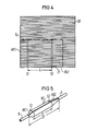
- FIG. 4 now shows the universal adaptability of the cable sleeve insert KE according to the invention.
- a large area GF has to be created from the two composite layers DF and WF that are already adhering together, from or from which the cutting area ZF that is just required is cut or cut.
- the large area GF to be provided is only determined by the manufacturing conditions, that is to say by the possible dimensions of the manufacturing machines.
- This large area GF which is ready to be built, is then stored either as a flat part or in a rolled-up form until the appropriate cut is made if necessary. This eliminates the production and warehousing of different types.
- the length of the middle part for the cable sleeve insert KE can also be freely determined by appropriate choice of the distance A of the transverse beads S1 and S2, with the additional possibility of making the adjustment areas AB1 and AB2 unequal in accordance with the existing conditions to choose in length. In this way, an optimal adaptation to different diameter transitions on both sides is made possible.
- FIG. 5 shows schematically a cable sleeve insert KE produced in accordance with the invention, which is wound up, for example, over a cable splice with the inserted cables K and which is pressed along the inserted beads S1 and S2 by pressing the two outer ends of the cutting surface ZF onto the two diameters of the two cables K is angled and thereby adapted.
- the two adaptation areas AB1 and AB2 are not of the same length.
- the cable gland insert KE provides the desired support over the entire area of the cable sleeve.
Landscapes
- Insulated Conductors (AREA)
- Insulating Bodies (AREA)
- Cable Accessories (AREA)
- Stereo-Broadcasting Methods (AREA)
- Details Of Indoor Wiring (AREA)
- Ropes Or Cables (AREA)
- Processing Of Terminals (AREA)
Priority Applications (1)
| Application Number | Priority Date | Filing Date | Title |
|---|---|---|---|
| AT87108723T ATE56842T1 (de) | 1986-06-19 | 1987-06-16 | Wickelbare kabelmuffeneinlage und herstellung derselben. |
Applications Claiming Priority (2)
| Application Number | Priority Date | Filing Date | Title |
|---|---|---|---|
| DE3620522 | 1986-06-19 | ||
| DE3620522 | 1986-06-19 |
Publications (3)
| Publication Number | Publication Date |
|---|---|
| EP0249972A2 true EP0249972A2 (fr) | 1987-12-23 |
| EP0249972A3 EP0249972A3 (en) | 1988-07-20 |
| EP0249972B1 EP0249972B1 (fr) | 1990-09-19 |
Family
ID=6303247
Family Applications (1)
| Application Number | Title | Priority Date | Filing Date |
|---|---|---|---|
| EP87108723A Expired - Lifetime EP0249972B1 (fr) | 1986-06-19 | 1987-06-16 | Pièce d'insertion susceptible d'être enroulée pour manchon de câble et fabrication de celle-ci |
Country Status (9)
| Country | Link |
|---|---|
| US (1) | US4792472A (fr) |
| EP (1) | EP0249972B1 (fr) |
| AT (1) | ATE56842T1 (fr) |
| AU (1) | AU600492B2 (fr) |
| DE (1) | DE3765021D1 (fr) |
| FI (1) | FI84119C (fr) |
| HU (1) | HU204147B (fr) |
| IN (1) | IN164983B (fr) |
| TR (1) | TR23559A (fr) |
Cited By (4)
| Publication number | Priority date | Publication date | Assignee | Title |
|---|---|---|---|---|
| EP0373476A2 (fr) * | 1988-12-16 | 1990-06-20 | RXS Schrumpftechnik-Garnituren GmbH | Manchon de câble divisé longitudinalement comprenant une enveloppe flexible et produit semi-fini pour la fabrication d'un tel manchon de câble |
| EP0373477A2 (fr) * | 1988-12-16 | 1990-06-20 | RXS Schrumpftechnik-Garnituren GmbH | Manchon aérien divisé longitudinalement en mode de construction légère |
| WO2000054384A1 (fr) * | 1999-03-10 | 2000-09-14 | Rxs Gesellschaft Für Vermögensverwaltung Mbh | Boite de jonction formee d'une gaine retractable et d'un element interne de protection |
| WO2008077434A1 (fr) * | 2006-12-27 | 2008-07-03 | Raychem Electronics (Shanghai) Ltd. | Manchon adapté pour être raccourcie à un état dilaté |
Families Citing this family (3)
| Publication number | Priority date | Publication date | Assignee | Title |
|---|---|---|---|---|
| ATE114271T1 (de) * | 1989-03-03 | 1994-12-15 | Rxs Schrumpftech Garnituren | Wärmeschrumpfende umhüllung. |
| DE69115708T2 (de) * | 1990-10-09 | 1996-08-08 | Raychem Corp | Wickelverschluss mit einem antioxydationsmittel gegen umwelteinflüsse für einen freiluftkabelverschluss |
| US11685322B2 (en) * | 2020-09-04 | 2023-06-27 | Caterpillar Inc. | Wiring harness assembly having 3-dimensional sleeve guide, and method of making same |
Citations (6)
| Publication number | Priority date | Publication date | Assignee | Title |
|---|---|---|---|---|
| FR522546A (fr) * | 1920-07-20 | 1921-08-01 | Gabriel Sutre | Tubes en papier ondulé pour emballages divers |
| DE539612C (de) * | 1931-11-28 | Robert Jakobi | Verpackungsmaterial | |
| US2624989A (en) * | 1949-08-03 | 1953-01-13 | Hankins Container Company | Method of packaging elongated articles |
| US3879249A (en) * | 1972-02-22 | 1975-04-22 | Minnesota Mining & Mfg | Cable enclosure |
| EP0025691A1 (fr) * | 1979-09-11 | 1981-03-25 | N.V. Raychem S.A. | Insertion de manchon de câble et boîtier de raccordement de câble thermorétractable comprenant l'insertion |
| EP0120475A1 (fr) * | 1983-03-25 | 1984-10-03 | Siemens Aktiengesellschaft | Pièce d'insertion pour un manchon rétractable de câbles |
Family Cites Families (5)
| Publication number | Priority date | Publication date | Assignee | Title |
|---|---|---|---|---|
| US1189140A (en) * | 1915-08-26 | 1916-06-27 | Sidney David Lane | Corrugated or like packing material. |
| US2642372A (en) * | 1950-02-02 | 1953-06-16 | Chittick Charles Yardley | Flexible corrugated sheet material and method of fabricating same |
| US4258092A (en) * | 1978-08-31 | 1981-03-24 | Morgan Adhesives Co. | Laminate with removable scored paper backing |
| US4565316A (en) * | 1983-03-04 | 1986-01-21 | Willamette Industries, Inc. | Two-piece asparagus carton |
| DE3441311A1 (de) * | 1984-11-12 | 1986-05-15 | Siemens AG, 1000 Berlin und 8000 München | Spleissschutzeinlage fuer kabelmuffen aus schrumpfbarem material |
-
1987
- 1987-04-16 IN IN300/CAL/87A patent/IN164983B/en unknown
- 1987-06-16 US US07/062,679 patent/US4792472A/en not_active Expired - Fee Related
- 1987-06-16 EP EP87108723A patent/EP0249972B1/fr not_active Expired - Lifetime
- 1987-06-16 AT AT87108723T patent/ATE56842T1/de not_active IP Right Cessation
- 1987-06-16 DE DE8787108723T patent/DE3765021D1/de not_active Expired - Fee Related
- 1987-06-18 AU AU74482/87A patent/AU600492B2/en not_active Ceased
- 1987-06-18 HU HU872784A patent/HU204147B/hu not_active IP Right Cessation
- 1987-06-18 FI FI872745A patent/FI84119C/fi not_active IP Right Cessation
- 1987-06-18 TR TR416/87A patent/TR23559A/xx unknown
Patent Citations (6)
| Publication number | Priority date | Publication date | Assignee | Title |
|---|---|---|---|---|
| DE539612C (de) * | 1931-11-28 | Robert Jakobi | Verpackungsmaterial | |
| FR522546A (fr) * | 1920-07-20 | 1921-08-01 | Gabriel Sutre | Tubes en papier ondulé pour emballages divers |
| US2624989A (en) * | 1949-08-03 | 1953-01-13 | Hankins Container Company | Method of packaging elongated articles |
| US3879249A (en) * | 1972-02-22 | 1975-04-22 | Minnesota Mining & Mfg | Cable enclosure |
| EP0025691A1 (fr) * | 1979-09-11 | 1981-03-25 | N.V. Raychem S.A. | Insertion de manchon de câble et boîtier de raccordement de câble thermorétractable comprenant l'insertion |
| EP0120475A1 (fr) * | 1983-03-25 | 1984-10-03 | Siemens Aktiengesellschaft | Pièce d'insertion pour un manchon rétractable de câbles |
Cited By (8)
| Publication number | Priority date | Publication date | Assignee | Title |
|---|---|---|---|---|
| EP0373476A2 (fr) * | 1988-12-16 | 1990-06-20 | RXS Schrumpftechnik-Garnituren GmbH | Manchon de câble divisé longitudinalement comprenant une enveloppe flexible et produit semi-fini pour la fabrication d'un tel manchon de câble |
| EP0373477A2 (fr) * | 1988-12-16 | 1990-06-20 | RXS Schrumpftechnik-Garnituren GmbH | Manchon aérien divisé longitudinalement en mode de construction légère |
| EP0373477A3 (fr) * | 1988-12-16 | 1991-05-02 | RXS Schrumpftechnik-Garnituren GmbH | Manchon aérien divisé longitudinalement en mode de construction légère |
| EP0373476A3 (fr) * | 1988-12-16 | 1991-05-02 | RXS Schrumpftechnik-Garnituren GmbH | Manchon de câble divisé longitudinalement comprenant une enveloppe flexible et produit semi-fini pour la fabrication d'un tel manchon de câble |
| WO2000054384A1 (fr) * | 1999-03-10 | 2000-09-14 | Rxs Gesellschaft Für Vermögensverwaltung Mbh | Boite de jonction formee d'une gaine retractable et d'un element interne de protection |
| WO2008077434A1 (fr) * | 2006-12-27 | 2008-07-03 | Raychem Electronics (Shanghai) Ltd. | Manchon adapté pour être raccourcie à un état dilaté |
| GB2458092A (en) * | 2006-12-27 | 2009-09-09 | Tyco Electronics Raychem Gmbh | Sleeve adapted to be shortened in an expanded state |
| GB2458092B (en) * | 2006-12-27 | 2011-08-17 | Raychem Electronics | Shrink sleeve |
Also Published As
| Publication number | Publication date |
|---|---|
| AU600492B2 (en) | 1990-08-16 |
| US4792472A (en) | 1988-12-20 |
| EP0249972A3 (en) | 1988-07-20 |
| FI84119B (fi) | 1991-06-28 |
| FI872745A (fi) | 1987-12-20 |
| FI872745A0 (fi) | 1987-06-18 |
| HUT44681A (en) | 1988-03-28 |
| IN164983B (fr) | 1989-07-22 |
| DE3765021D1 (de) | 1990-10-25 |
| ATE56842T1 (de) | 1990-10-15 |
| AU7448287A (en) | 1987-12-24 |
| TR23559A (tr) | 1990-03-26 |
| FI84119C (fi) | 1991-10-10 |
| EP0249972B1 (fr) | 1990-09-19 |
| HU204147B (en) | 1991-11-28 |
Similar Documents
| Publication | Publication Date | Title |
|---|---|---|
| DE2625100C3 (de) | Verwendung einer konischen Hülle aus warmschrumpfbarem Kunststoff zum Beschichten eines Glasbehälters | |
| EP0188777A1 (fr) | Manchon de câbles muni d'un dispositif à section cruciforme pour supporter des extrémités de câbles entrant dans des manchons de câbles | |
| CH625076A5 (fr) | ||
| DE4129664A1 (de) | Ummantelung fuer fahrzeuglenkrad und herstellungsverfahren fuer eine solche ummantelung | |
| DE2731578C3 (de) | Kabelmuffe mit metallischem Stützmantel und beidseitig an diesen anschließenden Muffenköpfen sowie ein diese Teile miteinander verbindenden Kunststoffschrumfschlauch | |
| EP0249972B1 (fr) | Pièce d'insertion susceptible d'être enroulée pour manchon de câble et fabrication de celle-ci | |
| EP0120475B1 (fr) | Pièce d'insertion pour un manchon rétractable de câbles | |
| DE3439711A1 (de) | Einlage fuer eine kabelmuffe und ein verfahren zur herstellung derselben in der kabelmuffe | |
| EP0226940B1 (fr) | Manchon de câble rétractable | |
| DE2542508A1 (de) | Kabelmuffe, mit einem metallischen stuetzmantel und beiseitig an diesen anschliessenden muffenkoepfen sowie einer diese teile miteinander verbindenden umhuellung | |
| DE3026123C2 (de) | Kabelmuffe mit um den Spleiss wickelbarer Einlage | |
| DE4002828C2 (fr) | ||
| DE8018519U1 (de) | Wickelbare Kabelmuffeneinlage | |
| EP0765020A2 (fr) | Dispositif pour enfermer un substrat de façon étanche | |
| DE2210929C3 (de) | Verfahren zur Herstellung von Röhrchen und Vorrichtung zum Ausüben des Verfahrens | |
| EP0468204B1 (fr) | Feuille de tôle ou lamelles de tôle | |
| EP0525519B1 (fr) | Feuille composite rétrécissable | |
| DE3501243C2 (fr) | ||
| DE19742078A1 (de) | Kabelmuffe mit einer den Spleiß umhüllenden Einlage | |
| DE1965224A1 (de) | Verfahren und Vorrichtung zum Herstellen von Paaren oder Vien von Fernsprechkabeln in einem Arbeitsgang | |
| EP0423551B1 (fr) | Couverture thermorétractable avec un insert de renforcement | |
| EP0940900A1 (fr) | Manchon de câble pourvu d'une pièce d'insertion enveloppant une épissure | |
| DE2407803A1 (de) | Gewickelter folienkondensator | |
| EP0125596A1 (fr) | Ruban d'isolation | |
| DE3232352A1 (de) | Schutzumhuellung fuer ringkernwicklungen |
Legal Events
| Date | Code | Title | Description |
|---|---|---|---|
| PUAI | Public reference made under article 153(3) epc to a published international application that has entered the european phase |
Free format text: ORIGINAL CODE: 0009012 |
|
| AK | Designated contracting states |
Kind code of ref document: A2 Designated state(s): AT BE CH DE FR GB IT LI NL SE |
|
| PUAL | Search report despatched |
Free format text: ORIGINAL CODE: 0009013 |
|
| AK | Designated contracting states |
Kind code of ref document: A3 Designated state(s): AT BE CH DE FR GB IT LI NL SE |
|
| 17P | Request for examination filed |
Effective date: 19881010 |
|
| 17Q | First examination report despatched |
Effective date: 19890512 |
|
| GRAA | (expected) grant |
Free format text: ORIGINAL CODE: 0009210 |
|
| AK | Designated contracting states |
Kind code of ref document: B1 Designated state(s): AT BE CH DE FR GB IT LI NL SE |
|
| REF | Corresponds to: |
Ref document number: 56842 Country of ref document: AT Date of ref document: 19901015 Kind code of ref document: T |
|
| REF | Corresponds to: |
Ref document number: 3765021 Country of ref document: DE Date of ref document: 19901025 |
|
| ET | Fr: translation filed | ||
| ITF | It: translation for a ep patent filed |
Owner name: STUDIO JAUMANN |
|
| GBT | Gb: translation of ep patent filed (gb section 77(6)(a)/1977) | ||
| ITTA | It: last paid annual fee | ||
| PLBE | No opposition filed within time limit |
Free format text: ORIGINAL CODE: 0009261 |
|
| STAA | Information on the status of an ep patent application or granted ep patent |
Free format text: STATUS: NO OPPOSITION FILED WITHIN TIME LIMIT |
|
| 26N | No opposition filed | ||
| K2C2 | Correction of patent specification (partial reprint) published |
Effective date: 19900919 |
|
| PGFP | Annual fee paid to national office [announced via postgrant information from national office to epo] |
Ref country code: GB Payment date: 19930510 Year of fee payment: 7 |
|
| PGFP | Annual fee paid to national office [announced via postgrant information from national office to epo] |
Ref country code: AT Payment date: 19930519 Year of fee payment: 7 |
|
| PGFP | Annual fee paid to national office [announced via postgrant information from national office to epo] |
Ref country code: BE Payment date: 19930608 Year of fee payment: 7 |
|
| PGFP | Annual fee paid to national office [announced via postgrant information from national office to epo] |
Ref country code: FR Payment date: 19930618 Year of fee payment: 7 |
|
| PGFP | Annual fee paid to national office [announced via postgrant information from national office to epo] |
Ref country code: SE Payment date: 19930622 Year of fee payment: 7 |
|
| PGFP | Annual fee paid to national office [announced via postgrant information from national office to epo] |
Ref country code: NL Payment date: 19930630 Year of fee payment: 7 |
|
| PGFP | Annual fee paid to national office [announced via postgrant information from national office to epo] |
Ref country code: DE Payment date: 19930819 Year of fee payment: 7 |
|
| PGFP | Annual fee paid to national office [announced via postgrant information from national office to epo] |
Ref country code: CH Payment date: 19930916 Year of fee payment: 7 |
|
| PG25 | Lapsed in a contracting state [announced via postgrant information from national office to epo] |
Ref country code: GB Effective date: 19940616 Ref country code: AT Effective date: 19940616 |
|
| PG25 | Lapsed in a contracting state [announced via postgrant information from national office to epo] |
Ref country code: SE Effective date: 19940617 |
|
| PG25 | Lapsed in a contracting state [announced via postgrant information from national office to epo] |
Ref country code: LI Effective date: 19940630 Ref country code: CH Effective date: 19940630 Ref country code: BE Effective date: 19940630 |
|
| BERE | Be: lapsed |
Owner name: RXS SCHRUMPFTECHNIK-GARNITUREN G.M.B.H. Effective date: 19940630 |
|
| PG25 | Lapsed in a contracting state [announced via postgrant information from national office to epo] |
Ref country code: NL Effective date: 19950101 |
|
| EUG | Se: european patent has lapsed |
Ref document number: 87108723.5 Effective date: 19950110 |
|
| GBPC | Gb: european patent ceased through non-payment of renewal fee |
Effective date: 19940616 |
|
| NLV4 | Nl: lapsed or anulled due to non-payment of the annual fee | ||
| PG25 | Lapsed in a contracting state [announced via postgrant information from national office to epo] |
Ref country code: FR Effective date: 19950228 |
|
| REG | Reference to a national code |
Ref country code: CH Ref legal event code: PL |
|
| PG25 | Lapsed in a contracting state [announced via postgrant information from national office to epo] |
Ref country code: DE Effective date: 19950301 |
|
| EUG | Se: european patent has lapsed |
Ref document number: 87108723.5 |
|
| REG | Reference to a national code |
Ref country code: FR Ref legal event code: ST |
|
| PG25 | Lapsed in a contracting state [announced via postgrant information from national office to epo] |
Ref country code: IT Free format text: LAPSE BECAUSE OF NON-PAYMENT OF DUE FEES;WARNING: LAPSES OF ITALIAN PATENTS WITH EFFECTIVE DATE BEFORE 2007 MAY HAVE OCCURRED AT ANY TIME BEFORE 2007. THE CORRECT EFFECTIVE DATE MAY BE DIFFERENT FROM THE ONE RECORDED. Effective date: 20050616 |