EP0249972A2 - Wrap around cable sleeve insert and manufacturing of the same - Google Patents
Wrap around cable sleeve insert and manufacturing of the same Download PDFInfo
- Publication number
- EP0249972A2 EP0249972A2 EP87108723A EP87108723A EP0249972A2 EP 0249972 A2 EP0249972 A2 EP 0249972A2 EP 87108723 A EP87108723 A EP 87108723A EP 87108723 A EP87108723 A EP 87108723A EP 0249972 A2 EP0249972 A2 EP 0249972A2
- Authority
- EP
- European Patent Office
- Prior art keywords
- cable sleeve
- sleeve insert
- insert according
- windable
- layers
- Prior art date
- Legal status (The legal status is an assumption and is not a legal conclusion. Google has not performed a legal analysis and makes no representation as to the accuracy of the status listed.)
- Granted
Links
- 238000004519 manufacturing process Methods 0.000 title claims description 7
- 239000002131 composite material Substances 0.000 claims abstract description 27
- 239000011324 bead Substances 0.000 claims abstract description 16
- 238000005520 cutting process Methods 0.000 claims abstract description 8
- 239000000463 material Substances 0.000 claims abstract description 7
- 239000010410 layer Substances 0.000 claims description 56
- 239000010408 film Substances 0.000 claims description 17
- 239000013039 cover film Substances 0.000 claims description 10
- 239000012790 adhesive layer Substances 0.000 claims description 9
- 239000004698 Polyethylene Substances 0.000 claims description 5
- 210000004907 gland Anatomy 0.000 claims description 5
- -1 polyethylene Polymers 0.000 claims description 5
- 229920000573 polyethylene Polymers 0.000 claims description 5
- 229910052782 aluminium Inorganic materials 0.000 claims description 4
- XAGFODPZIPBFFR-UHFFFAOYSA-N aluminium Chemical compound [Al] XAGFODPZIPBFFR-UHFFFAOYSA-N 0.000 claims description 4
- 229920000728 polyester Polymers 0.000 claims description 4
- 239000000853 adhesive Substances 0.000 claims description 2
- 230000001070 adhesive effect Effects 0.000 claims description 2
- 238000000034 method Methods 0.000 claims 1
- 230000002093 peripheral effect Effects 0.000 claims 1
- 230000006978 adaptation Effects 0.000 description 5
- WXZMFSXDPGVJKK-UHFFFAOYSA-N pentaerythritol Chemical compound OCC(CO)(CO)CO WXZMFSXDPGVJKK-UHFFFAOYSA-N 0.000 description 3
- 239000004033 plastic Substances 0.000 description 3
- 229920003023 plastic Polymers 0.000 description 3
- 239000005020 polyethylene terephthalate Substances 0.000 description 3
- 229920000139 polyethylene terephthalate Polymers 0.000 description 3
- 238000003825 pressing Methods 0.000 description 3
- 239000011888 foil Substances 0.000 description 2
- 239000002313 adhesive film Substances 0.000 description 1
- 229910052751 metal Inorganic materials 0.000 description 1
- 239000002184 metal Substances 0.000 description 1
- 238000007789 sealing Methods 0.000 description 1
- 230000007704 transition Effects 0.000 description 1
Images

Classifications
-
- H—ELECTRICITY
- H02—GENERATION; CONVERSION OR DISTRIBUTION OF ELECTRIC POWER
- H02G—INSTALLATION OF ELECTRIC CABLES OR LINES, OR OF COMBINED OPTICAL AND ELECTRIC CABLES OR LINES
- H02G15/00—Cable fittings
- H02G15/08—Cable junctions
- H02G15/18—Cable junctions protected by sleeves, e.g. for communication cable
- H02G15/1806—Heat shrinkable sleeves
-
- Y—GENERAL TAGGING OF NEW TECHNOLOGICAL DEVELOPMENTS; GENERAL TAGGING OF CROSS-SECTIONAL TECHNOLOGIES SPANNING OVER SEVERAL SECTIONS OF THE IPC; TECHNICAL SUBJECTS COVERED BY FORMER USPC CROSS-REFERENCE ART COLLECTIONS [XRACs] AND DIGESTS
- Y10—TECHNICAL SUBJECTS COVERED BY FORMER USPC
- Y10T—TECHNICAL SUBJECTS COVERED BY FORMER US CLASSIFICATION
- Y10T156/00—Adhesive bonding and miscellaneous chemical manufacture
- Y10T156/10—Methods of surface bonding and/or assembly therefor
- Y10T156/1002—Methods of surface bonding and/or assembly therefor with permanent bending or reshaping or surface deformation of self sustaining lamina
- Y10T156/1025—Methods of surface bonding and/or assembly therefor with permanent bending or reshaping or surface deformation of self sustaining lamina to form undulated to corrugated sheet and securing to base with parts of shaped areas out of contact
-
- Y—GENERAL TAGGING OF NEW TECHNOLOGICAL DEVELOPMENTS; GENERAL TAGGING OF CROSS-SECTIONAL TECHNOLOGIES SPANNING OVER SEVERAL SECTIONS OF THE IPC; TECHNICAL SUBJECTS COVERED BY FORMER USPC CROSS-REFERENCE ART COLLECTIONS [XRACs] AND DIGESTS
- Y10—TECHNICAL SUBJECTS COVERED BY FORMER USPC
- Y10T—TECHNICAL SUBJECTS COVERED BY FORMER US CLASSIFICATION
- Y10T428/00—Stock material or miscellaneous articles
- Y10T428/13—Hollow or container type article [e.g., tube, vase, etc.]
- Y10T428/1352—Polymer or resin containing [i.e., natural or synthetic]
- Y10T428/1355—Elemental metal containing [e.g., substrate, foil, film, coating, etc.]
- Y10T428/1359—Three or more layers [continuous layer]
-
- Y—GENERAL TAGGING OF NEW TECHNOLOGICAL DEVELOPMENTS; GENERAL TAGGING OF CROSS-SECTIONAL TECHNOLOGIES SPANNING OVER SEVERAL SECTIONS OF THE IPC; TECHNICAL SUBJECTS COVERED BY FORMER USPC CROSS-REFERENCE ART COLLECTIONS [XRACs] AND DIGESTS
- Y10—TECHNICAL SUBJECTS COVERED BY FORMER USPC
- Y10T—TECHNICAL SUBJECTS COVERED BY FORMER US CLASSIFICATION
- Y10T428/00—Stock material or miscellaneous articles
- Y10T428/13—Hollow or container type article [e.g., tube, vase, etc.]
- Y10T428/1352—Polymer or resin containing [i.e., natural or synthetic]
- Y10T428/139—Open-ended, self-supporting conduit, cylinder, or tube-type article
- Y10T428/1393—Multilayer [continuous layer]
-
- Y—GENERAL TAGGING OF NEW TECHNOLOGICAL DEVELOPMENTS; GENERAL TAGGING OF CROSS-SECTIONAL TECHNOLOGIES SPANNING OVER SEVERAL SECTIONS OF THE IPC; TECHNICAL SUBJECTS COVERED BY FORMER USPC CROSS-REFERENCE ART COLLECTIONS [XRACs] AND DIGESTS
- Y10—TECHNICAL SUBJECTS COVERED BY FORMER USPC
- Y10T—TECHNICAL SUBJECTS COVERED BY FORMER US CLASSIFICATION
- Y10T428/00—Stock material or miscellaneous articles
- Y10T428/24—Structurally defined web or sheet [e.g., overall dimension, etc.]
- Y10T428/24479—Structurally defined web or sheet [e.g., overall dimension, etc.] including variation in thickness
- Y10T428/2457—Parallel ribs and/or grooves
-
- Y—GENERAL TAGGING OF NEW TECHNOLOGICAL DEVELOPMENTS; GENERAL TAGGING OF CROSS-SECTIONAL TECHNOLOGIES SPANNING OVER SEVERAL SECTIONS OF THE IPC; TECHNICAL SUBJECTS COVERED BY FORMER USPC CROSS-REFERENCE ART COLLECTIONS [XRACs] AND DIGESTS
- Y10—TECHNICAL SUBJECTS COVERED BY FORMER USPC
- Y10T—TECHNICAL SUBJECTS COVERED BY FORMER US CLASSIFICATION
- Y10T428/00—Stock material or miscellaneous articles
- Y10T428/24—Structurally defined web or sheet [e.g., overall dimension, etc.]
- Y10T428/24628—Nonplanar uniform thickness material
- Y10T428/24669—Aligned or parallel nonplanarities
- Y10T428/24694—Parallel corrugations
- Y10T428/24702—Parallel corrugations with locally deformed crests or intersecting series of corrugations
Definitions
- the invention relates to a windable cable sleeve insert made of a smooth and a corrugated composite layer, each consisting of several material layers, these composite layers being arranged one above the other.
- a windable cable sleeve insert for a shrinkable cable sleeve is known, in which two superimposed composite layers are arranged.
- One of these composite layers has a corrugated shape and covers the entire area to be covered, while the second composite layer has a smooth shape and is only applied in the middle area on the first composite layer between the two adjustable edge regions of the cable sleeve insert.
- This composite layer applied in the middle area increases the strength and the heat protection, while the edge areas with the exposed corrugation serve to adapt between the differences in diameter.
- a special cable sleeve insert must be available for each type of sleeve, which must be defined in terms of diameter and length.
- Another object of the invention is to provide a method for producing such a cable sleeve insert. This object is achieved according to the features described in claim 14.
- the advantages of the cable sleeve insert compared to the prior art now consist primarily in the fact that only a single large area can be produced from the composite films sufficient for the requirements.
- This large area can be provided in pieces or in rolled up form, only the width of the large area being predetermined by the possible manufacturing width.
- the dimensions can be chosen freely that, for example, unequal adapters are possible if, for example, cables with unequal diameters are introduced. From these examples it can be seen that this cable sleeve insert according to the invention can be optimally adapted in a universal manner for all possible applications.
- the determining relationships of the cable sleeve insert KE can be seen in a plan view of the corrugated film WF consisting of a composite layer.
- This corrugated foil WF is firmly attached to the underlying cover foil, which is not visible here, the dimensions shown here already being intended to correspond to a complete cable sleeve insert KE.
- the corrugation extends, as with all cable sleeve inserts KE of the invention, in the axial direction of the object to be wrapped later, for example the cable, and is preferably directed inward when wrapping tet, so that the smooth cover film DF is visible to the outside. When the shrinkable covering is shrunk on, a smooth surface results.
- an adaptation must take place between these different diameters, which is carried out by pressing the two outer adaptation regions together. This pressing together is facilitated by a defined breaking edge along beads S which are introduced into the corrugation W of the corrugated film WF. This is done with any folding tool that may be heated so that the plastic layers in the composite layer are easier to deform. These beads S can be introduced at any point, so that the lengths of the adaptation areas AB can be determined and adapted as desired.
- FIG. 2 shows a transverse view of the cut cable sleeve insert KE, whereby the structure of the two composite layers, the cover film DF and the corrugated film WF becomes clear.
- the mutual adhesion expediently takes place by means of adhesive films of the two composite layers, which lie opposite one another and are glued or fused together along the common contact lines BL.
- FIG. 3 shows the view indicated in FIG. 1 in the area of a transverse bead S. It is clear that the corrugated sheet WF applied to the smooth cover sheet DF is dented, so that the corrugation W is weakened or interrupted in the direction of this bead S. is. In this way, the cable sleeve insert can be easily bent along this bead S and thus adjusted accordingly.
- the composite film designed as a cover film DF consists, for example, of three individual layers, an adhesive layer HS, a permeation protection layer PS and a heat protection layer WS. This also applies accordingly to the corrugated film WF, the number and the thickness of the individual layers being different.
- a fusible plastic preferably polyethylene, is used as the adhesive layer HS, the layer thickness preferably being between 15 and 40 ⁇ m.
- the permeation protection layer PS is preferably made of metal, for example aluminum, and is between 15 to 40 ⁇ m thick for the cover film DF and 30 to 60 ⁇ m thick for the corrugated film WF.
- the overlying thermal protection layer WS in turn consists of a plastic, preferably polyester (PETP) and is applied in a thickness of 10 to 80 ⁇ m.
- a typical exemplary embodiment for a cable sleeve insert has the following composite layers: Cover film: adhesive layer HS made of a 25 ⁇ m thick layer of polyethylene Permeation protection layer PS made of a 20 ⁇ m thick layer of aluminum Thermal protection layer WS made of a 12 ⁇ m thick layer of polyester (PETP)
- Corrugated film adhesive layer HS made of a 25 ⁇ m thick layer of polyethylene Permeation protection layer PS made of a 35 ⁇ m thick layer of aluminum Thermal protection layer WS made of a 75 ⁇ m thick layer of polyester (PETP)
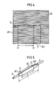
- FIG. 4 now shows the universal adaptability of the cable sleeve insert KE according to the invention.
- a large area GF has to be created from the two composite layers DF and WF that are already adhering together, from or from which the cutting area ZF that is just required is cut or cut.
- the large area GF to be provided is only determined by the manufacturing conditions, that is to say by the possible dimensions of the manufacturing machines.
- This large area GF which is ready to be built, is then stored either as a flat part or in a rolled-up form until the appropriate cut is made if necessary. This eliminates the production and warehousing of different types.
- the length of the middle part for the cable sleeve insert KE can also be freely determined by appropriate choice of the distance A of the transverse beads S1 and S2, with the additional possibility of making the adjustment areas AB1 and AB2 unequal in accordance with the existing conditions to choose in length. In this way, an optimal adaptation to different diameter transitions on both sides is made possible.
- FIG. 5 shows schematically a cable sleeve insert KE produced in accordance with the invention, which is wound up, for example, over a cable splice with the inserted cables K and which is pressed along the inserted beads S1 and S2 by pressing the two outer ends of the cutting surface ZF onto the two diameters of the two cables K is angled and thereby adapted.
- the two adaptation areas AB1 and AB2 are not of the same length.
- the cable gland insert KE provides the desired support over the entire area of the cable sleeve.
Landscapes
- Insulated Conductors (AREA)
- Insulating Bodies (AREA)
- Cable Accessories (AREA)
- Processing Of Terminals (AREA)
- Ropes Or Cables (AREA)
- Details Of Indoor Wiring (AREA)
- Stereo-Broadcasting Methods (AREA)
Abstract
Bei der Erfindung handelt es sich um eine wickelbare Kabelmuffeneinlage (KE) aus einer glatten und einer gewellten, jeweils aus mehreren Materialschichten bestehenden Verbundschicht (DF, WF). Die erforderliche Größe der Kabelmuffeneinlage (KE) wird durch Ausschneiden aus einer Großfläche (GF) und durch Einbringen von quer verlaufenden Sicken (S) in die Wellfolie (WF) hergestellt. 
Description
Die Erfindung betrifft eine wickelbare Kabelmuffeneinlage aus einer glatten und einer gewellten, jeweils aus mehreren Materialschichten bestehende Verbundschicht, wobei diese Verbundschichten übereinander liegend angeordnet sind.The invention relates to a windable cable sleeve insert made of a smooth and a corrugated composite layer, each consisting of several material layers, these composite layers being arranged one above the other.
Aus der europäischen Patentanmeldung EP 0 120 475 ist eine wickelbare Kabelmuffeneinlage für eine schrumpfbare Kabelmuffe bekannt, bei der zwei übereinander liegende Verbundschichten angeordnet sind. Eine dieser Verbundschichten besitzt gewellte Form und überdeckt den gesamten abzudeckenden Bereich, während die zweite Verbundschicht eine glatte Form aufweist und nur im Mittelbereich auf der ersten Verbundschicht zwischen den beiden anpaßbaren Randbereichen der Kabelmuffeneinlage aufgebracht ist. Diese im Mittelbereich aufgebrachte Verbundschicht erhöht die Festigkeit und den Wärmeschutz, während die Randbereiche mit der bloßliegenden Wellung der Anpassung zwischen den Durchmesserunterschieden dient. Dies bedeutet, daß für jeden Muffentyp eine spezielle Kabelmuffeneinlage vorrätig sein muß, die bezüglich Durchmesser und Länge festgelegt werden muß.From the European patent application EP 0 120 475 a windable cable sleeve insert for a shrinkable cable sleeve is known, in which two superimposed composite layers are arranged. One of these composite layers has a corrugated shape and covers the entire area to be covered, while the second composite layer has a smooth shape and is only applied in the middle area on the first composite layer between the two adjustable edge regions of the cable sleeve insert. This composite layer applied in the middle area increases the strength and the heat protection, while the edge areas with the exposed corrugation serve to adapt between the differences in diameter. This means that a special cable sleeve insert must be available for each type of sleeve, which must be defined in terms of diameter and length.
Für vorliegende Erfindung besteht nun die Aufgabe, eine Kabelmuffeneinlage zu schaffen, die in universeller Weise für alle vorkommenden Kabelmuffen verwendbar ist, wobei die vorgegebenen Bedingungen ebenfalls in glei cher Weise erfüllt werden müssen. Die gestellte Aufgabe wird nun mit Hilfe einer wickelbaren Kabelmuffeneinlage der eingangs erläuterten Art dadurch gelöst, daß die beiden zusammenhaftenden aus einer beliebig groß hergestellten Fläche herausgeschnittenen Verbundschichten, vorzugsweise die außenliegende glatte Deckfolie und die innen liegende Wellfolie, sich über den gesamten Kabelmuffenbereich erstreckend angeordnet sind und daß die Wellfolie an beliebiger Stelle quer zur Wellung mit durchgehenden Sicken versehbar ist und daß die beiden Verbundschichten entlang der eingebrachten Sicken zur Anpassung von Durchmesserunterschieden zwischen der gewickelten Kabelmuffeneinlage und den in die Kabelmuffe eingeführten Kabeln abknickbar sind.For the present invention, there is now the task of creating a cable gland insert which can be used in a universal manner for all occurring cable glands, the given conditions also being the same sure way. The task is now solved with the help of a windable cable sleeve insert of the type described in the introduction in that the two adhesive composite layers cut out from a surface of any size, preferably the outer smooth cover film and the inner corrugated film, are arranged to extend over the entire cable sleeve area and that the corrugated film can be provided with continuous beads at any point transverse to the corrugation and that the two composite layers along the inserted beads can be bent to adjust diameter differences between the wound cable sleeve insert and the cables inserted into the cable sleeve.
Weiterhin ist Aufgabe der Erfindung, ein Verfahren zur Herstellung einer solchen Kabelmuffeneinlage zu schaffen. Die Lösung dieser Aufgabe ergibt sich nach den im Patentanspruch 14 beschriebenen Merkmalen.Another object of the invention is to provide a method for producing such a cable sleeve insert. This object is achieved according to the features described in claim 14.
Die Vorteile der Kabelmuffeneinlage gegenüber dem bisherigen Stand der Technik bestehen nun in erster Linie darin, daß lediglich eine einzige Großfläche aus den für die Erfordernisse ausreichenden Verbundfolien herzustellen ist. Diese Großfläche kann in Flächenstücken oder in aufgerollter Form bereitgestellt werden, wobei lediglich die Breite der Großfläche durch die mögliche Fertigungsbreite vorgegeben ist. Dies bedeutet, daß bei Bedarf die gerade erforderliche Größe aus der vorhandenen Großfläche auszuschneiden ist und zwar mit den gerade notwendigen Abmessungen. Nachdem dieses Flächenstück ausgeschnitten ist, können außerdem frei und den Bedürfnissen genau angepaßt die Knicklinien für die beiden seitlichen Anpassungsbereiche bestimmt werden. Auch hier lassen sich die Abmessungen frei wählen, so daß zum Beispiel auch ungleiche Anpassungsstücke möglich sind, wenn beispielsweise Kabel mit ungleichen Durchmessern eingeführt werden. Aus diesen Beispielen heraus läßt sich erkennen, daß diese Kabelmuffeneinlage gemäß der Erfindung in univeseller Weise für alle möglichen Einsatzfälle optimal angepaßt werden kann.The advantages of the cable sleeve insert compared to the prior art now consist primarily in the fact that only a single large area can be produced from the composite films sufficient for the requirements. This large area can be provided in pieces or in rolled up form, only the width of the large area being predetermined by the possible manufacturing width. This means that, if necessary, the size just required must be cut out of the existing large area and with the dimensions just required. After this area piece has been cut out, the crease lines for the two lateral adjustment areas can also be freely and precisely adapted to the needs. Here, too, the dimensions can be chosen freely that, for example, unequal adapters are possible if, for example, cables with unequal diameters are introduced. From these examples it can be seen that this cable sleeve insert according to the invention can be optimally adapted in a universal manner for all possible applications.
Die Erfindung wird nun anhand von fünf Figuren näher erläutert.
- Figur 1 zeigt ein bereits zugeschnittenes Flächenstück in Draufsicht und
- Figur 2 zeigt das Flächenstück nach Figur 1 in Seitenansicht.
- Figur 3 zeigt einen Ausschnittsbereich des Flächenstükkes im Sickenbereich.
- Figur 4 zeigt eine Übersicht über den Zuschnittvorgang.
- Figur 5 zeigt eine aufgewickelte Kabelmuffeneinlage gemäß der Erfindung.
- Figure 1 shows an already cut surface in plan view and
- Figure 2 shows the surface of Figure 1 in side view.
- FIG. 3 shows a cut-out area of the surface piece in the bead area.
- Figure 4 shows an overview of the cutting process.
- Figure 5 shows a wound cable sleeve insert according to the invention.
In der Figur 1 sind in Draufsicht auf die aus einer Verbundschicht bestehenden Wellfolie WF die bestimmenden Zusammenhänge der Kabelmuffeneinlage KE erkennbar. Diese Wellfolie WF ist auf der darunter liegenden, hier nicht sichtbaren Deckfolie fest aufgebracht, wobei die hier gezeigten Abmessungen bereits einer kompletten Kabelmuffeneinlage KE entsprechen sollen. Die Wellung verläuft dabei wie bei allen Kabelmuffeneinlagen KE der Erfindung in Achsrichtung des später zu umwickelnden Gegenstandes, zum Beispiel der Kabel, und wird vorzugsweise beim Umwickeln nach einwärts gerich tet, so daß nach außen die glatte Deckfolie DF sichtbar wird. Beim Aufschrumpfen der schrumpfbaren Umhüllung ergibt sich somit eine glatte Oberfläche. Da der zu umhüllende Gegenstand meist einen anderen Durchmesser aufweist als die eingeführten Gegenstände, muß zwischen diesen unterschiedlichen Durchmessern eine Anpassung erfolgen, die durch Zusammenpressen der beiden äußeren Anpassungsbereiche erfolgt. Dieses Zusammenpressen wird erleichtert durch eine definierte Bruchkante entlang von Sicken S, die in die Wellung W der Wellfolie WF eingebracht werden. Dies erfolgt mit einem beliebigen Falzwerkzeug, das unter Umständen erwärmt wird, so daß die Kunststoffschichten in der Verbundschicht leichter verformbar werden. Diese Sicken S können an beliebiger Stelle eingebracht werden, so daß sich die Längen der Anpassungbereiche AB dadurch beliebig bestimmen und anpassen lassen.In Figure 1, the determining relationships of the cable sleeve insert KE can be seen in a plan view of the corrugated film WF consisting of a composite layer. This corrugated foil WF is firmly attached to the underlying cover foil, which is not visible here, the dimensions shown here already being intended to correspond to a complete cable sleeve insert KE. The corrugation extends, as with all cable sleeve inserts KE of the invention, in the axial direction of the object to be wrapped later, for example the cable, and is preferably directed inward when wrapping tet, so that the smooth cover film DF is visible to the outside. When the shrinkable covering is shrunk on, a smooth surface results. Since the object to be encased usually has a different diameter than the objects introduced, an adaptation must take place between these different diameters, which is carried out by pressing the two outer adaptation regions together. This pressing together is facilitated by a defined breaking edge along beads S which are introduced into the corrugation W of the corrugated film WF. This is done with any folding tool that may be heated so that the plastic layers in the composite layer are easier to deform. These beads S can be introduced at any point, so that the lengths of the adaptation areas AB can be determined and adapted as desired.
Die Figur 2 zeigt eine Queransicht auf die zugeschnittene Kabelmuffeneinlage KE, wodurch der Aufbau aus den beiden Verbundschichten, der Deckfolie DF und der Wellfolie WF deutlich wird. Die gegenseitige Haftung erfolgt zweckmäßigerweise durch Haftfolien der beiden Verbundschichten, die sich gegenüber liegen und entlang der gemeinsamen Berührungslinien BL miteinander verklebt oder verschmolzen sind.FIG. 2 shows a transverse view of the cut cable sleeve insert KE, whereby the structure of the two composite layers, the cover film DF and the corrugated film WF becomes clear. The mutual adhesion expediently takes place by means of adhesive films of the two composite layers, which lie opposite one another and are glued or fused together along the common contact lines BL.
Die Figur 3 zeigt die in Figur 1 angedeutete Ansicht im Bereich einer quer verlaufenden Sicke S. Es wird deutlich, daß die auf die glatte Deckfolie DF aufgebrachte Wellfolie WF eingedellt ist, so daß hier in Richtung dieser Sicke S die Wellung W geschwächt bzw. unterbrochen ist. Auf diese Weise läßt sich entlang dieser Sicke S die Kabelmuffeneinlage leicht abknicken und dadurch entsprechend anpassen. Weiter hin geht aus dieser Figur 3 hervor, daß die als Deckfolie DF ausgeführte Verbundfolie zum Beispiel aus drei Einzelschichten, einer Haftschicht HS, einer Permeationsschutzschicht PS und einer Wärmeschutzschicht WS, besteht. Dies gilt auch entsprechend für die Wellfolie WF, wobei die Anzahl und die Stärke der Einzelschichten unterschiedlich sein kann. Als Haftschicht HS wird ein schmelzbarer Kunststoff, vorzugsweise Polyäthylen, verwendet, wobei die Schichtstärke vorzugsweise zwischen 15 bis 40 µm beträgt. Die Permeationsschutzschicht PS besteht vorzugsweise aus Metall, beispielsweise aus Aluminium, und ist für die Deckfolie DF zwischen vorzugsweise 15 bis 40 µm und für die Wellfolie WF 30 bis 60 µm stark. Die darüber liegende Wärmeschutzschicht WS besteht wiederum aus einem Kunststoff, vorzugsweise aus Polyester (PETP) und ist in einer Stärke von 10 bis 80 µm aufgebracht. Ein typisches Ausführungsbeispiel für eine Kabelmuffeneinlage weist folgende Verbundschichten auf:
Deckfolie: Haftschicht HS aus einer 25 µm starken Schicht aus Polyethylen
Permeationsschutzschicht PS aus einer 20 µm starken Schicht aus Aluminium
Wärmeschutzschicht WS aus einer 12 µm starken Schicht aus Polyester (PETP)
Wellfolie: Haftschicht HS aus einer 25 µm starken Schicht aus Polyethylen
Permeationsschutzschicht PS aus einer 35 µm starken Schicht aus Aluminium
Wärmeschutzschicht WS aus einer 75 µm starken Schicht aus Polyester (PETP)FIG. 3 shows the view indicated in FIG. 1 in the area of a transverse bead S. It is clear that the corrugated sheet WF applied to the smooth cover sheet DF is dented, so that the corrugation W is weakened or interrupted in the direction of this bead S. is. In this way, the cable sleeve insert can be easily bent along this bead S and thus adjusted accordingly. Continue 3 shows that the composite film designed as a cover film DF consists, for example, of three individual layers, an adhesive layer HS, a permeation protection layer PS and a heat protection layer WS. This also applies accordingly to the corrugated film WF, the number and the thickness of the individual layers being different. A fusible plastic, preferably polyethylene, is used as the adhesive layer HS, the layer thickness preferably being between 15 and 40 μm. The permeation protection layer PS is preferably made of metal, for example aluminum, and is between 15 to 40 μm thick for the cover film DF and 30 to 60 μm thick for the corrugated film WF. The overlying thermal protection layer WS in turn consists of a plastic, preferably polyester (PETP) and is applied in a thickness of 10 to 80 μm. A typical exemplary embodiment for a cable sleeve insert has the following composite layers:
Cover film: adhesive layer HS made of a 25 µm thick layer of polyethylene
Permeation protection layer PS made of a 20 µm thick layer of aluminum
Thermal protection layer WS made of a 12 µm thick layer of polyester (PETP)
Corrugated film: adhesive layer HS made of a 25 µm thick layer of polyethylene
Permeation protection layer PS made of a 35 µm thick layer of aluminum
Thermal protection layer WS made of a 75 µm thick layer of polyester (PETP)
Die Figur 4 zeigt nun die universelle Anpassungsmöglichkeit der Kabelmuffeneinlage KE gemäß der Erfindung. So ist lediglich eine Großfläche GF aus den beiden bereits zusammenhaftenden Verbundschichten DF und WF zu erstellen, aus der bzw. von der die gerade erforderliche Zuschnittfläche ZF aus- bzw. abgeschnitten wird. Die bereitzustellende Großfläche GF ist nur bestimmt von den Herstellungsgegebenheiten, das heißt von den möglichen Abmessungen der Herstellungsmaschinen. Diese hergestellte, im Aufbau fertige Großfläche GF wird dann entweder als Flächenteil oder in aufgerollter Form gelagert, bis bei Bedarf der entsprechende Zuschnitt erfolgt. Damit entfällt die Fertigung und Lagerhaltung von verschiedenen Typen. Nach dem Zuschnitt entlang der Schnittlinie SL kann außerdem noch die Länge des Mittelteils für die Kabelmuffeneinlage KE durch entsprechende Wahl des Abstandes A der querverlaufenden Sicken S1 und S2 frei bestimmt werden, wobei zusätzlich die Möglichkeit besteht, die Anpassungsbereiche AB1 und AB2 entsprechend den vorliegenden Verhältnissen ungleich in der Länge zu wählen. Auf diese Weise ist auch eine optimale Anpassung an verschiedene Durchmesserübergänge an beiden Seiten ermöglicht.FIG. 4 now shows the universal adaptability of the cable sleeve insert KE according to the invention. Thus, only a large area GF has to be created from the two composite layers DF and WF that are already adhering together, from or from which the cutting area ZF that is just required is cut or cut. The large area GF to be provided is only determined by the manufacturing conditions, that is to say by the possible dimensions of the manufacturing machines. This large area GF, which is ready to be built, is then stored either as a flat part or in a rolled-up form until the appropriate cut is made if necessary. This eliminates the production and warehousing of different types. After cutting along the cutting line SL, the length of the middle part for the cable sleeve insert KE can also be freely determined by appropriate choice of the distance A of the transverse beads S1 and S2, with the additional possibility of making the adjustment areas AB1 and AB2 unequal in accordance with the existing conditions to choose in length. In this way, an optimal adaptation to different diameter transitions on both sides is made possible.
Die Figur 5 zeigt nun schließlich schematisch eine auf erfindungsgemäße Weise hergestellte Kabelmuffeneinlage KE, die zum Beispiel über einem Kabelspleiß mit den eingeführten Kabeln K aufgewickelt ist und die entlang der eingebrachten Sicken S1 und S2 durch Zusammenpressen der beiden äußeren Enden der Zuschnittsfläche ZF auf die beiden Duchmesser der beiden Kabel K abgewinkelt und dadurch angepaßt ist. Hierbei ist skizzenhaft angedeutet, daß die beiden Anpassungsbereiche AB1 und AB2 ungleich lang sind. Über diese an gepaßte Kabelmuffeneinlage KE kann nun in einfacher Weise eine schrumpfbare Umhüllung dichtend aufgebracht werden, wobei die Kabelmuffeneinlage KE die gewünschte Stützung über den gesamten Bereich der Kabelmuffe hin ergibt.Finally, FIG. 5 shows schematically a cable sleeve insert KE produced in accordance with the invention, which is wound up, for example, over a cable splice with the inserted cables K and which is pressed along the inserted beads S1 and S2 by pressing the two outer ends of the cutting surface ZF onto the two diameters of the two cables K is angled and thereby adapted. Here it is indicated sketchily that the two adaptation areas AB1 and AB2 are not of the same length. About this one fit cable gland insert KE can now be easily applied a shrinkable sheath sealing, the cable gland insert KE provides the desired support over the entire area of the cable sleeve.
Claims (15)
Priority Applications (1)
| Application Number | Priority Date | Filing Date | Title |
|---|---|---|---|
| AT87108723T ATE56842T1 (en) | 1986-06-19 | 1987-06-16 | COILABLE CABLE SLEEVE AND MANUFACTURE OF THE SAME. |
Applications Claiming Priority (2)
| Application Number | Priority Date | Filing Date | Title |
|---|---|---|---|
| DE3620522 | 1986-06-19 | ||
| DE3620522 | 1986-06-19 |
Publications (3)
| Publication Number | Publication Date |
|---|---|
| EP0249972A2 true EP0249972A2 (en) | 1987-12-23 |
| EP0249972A3 EP0249972A3 (en) | 1988-07-20 |
| EP0249972B1 EP0249972B1 (en) | 1990-09-19 |
Family
ID=6303247
Family Applications (1)
| Application Number | Title | Priority Date | Filing Date |
|---|---|---|---|
| EP87108723A Expired - Lifetime EP0249972B1 (en) | 1986-06-19 | 1987-06-16 | Wrap around cable sleeve insert and manufacturing of the same |
Country Status (9)
| Country | Link |
|---|---|
| US (1) | US4792472A (en) |
| EP (1) | EP0249972B1 (en) |
| AT (1) | ATE56842T1 (en) |
| AU (1) | AU600492B2 (en) |
| DE (1) | DE3765021D1 (en) |
| FI (1) | FI84119C (en) |
| HU (1) | HU204147B (en) |
| IN (1) | IN164983B (en) |
| TR (1) | TR23559A (en) |
Cited By (4)
| Publication number | Priority date | Publication date | Assignee | Title |
|---|---|---|---|---|
| EP0373476A3 (en) * | 1988-12-16 | 1991-05-02 | RXS Schrumpftechnik-Garnituren GmbH | Longitudinally divided cable sleeve comprising a flexible envelope, and semi-finished product for manufacturing such a cable sleeve |
| EP0373477A3 (en) * | 1988-12-16 | 1991-05-02 | RXS Schrumpftechnik-Garnituren GmbH | Light construction longitudinally divided overhead sleeve |
| WO2000054384A1 (en) * | 1999-03-10 | 2000-09-14 | Rxs Gesellschaft Für Vermögensverwaltung Mbh | Cable joint comprised of a shrinkable sheathing and of a protective insert |
| WO2008077434A1 (en) * | 2006-12-27 | 2008-07-03 | Raychem Electronics (Shanghai) Ltd. | Sleeve adapted to be shortened in an expanded state |
Families Citing this family (3)
| Publication number | Priority date | Publication date | Assignee | Title |
|---|---|---|---|---|
| ES2064501T3 (en) * | 1989-03-03 | 1995-02-01 | Rxs Schrumpftech Garnituren | HOT CONTRACTION WRAP. |
| KR930702809A (en) * | 1990-10-09 | 1993-09-09 | 허버트지. 버카드 | Environmental Antioxidant Wraps for Airtight Enclosures |
| US11685322B2 (en) * | 2020-09-04 | 2023-06-27 | Caterpillar Inc. | Wiring harness assembly having 3-dimensional sleeve guide, and method of making same |
Family Cites Families (11)
| Publication number | Priority date | Publication date | Assignee | Title |
|---|---|---|---|---|
| DE539612C (en) * | 1931-11-28 | Robert Jakobi | packing material | |
| US1189140A (en) * | 1915-08-26 | 1916-06-27 | Sidney David Lane | Corrugated or like packing material. |
| FR522546A (en) * | 1920-07-20 | 1921-08-01 | Gabriel Sutre | Corrugated paper tubes for various packaging |
| US2624989A (en) * | 1949-08-03 | 1953-01-13 | Hankins Container Company | Method of packaging elongated articles |
| US2642372A (en) * | 1950-02-02 | 1953-06-16 | Chittick Charles Yardley | Flexible corrugated sheet material and method of fabricating same |
| US3879249A (en) * | 1972-02-22 | 1975-04-22 | Minnesota Mining & Mfg | Cable enclosure |
| US4258092A (en) * | 1978-08-31 | 1981-03-24 | Morgan Adhesives Co. | Laminate with removable scored paper backing |
| DE7930401U1 (en) * | 1979-09-11 | 1980-03-13 | N.V. Raychem S.A., Kessel-Lo (Belgien) | Cable sleeve insert |
| US4565316A (en) * | 1983-03-04 | 1986-01-21 | Willamette Industries, Inc. | Two-piece asparagus carton |
| DE3311011A1 (en) * | 1983-03-25 | 1984-09-27 | Siemens AG, 1000 Berlin und 8000 München | CABLE SOCKET INSERT FOR A SHRINKABLE CABLE SLEEVE |
| DE3441311A1 (en) * | 1984-11-12 | 1986-05-15 | Siemens AG, 1000 Berlin und 8000 München | SPLICE PROTECTOR INSERT FOR CABLE SLEEVES MADE OF SHRINKABLE MATERIAL |
-
1987
- 1987-04-16 IN IN300/CAL/87A patent/IN164983B/en unknown
- 1987-06-16 US US07/062,679 patent/US4792472A/en not_active Expired - Fee Related
- 1987-06-16 EP EP87108723A patent/EP0249972B1/en not_active Expired - Lifetime
- 1987-06-16 AT AT87108723T patent/ATE56842T1/en not_active IP Right Cessation
- 1987-06-16 DE DE8787108723T patent/DE3765021D1/en not_active Expired - Fee Related
- 1987-06-18 TR TR416/87A patent/TR23559A/en unknown
- 1987-06-18 AU AU74482/87A patent/AU600492B2/en not_active Ceased
- 1987-06-18 FI FI872745A patent/FI84119C/en not_active IP Right Cessation
- 1987-06-18 HU HU872784A patent/HU204147B/en not_active IP Right Cessation
Cited By (6)
| Publication number | Priority date | Publication date | Assignee | Title |
|---|---|---|---|---|
| EP0373476A3 (en) * | 1988-12-16 | 1991-05-02 | RXS Schrumpftechnik-Garnituren GmbH | Longitudinally divided cable sleeve comprising a flexible envelope, and semi-finished product for manufacturing such a cable sleeve |
| EP0373477A3 (en) * | 1988-12-16 | 1991-05-02 | RXS Schrumpftechnik-Garnituren GmbH | Light construction longitudinally divided overhead sleeve |
| WO2000054384A1 (en) * | 1999-03-10 | 2000-09-14 | Rxs Gesellschaft Für Vermögensverwaltung Mbh | Cable joint comprised of a shrinkable sheathing and of a protective insert |
| WO2008077434A1 (en) * | 2006-12-27 | 2008-07-03 | Raychem Electronics (Shanghai) Ltd. | Sleeve adapted to be shortened in an expanded state |
| GB2458092A (en) * | 2006-12-27 | 2009-09-09 | Tyco Electronics Raychem Gmbh | Sleeve adapted to be shortened in an expanded state |
| GB2458092B (en) * | 2006-12-27 | 2011-08-17 | Raychem Electronics | Shrink sleeve |
Also Published As
| Publication number | Publication date |
|---|---|
| IN164983B (en) | 1989-07-22 |
| FI872745L (en) | 1987-12-20 |
| HU204147B (en) | 1991-11-28 |
| ATE56842T1 (en) | 1990-10-15 |
| HUT44681A (en) | 1988-03-28 |
| EP0249972A3 (en) | 1988-07-20 |
| DE3765021D1 (en) | 1990-10-25 |
| EP0249972B1 (en) | 1990-09-19 |
| AU600492B2 (en) | 1990-08-16 |
| FI84119B (en) | 1991-06-28 |
| FI84119C (en) | 1991-10-10 |
| AU7448287A (en) | 1987-12-24 |
| FI872745A0 (en) | 1987-06-18 |
| US4792472A (en) | 1988-12-20 |
| TR23559A (en) | 1990-03-26 |
Similar Documents
| Publication | Publication Date | Title |
|---|---|---|
| EP0188777B1 (en) | Cable sleeve provided with a cross-sectionally cross-shaped device for supporting cable ends entering cable sleeves | |
| DE2625100C3 (en) | Use of a conical shell made of heat-shrinkable plastic for coating a glass container | |
| DE69621448T2 (en) | HEAT-RESETTABLE OBJECT AND METHOD FOR SEALING CABLE CONNECTIONS | |
| DE2731578C3 (en) | Cable sleeve with a metallic support jacket and sleeve heads adjoining these on both sides, as well as a plastic shrink tubing that connects these parts to one another | |
| DE3789600T2 (en) | Cable connections with sealing. | |
| EP0249972B1 (en) | Wrap around cable sleeve insert and manufacturing of the same | |
| EP0120475B1 (en) | Cable sleeve insert for a shrinkable cable sleeve | |
| DE3439711A1 (en) | INSERT FOR A CABLE SLEEVE AND A METHOD FOR PRODUCING THE SAME IN THE CABLE SLEEVE | |
| EP1128176A2 (en) | Strand of mutually connected metallic balancing weights | |
| EP0226940B1 (en) | Cable sleeve capable of contraction | |
| DE2542508A1 (en) | Sleeve and coupling for metal clad cables - simplifies fitting and provides protection for multiple cable joints | |
| DE3026123C2 (en) | Cable sleeve with insert that can be wrapped around the splice | |
| DE4002828C2 (en) | ||
| EP0468204B1 (en) | Metal sheet or metal strips | |
| EP0765020A2 (en) | Device for sealingly enclosing a substrate | |
| EP0525519B1 (en) | Heat-shrinkable composite sheet | |
| DE3501243C2 (en) | ||
| DE19742078A1 (en) | Cable sleeve with insert surrounding splice | |
| DE1965224A1 (en) | Method and device for producing pairs or vials of telephone cables in one operation | |
| DE3211714C2 (en) | ||
| EP0423551B1 (en) | Heat-shrinkable covering with reinforcing insert | |
| EP0940900A1 (en) | Cable sleeve with an insert enclosing a splice | |
| EP0125596A1 (en) | Insulating strip cover | |
| DE3232352A1 (en) | Protective sheath for annular-core windings | |
| DE69214511T2 (en) | Method and device for inserting an edge strip between two strip-shaped film webs coated on both sides |
Legal Events
| Date | Code | Title | Description |
|---|---|---|---|
| PUAI | Public reference made under article 153(3) epc to a published international application that has entered the european phase |
Free format text: ORIGINAL CODE: 0009012 |
|
| AK | Designated contracting states |
Kind code of ref document: A2 Designated state(s): AT BE CH DE FR GB IT LI NL SE |
|
| PUAL | Search report despatched |
Free format text: ORIGINAL CODE: 0009013 |
|
| AK | Designated contracting states |
Kind code of ref document: A3 Designated state(s): AT BE CH DE FR GB IT LI NL SE |
|
| 17P | Request for examination filed |
Effective date: 19881010 |
|
| 17Q | First examination report despatched |
Effective date: 19890512 |
|
| GRAA | (expected) grant |
Free format text: ORIGINAL CODE: 0009210 |
|
| AK | Designated contracting states |
Kind code of ref document: B1 Designated state(s): AT BE CH DE FR GB IT LI NL SE |
|
| REF | Corresponds to: |
Ref document number: 56842 Country of ref document: AT Date of ref document: 19901015 Kind code of ref document: T |
|
| REF | Corresponds to: |
Ref document number: 3765021 Country of ref document: DE Date of ref document: 19901025 |
|
| ET | Fr: translation filed | ||
| ITF | It: translation for a ep patent filed | ||
| GBT | Gb: translation of ep patent filed (gb section 77(6)(a)/1977) | ||
| ITTA | It: last paid annual fee | ||
| PLBE | No opposition filed within time limit |
Free format text: ORIGINAL CODE: 0009261 |
|
| STAA | Information on the status of an ep patent application or granted ep patent |
Free format text: STATUS: NO OPPOSITION FILED WITHIN TIME LIMIT |
|
| 26N | No opposition filed | ||
| K2C2 | Correction of patent specification (partial reprint) published |
Effective date: 19900919 |
|
| PGFP | Annual fee paid to national office [announced via postgrant information from national office to epo] |
Ref country code: GB Payment date: 19930510 Year of fee payment: 7 |
|
| PGFP | Annual fee paid to national office [announced via postgrant information from national office to epo] |
Ref country code: AT Payment date: 19930519 Year of fee payment: 7 |
|
| PGFP | Annual fee paid to national office [announced via postgrant information from national office to epo] |
Ref country code: BE Payment date: 19930608 Year of fee payment: 7 |
|
| PGFP | Annual fee paid to national office [announced via postgrant information from national office to epo] |
Ref country code: FR Payment date: 19930618 Year of fee payment: 7 |
|
| PGFP | Annual fee paid to national office [announced via postgrant information from national office to epo] |
Ref country code: SE Payment date: 19930622 Year of fee payment: 7 |
|
| PGFP | Annual fee paid to national office [announced via postgrant information from national office to epo] |
Ref country code: NL Payment date: 19930630 Year of fee payment: 7 |
|
| PGFP | Annual fee paid to national office [announced via postgrant information from national office to epo] |
Ref country code: DE Payment date: 19930819 Year of fee payment: 7 |
|
| PGFP | Annual fee paid to national office [announced via postgrant information from national office to epo] |
Ref country code: CH Payment date: 19930916 Year of fee payment: 7 |
|
| PG25 | Lapsed in a contracting state [announced via postgrant information from national office to epo] |
Ref country code: GB Effective date: 19940616 Ref country code: AT Effective date: 19940616 |
|
| PG25 | Lapsed in a contracting state [announced via postgrant information from national office to epo] |
Ref country code: SE Effective date: 19940617 |
|
| PG25 | Lapsed in a contracting state [announced via postgrant information from national office to epo] |
Ref country code: LI Effective date: 19940630 Ref country code: CH Effective date: 19940630 Ref country code: BE Effective date: 19940630 |
|
| BERE | Be: lapsed |
Owner name: RXS SCHRUMPFTECHNIK-GARNITUREN G.M.B.H. Effective date: 19940630 |
|
| PG25 | Lapsed in a contracting state [announced via postgrant information from national office to epo] |
Ref country code: NL Effective date: 19950101 |
|
| EUG | Se: european patent has lapsed |
Ref document number: 87108723.5 Effective date: 19950110 |
|
| GBPC | Gb: european patent ceased through non-payment of renewal fee |
Effective date: 19940616 |
|
| NLV4 | Nl: lapsed or anulled due to non-payment of the annual fee | ||
| PG25 | Lapsed in a contracting state [announced via postgrant information from national office to epo] |
Ref country code: FR Effective date: 19950228 |
|
| REG | Reference to a national code |
Ref country code: CH Ref legal event code: PL |
|
| PG25 | Lapsed in a contracting state [announced via postgrant information from national office to epo] |
Ref country code: DE Effective date: 19950301 |
|
| EUG | Se: european patent has lapsed |
Ref document number: 87108723.5 |
|
| REG | Reference to a national code |
Ref country code: FR Ref legal event code: ST |
|
| PG25 | Lapsed in a contracting state [announced via postgrant information from national office to epo] |
Ref country code: IT Free format text: LAPSE BECAUSE OF NON-PAYMENT OF DUE FEES;WARNING: LAPSES OF ITALIAN PATENTS WITH EFFECTIVE DATE BEFORE 2007 MAY HAVE OCCURRED AT ANY TIME BEFORE 2007. THE CORRECT EFFECTIVE DATE MAY BE DIFFERENT FROM THE ONE RECORDED. Effective date: 20050616 |