EP0249900A2 - Dispositif de pompage et de dispersion de matériaux épais comme par exemple le mortier de plâtrage - Google Patents
Dispositif de pompage et de dispersion de matériaux épais comme par exemple le mortier de plâtrage Download PDFInfo
- Publication number
- EP0249900A2 EP0249900A2 EP87108482A EP87108482A EP0249900A2 EP 0249900 A2 EP0249900 A2 EP 0249900A2 EP 87108482 A EP87108482 A EP 87108482A EP 87108482 A EP87108482 A EP 87108482A EP 0249900 A2 EP0249900 A2 EP 0249900A2
- Authority
- EP
- European Patent Office
- Prior art keywords
- delivery
- storage container
- cylinders
- cylinder
- gearbox
- Prior art date
- Legal status (The legal status is an assumption and is not a legal conclusion. Google has not performed a legal analysis and makes no representation as to the accuracy of the status listed.)
- Withdrawn
Links
Images

Classifications
-
- E—FIXED CONSTRUCTIONS
- E04—BUILDING
- E04F—FINISHING WORK ON BUILDINGS, e.g. STAIRS, FLOORS
- E04F21/00—Implements for finishing work on buildings
- E04F21/02—Implements for finishing work on buildings for applying plasticised masses to surfaces, e.g. plastering walls
- E04F21/06—Implements for applying plaster, insulating material, or the like
- E04F21/08—Mechanical implements
- E04F21/10—Mechanical implements centrifugally acting
-
- F—MECHANICAL ENGINEERING; LIGHTING; HEATING; WEAPONS; BLASTING
- F04—POSITIVE - DISPLACEMENT MACHINES FOR LIQUIDS; PUMPS FOR LIQUIDS OR ELASTIC FLUIDS
- F04B—POSITIVE-DISPLACEMENT MACHINES FOR LIQUIDS; PUMPS
- F04B15/00—Pumps adapted to handle specific fluids, e.g. by selection of specific materials for pumps or pump parts
- F04B15/02—Pumps adapted to handle specific fluids, e.g. by selection of specific materials for pumps or pump parts the fluids being viscous or non-homogeneous
Definitions
- the invention relates to a device for conveying and spraying viscous masses, such as mortar for plastering purposes, with a storage container, a conveying line and two mutually parallel, spaced apart delivery cylinders with delivery pistons.
- the invention has set itself the task of creating a simplified and robust construction that allows a compact design, so as to keep the spatial dimensions of the device as small as possible, mindful of the fact that such devices are subject to frequent changes of location and that such devices must be used in unfinished buildings, in which they can often be transported from one floor to the other without mechanical aids and lifting means.
- the invention now proposes that the delivery pistons are each connected to a crankshaft via a piston rod and a push rod, so that the crankshafts, which are aligned with one another, are arranged on diametrical sides of a gearbox, the width of which, measured in the axial direction of the crankshafts, corresponds approximately to the mutual distance between the delivery cylinders and a drive motor is flanged to the gearbox and delivery cylinder, gear box and drive motor are arranged on the side of the storage container and motor and gear box are located on the side between the delivery cylinders.
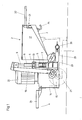
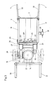
- a storage container 2 On a chassis 1 made of profile tubes, a storage container 2 is mounted with an inclined bottom 3 and a vertical end wall 4, which encloses an acute angle with the above-mentioned bottom, so that the storage container 2 is a side view (Fig. 1 and Fig. 2) Wedge shape shows.
- a side view Fig. 1 and Fig. 2 Wedge shape shows.
- two delivery cylinders 5, 6 with vertical axes are arranged upright, which are spaced apart from one another, the imaginary plane connecting the central axes of the delivery cylinders 5 and 6 lying parallel to the end wall 4 of the storage container 2.
- Each of these delivery cylinders 5, 6 has an inlet and outlet valve, not shown here, these valves are expediently designed as ball valves.
- feed pistons 7 are slidably mounted, each of which is connected to a piston rod 8, 9.
- These piston rods run through guides 10, 11, which are fastened to the upper edge of the delivery cylinders 5 and 6, but are at a distance from this edge, so that openings 12 and 13 are recessed here, through which openings on the side of the piston rods 8, 9 lying space of the delivery cylinder 5, 6 is connected to the outside.
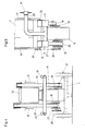
- a gear box 14 with a gear is mounted on the chassis 1, which has shaft outputs on two diametrical sides, which are connected to crankshafts 15 and 16.
- the mentioned diametrically opposite sides of the gearbox 14, which have the shaft outputs, lie essentially parallel to the two side walls 17 and 18 of the storage container 2, which enclose the bottom 3 inclined towards the front side between them.
- Push rods 19 and 20 are connected to the crankshafts 15 and 16 and are articulated to the free ends of the vertical piston rods 8 and 9, respectively.
- the chassis 1 is supported by a wheel axle 21 in the area of the gearbox 14.
- An electric drive motor 22 with a vertical axis is flanged to the top of the gearbox 14 and drives the gearbox mounted in the gearbox 14 and thus the crankshafts 15 and 16.
- each of these suction channels leads to one of the immediately adjacent delivery cylinders 5 and 6 above the inlet mouths of these suction channels 23 and 24 is in the reservoir 2, a screw conveyor 25, the axis of which runs parallel to the end wall 4 of the reservoir 2 and this screw conveyor 25 has two axially adjacent screws 25 ⁇ and 25 ⁇ with opposite slopes.
- the shaft or axis of the screw conveyor 25 is guided on one side of the storage container 2 through its side wall 18 and here carries a pinion 26 which is connected via a chain 27 to a chain wheel 28 which in turn is fastened to the one crankshaft 16.
- the pressure sides of the two delivery cylinders 5 and 6 are connected to one another via a common line 29, which leads to a hose connection 30, this line 29 and the connection 30 mentioned running below the storage container 2.
- a switch box and control devices are also arranged on the chassis 1, which serve to control and monitor the proper operation, but which are not shown here for the sake of clarity.
- a membrane switch which is located in the control circuit of the drive motor 22, is expediently connected to the pressure line 29, which leads to the hose connection 30.
- a reel can also be rotatably arranged in the storage container 2, the rotary movement of which can also be derived from a crankshaft, as was explained in connection with the screw conveyor 25.
- moistened mortar is poured into the reservoir 2, a delivery hose is connected to the hose connection 30 with a lockable spray nozzle.
- the activated drive motor 22 drives the crankshafts 15 and 16 via the gearbox in the gearbox 14, which in turn move the feed pistons in the feed cylinders 5 and 6 alternately via the push rods 19 and 20.
- the mortar is fed to the suction channels 23 and 24 via the screw conveyor 25 with its two mutually opposite screws 25 ⁇ and 25 ⁇ , compressed via the feed cylinder and the feed piston and pressed into the line 29. If the pressure in line 29 rises above a permissible level, the latter is switched off via the membrane switch mentioned, which is not shown here and which is in the control circuit of motor 22. If the delivery pistons leak, so that mortar can penetrate into the cylinder space above which the delivery piston is located, this mortar can flow out through openings 12 and 13, respectively.
- the chassis 1 is supported in that area by the wheel axle 21, where the greatest weight (drive motor 22 and gear) is arranged is.
- the overall height is low, so that the device can easily be placed under mortar silos.
- the swing-out support bars 32 and 33 allow easy transportation by two workers if the device is to be transported over floors. In the plane, the device can be moved in the manner of a wheelbarrow thanks to the wheel axle 21 and the support bars 32.
- the drive motor 22 and / or the gear can be controllable.
- a hook 34 can also be welded to the underside of the storage container 2, to which an air compressor can be attached, which is used for operating the device.
- the moving parts can be covered by protective hoods, which, however, have not been shown here for the sake of clarity.
- the representation of the bottom view according to fig. 5 the chassis parts have been omitted, also for the sake of clarity of illustration. Since the weight of the gearbox including the gearbox therein is considerably greater than that of the drive motor, the device also has a low center of gravity, which makes it easier to handle.
- the vertically standing delivery cylinders 5 and 6 are expediently supported laterally with respect to the gearbox. The struts used for this are not shown here.
Landscapes
- Engineering & Computer Science (AREA)
- Architecture (AREA)
- Civil Engineering (AREA)
- Structural Engineering (AREA)
- Mechanical Engineering (AREA)
- General Engineering & Computer Science (AREA)
- Reciprocating Pumps (AREA)
- Coating Apparatus (AREA)
- On-Site Construction Work That Accompanies The Preparation And Application Of Concrete (AREA)
Applications Claiming Priority (2)
| Application Number | Priority Date | Filing Date | Title |
|---|---|---|---|
| AT166386 | 1986-06-18 | ||
| AT1663/86 | 1986-06-18 |
Publications (2)
| Publication Number | Publication Date |
|---|---|
| EP0249900A2 true EP0249900A2 (fr) | 1987-12-23 |
| EP0249900A3 EP0249900A3 (fr) | 1989-12-13 |
Family
ID=3518296
Family Applications (1)
| Application Number | Title | Priority Date | Filing Date |
|---|---|---|---|
| EP87108482A Withdrawn EP0249900A3 (fr) | 1986-06-18 | 1987-06-12 | Dispositif de pompage et de dispersion de matériaux épais comme par exemple le mortier de plâtrage |
Country Status (1)
| Country | Link |
|---|---|
| EP (1) | EP0249900A3 (fr) |
Cited By (1)
| Publication number | Priority date | Publication date | Assignee | Title |
|---|---|---|---|---|
| DE102017000866A1 (de) * | 2017-01-31 | 2018-08-16 | Liebherr-Betonpumpen Gmbh | Betonförderpumpe |
Family Cites Families (7)
| Publication number | Priority date | Publication date | Assignee | Title |
|---|---|---|---|---|
| FR702301A (fr) * | 1929-12-18 | 1931-04-04 | Perfectionnements apportés aux pompes pour matières épaisses et notamment aux pompes à vendange | |
| FR759993A (fr) * | 1932-08-18 | 1934-02-14 | Machine pour la manutention pulsatoire des mortiers et en particulier du béton par effet de refoulement | |
| FR762896A (fr) * | 1933-10-25 | 1934-04-19 | Richier Sa | Pompe à béton ou autres matériaux similaires |
| DE1004478B (de) * | 1953-07-20 | 1957-03-14 | Karl Sturm | Mehrzylinderpumpe zum Foerdern von zaehfluessigem beziehungsweise koernigem Gut |
| GB813377A (en) * | 1954-08-06 | 1959-05-13 | Ewen Butcher | Apparatus for moulding concrete curbs, gutters and the like |
| CA929413A (en) * | 1970-09-10 | 1973-07-03 | Mancole Company Limited | Concrete pump |
| US4102613A (en) * | 1977-01-06 | 1978-07-25 | Vukich Martin T | Concrete pumping machine |
-
1987
- 1987-06-12 EP EP87108482A patent/EP0249900A3/fr not_active Withdrawn
Cited By (1)
| Publication number | Priority date | Publication date | Assignee | Title |
|---|---|---|---|---|
| DE102017000866A1 (de) * | 2017-01-31 | 2018-08-16 | Liebherr-Betonpumpen Gmbh | Betonförderpumpe |
Also Published As
| Publication number | Publication date |
|---|---|
| EP0249900A3 (fr) | 1989-12-13 |
Similar Documents
| Publication | Publication Date | Title |
|---|---|---|
| AT408365B (de) | Betonspritzmaschine | |
| AT507976B1 (de) | Streuvorrichtung zum streuen von streugut vor die räder eines fahrzeugs | |
| DE2364830C3 (de) | Vorrichtung zum Entleeren eines Schüttgutbunkers | |
| DE593597C (de) | Fluessigkeitspumpe | |
| DE2929652A1 (de) | Reinigungsgeraet zum nassreinigen von gebaeudewaenden und -boeden, schwimmbecken, automobilen o.dgl. | |
| DE2407657A1 (de) | Vorrichtung zum kontinuierlichen mischen eines baustoffs mit wasser | |
| EP0249900A2 (fr) | Dispositif de pompage et de dispersion de matériaux épais comme par exemple le mortier de plâtrage | |
| EP0874769B1 (fr) | Contenant pour substances fluides et coulantes, notamment pour enduits, mortier etc | |
| DE3301517A1 (de) | Abtoenungsmaschine fuer anstrichfarben | |
| EP0806387A2 (fr) | Dispositif pour appliquer une couche de mortier | |
| DE2315857C3 (fr) | ||
| DE19524048C2 (de) | Pumpe zur Förderung nicht fließfähiger Medien | |
| DE4014462A1 (de) | Vorrichtung zum auflockern von schuettgut | |
| DE102020133030A1 (de) | Dickstofffördervorrichtung mit Rüttelvorrichtung | |
| DE10118071C2 (de) | Exzenter-Schneckenpumpe | |
| DE2833809C2 (de) | Kran mit beweglichem Gegengewicht | |
| DE2056145A1 (de) | Betonspritzmaschine | |
| DE1019964B (de) | Vorrichtung zum Foerdern von in teigigem Zustand befindlichen Stoffen oder Stoffgemischen, insbesondere zum Foerdern von Sumpfkalk aus einer Grube | |
| DE547459C (de) | Stampfmaschine | |
| DE931338C (de) | Bandstrasse mit angebauter Rueckvorrichtung | |
| DE4221191A1 (de) | Aufbringungseinrichtung für Klebemittel | |
| DE1921751C3 (de) | Förderer für staubförmiges Gut | |
| DE2138113A1 (de) | Einrichtung zur verarbeitung moertelaehnlicher massen | |
| DE2948601A1 (de) | Misch- und pumpeinrichtung | |
| CH667036A5 (en) | Mortar or plaster mixing machine - is driven by electric motor and mounted on wheelbarrow |
Legal Events
| Date | Code | Title | Description |
|---|---|---|---|
| PUAI | Public reference made under article 153(3) epc to a published international application that has entered the european phase |
Free format text: ORIGINAL CODE: 0009012 |
|
| AK | Designated contracting states |
Kind code of ref document: A2 Designated state(s): CH DE FR IT LI |
|
| PUAL | Search report despatched |
Free format text: ORIGINAL CODE: 0009013 |
|
| AK | Designated contracting states |
Kind code of ref document: A3 Designated state(s): CH DE FR IT LI |
|
| STAA | Information on the status of an ep patent application or granted ep patent |
Free format text: STATUS: THE APPLICATION IS DEEMED TO BE WITHDRAWN |
|
| 18D | Application deemed to be withdrawn |
Effective date: 19900614 |