EP0249601B1 - Gerippe bestehend aus stabförmigen elementen - Google Patents
Gerippe bestehend aus stabförmigen elementen Download PDFInfo
- Publication number
- EP0249601B1 EP0249601B1 EP86906748A EP86906748A EP0249601B1 EP 0249601 B1 EP0249601 B1 EP 0249601B1 EP 86906748 A EP86906748 A EP 86906748A EP 86906748 A EP86906748 A EP 86906748A EP 0249601 B1 EP0249601 B1 EP 0249601B1
- Authority
- EP
- European Patent Office
- Prior art keywords
- rod
- framework according
- elements
- connecting elements
- shaft
- Prior art date
- Legal status (The legal status is an assumption and is not a legal conclusion. Google has not performed a legal analysis and makes no representation as to the accuracy of the status listed.)
- Expired - Lifetime
Links
- 230000008878 coupling Effects 0.000 claims description 4
- 238000010168 coupling process Methods 0.000 claims description 4
- 238000005859 coupling reaction Methods 0.000 claims description 4
- 239000000463 material Substances 0.000 claims description 4
- 239000011796 hollow space material Substances 0.000 claims 1
- 238000010276 construction Methods 0.000 abstract description 17
- 125000006850 spacer group Chemical group 0.000 description 4
- 238000004519 manufacturing process Methods 0.000 description 3
- 230000000149 penetrating effect Effects 0.000 description 2
- 230000015572 biosynthetic process Effects 0.000 description 1
- 238000001746 injection moulding Methods 0.000 description 1
- 230000000087 stabilizing effect Effects 0.000 description 1
- 239000010409 thin film Substances 0.000 description 1
Images


Classifications
-
- F—MECHANICAL ENGINEERING; LIGHTING; HEATING; WEAPONS; BLASTING
- F16—ENGINEERING ELEMENTS AND UNITS; GENERAL MEASURES FOR PRODUCING AND MAINTAINING EFFECTIVE FUNCTIONING OF MACHINES OR INSTALLATIONS; THERMAL INSULATION IN GENERAL
- F16B—DEVICES FOR FASTENING OR SECURING CONSTRUCTIONAL ELEMENTS OR MACHINE PARTS TOGETHER, e.g. NAILS, BOLTS, CIRCLIPS, CLAMPS, CLIPS OR WEDGES; JOINTS OR JOINTING
- F16B7/00—Connections of rods or tubes, e.g. of non-circular section, mutually, including resilient connections
- F16B7/04—Clamping or clipping connections
- F16B7/044—Clamping or clipping connections for rods or tubes being in angled relationship
- F16B7/0446—Clamping or clipping connections for rods or tubes being in angled relationship for tubes using the innerside thereof
-
- E—FIXED CONSTRUCTIONS
- E04—BUILDING
- E04B—GENERAL BUILDING CONSTRUCTIONS; WALLS, e.g. PARTITIONS; ROOFS; FLOORS; CEILINGS; INSULATION OR OTHER PROTECTION OF BUILDINGS
- E04B1/00—Constructions in general; Structures which are not restricted either to walls, e.g. partitions, or floors or ceilings or roofs
- E04B1/343—Structures characterised by movable, separable, or collapsible parts, e.g. for transport
- E04B1/344—Structures characterised by movable, separable, or collapsible parts, e.g. for transport with hinged parts
- E04B1/3441—Structures characterised by movable, separable, or collapsible parts, e.g. for transport with hinged parts with articulated bar-shaped elements
-
- F—MECHANICAL ENGINEERING; LIGHTING; HEATING; WEAPONS; BLASTING
- F16—ENGINEERING ELEMENTS AND UNITS; GENERAL MEASURES FOR PRODUCING AND MAINTAINING EFFECTIVE FUNCTIONING OF MACHINES OR INSTALLATIONS; THERMAL INSULATION IN GENERAL
- F16B—DEVICES FOR FASTENING OR SECURING CONSTRUCTIONAL ELEMENTS OR MACHINE PARTS TOGETHER, e.g. NAILS, BOLTS, CIRCLIPS, CLAMPS, CLIPS OR WEDGES; JOINTS OR JOINTING
- F16B5/00—Joining sheets or plates, e.g. panels, to one another or to strips or bars parallel to them
- F16B5/06—Joining sheets or plates, e.g. panels, to one another or to strips or bars parallel to them by means of clamps or clips
- F16B5/0685—Joining sheets or plates to strips or bars
-
- Y—GENERAL TAGGING OF NEW TECHNOLOGICAL DEVELOPMENTS; GENERAL TAGGING OF CROSS-SECTIONAL TECHNOLOGIES SPANNING OVER SEVERAL SECTIONS OF THE IPC; TECHNICAL SUBJECTS COVERED BY FORMER USPC CROSS-REFERENCE ART COLLECTIONS [XRACs] AND DIGESTS
- Y10—TECHNICAL SUBJECTS COVERED BY FORMER USPC
- Y10T—TECHNICAL SUBJECTS COVERED BY FORMER US CLASSIFICATION
- Y10T403/00—Joints and connections
- Y10T403/55—Member ends joined by inserted section
- Y10T403/557—Expansible section
Definitions
- the invention relates to a skeleton consisting of rod-shaped elements according to the preamble of claim 1.
- Such skeletons enable the rapid construction of a spatial structure for a wide variety of purposes.
- Generically comparable skeletons have become known, for example, from US Pat. No. 4,290,244 or WO-A-84 01 094.
- the connecting elements are firmly bumped into the ends of the rod-shaped elements, a plurality of connecting elements in each case being articulated at a node.
- a pipe connection system with exchangeable connecting elements has become known from DE-A-2 024 508, which is to be regarded as the closest prior art.
- the pipe pieces have at least two recesses at their ends and the connecting elements have spreader arms provided with lugs which can be inserted into the pipe pieces, the lugs snapping into the recesses.
- a clamp-like part, which is arranged on the spreader arms, is used for cross-connection with another pipe.
- connection system allows the removal and replacement of the connection elements, it is not suitable for the formation of complicated nodes on a framework.
- the cam on the shaft of the connecting element which can be snapped into the opening in the tubular jacket, allows the connecting element to be removed in any desired state.
- individual pipes can be removed from an existing construction and replaced with other pipes with a different length dimension.
- the rod-shaped elements are tubes, they can even be cut to any size, with only the opening in the tube jacket having to be drilled in the right place.
- the structure can also be completely broken down into its individual parts, so that, for example, the same rod-shaped elements can be provided with different connecting elements for the construction of different structures. This results in a modular system which on the one hand has a certain number of types of rod-shaped elements and on the other hand a certain number of types of connecting elements.
- the resilient cam becomes a separate component, whereby the manufacture of the connecting element can be simplified.
- the desired spring tension can be chosen as desired, and damaged cams can be exchanged without the entire connecting element becoming unusable. It is also conceivable to manufacture the spring element from a different material than the rest of the connecting element.
- the function of the gripping device is particularly efficient because the connecting elements are divided in the plane of the tube axis and the gripping device consists of two half-shells which are closed when the shaft is inserted.
- the half-shells can be spherical for gripping a ball as well as hollow cylindrical or with a polygonal cross-section for gripping an axis.
- the two half-shells can be closed about an existing axis or ball, so that an articulated or non-rotatable connection is created, which can however be released at any time.
- the connecting elements can be manufactured and handled particularly efficiently if the two halves are separate parts which can be plugged together at one end by means of a latching device and are connected to one another in a hinge-like manner. If configured correctly, the two halves can be absolutely identical parts that can be plugged together to form a symmetrical body.
- the hinge-like connection on the snap-in device prevents the two halves from falling apart during disassembly. In addition, if the opening angle is correctly limited, the spring element is prevented from falling out.
- the core part is approximately square and has two axial sections on each side, each of which can accommodate a gripping device, two rods can be connected on one side. This facilitates the construction of three-dimensional structures and the construction of loadable structures with crossing bars.
- the elements which intersect like scissors are preferably releasably connected to one another at their crossing points. In this way, a single pair of scissors can be completely dismantled, so that even scissors with different ones Bar lengths can be assembled.
- the framework has a basic element made of two intersecting, planar and rectangular frames, parallel frame sides forming the elements which intersect like scissors. Any number of connection elements can connect to such a basic element in all three spatial axes in the same way, so that a framework is formed from several intersecting frame levels.
- This basic grid has the advantage that it does not require any annoying diagonal connections between pairs of bars crossing each other. Both the individual frame levels and the levels between the sides of two neighboring frames remain free for design purposes. In these levels, display boards, trays, banners etc. can be inserted or clamped.
- the framework has a particular stability and torsional rigidity if the rod-shaped elements are tubes, the jacket of which is formed with grooves running in the axial direction.
- the grooves also improve the external appearance and make the pipes easier to grip. If the pipe jacket is wavy in cross section, the ductility of the pipe ends in the radial direction is improved.
- the shafts of the connecting elements can be inserted better because the surface of the inner jacket is reduced by the wave shape and therefore less friction has to be overcome.
- the grooves on the outside also have the advantage that a grid is formed in the circumferential direction, so that, for. B. clamps and the like can be attached at a certain angle.
- each half bolt 19 For a perfect positioning of the two halves there is a positioning on each half bolt 19 and a positioning hole 30 are arranged.
- the positioning bolt 19 penetrates into the opposite positioning bore 20.
- a recess 10 is provided in the shaft 3 of the connecting element and merges into an opening 21 at one point.
- the recess 10 serves to receive the spring element 11, which in the present exemplary embodiment is designed as a U-shaped bracket.
- Each spring element carries a cam 13 which projects from the opening 21 in the closed state.
- a positioning cam 22 is arranged on the lower leg of the U-shaped bracket, but only partially penetrates the opening 21 and is used only for positioning the spring element 11.
- Each connecting element is provided with a gripping device 14, which in the present case consists of the two half-shells 5 and 5 '. These two half-shells are designed so that they can grip an axis 12 with a positive fit.
- a circumferential shoulder 37 delimits the shaft 3, the shoulder preferably having a height which corresponds approximately to the wall thickness of the tubes.
- the rod-shaped element 2 is to be connected with its tubular end to the axis 12.
- the tubular element 2 is provided with an opening 8, the diameter of which is somewhat larger than the diameter of the cam 13.
- the connecting element is now opened so far that the two half-shells 5 and 5 'can grip the axis 12.
- the connecting element is then closed, the cam 13 protruding from the opening 21.
- the shaft 3 of the closed connecting element is then inserted into the element 2.
- the cam 13 is pressed inwards until it reaches the opening 8, where it engages due to the spring action, as shown in FIG. 2.
- the cam 13 must again be pressed inwards so that the lock is released. This can be done in the simplest way by hand or with the aid of a screwdriver or the like.
- the axis 12 or the half-shells 5 could also, for. B. have a hexagonal or quadrangular cross section, so that rotating the axis would not be possible with the connecting element closed.
- FIG. 6 shows an alternative exemplary embodiment of a connecting element 4, which is also divided in half, but in which the two halves are connected to one another by a hinge 23.
- the hinge 23 can be formed, for example, by a thin film of material.
- the two halves are held together by a push button 24 which can be pressed into the adjacent push button opening 25.
- the spring element 11 is enclosed in the recess 10 and can only be removed when the connecting element is open.
- FIG. 7 shows a connecting element which is designed as a screw clip 38.
- This also consists of the two halves 6 and 6 ', which are connected to one another in a hinge-like manner. No separate pawl is inserted with this screw gripper.
- the cam 13 is fixed to the upper half 6.
- the spring tension is created by the two halves, which have a tendency to open.
- a threaded bore 27 is arranged in the axial direction, into which a screw 26 can be screwed in the closed state.
- FIG. 8 shows a cross section through a typical combination of connecting elements.
- a screw clamp 38 is inserted into a horizontally extending tubular element 2. This is formed approximately as in FIG. 7 and has only an axially extending bore 39 as a gripping device.
- a connecting element 4 is inserted into the vertically extending tube 2 ', the gripping device partially penetrating into the bore 39 of the screw gripper 38.
- Another vertical, but upwardly directed pipe 2 "is connected to the connection point in that a connecting element 4 'is also inserted into this pipe, which partially penetrates into the bore of the connecting element 4.
- FIGS. 9 and 10 show an alternative embodiment of a connecting element, which is not divided into two halves, but is made in one piece.
- the recess 10 is open on one side, so that the inserted spring element 11 with the cam 13 is supported in the inserted state by the wall of the tube 2.
- the gripping device 14 is designed as a simple through hole, which runs transversely to the tube axis. Two bores of different diameters are preferably arranged so that, for example, a screw head can be countersunk, as shown in FIG.
- Figures 11 to 13 show a core part 9 to which several rod-shaped elements can be connected.
- this part is also divided into two halves, which are of identical shape and can be inserted into one another, as shown in particular in FIG. 13.
- diametrically opposed on the inside ing pins 28 and holes 29 are provided.
- two axle sections 12 and 12 ' are arranged on each side, the width of each of which corresponds to the width of a gripping device.
- a depression 30 is provided in the center, which, for example, can accommodate a hexagonal body in a rotationally fixed manner.
- the through hole 31 and the bores 66 serve to receive a screw for connecting the core part to other components.
- a push button 67 could also be used, the two resilient lugs 68 of which can be pressed together.
- the same push button could also be inserted through the closed half-shells of a connecting element.
- FIGS. 14 and 15 Another type of core part is shown in FIGS. 14 and 15, which is somewhat smaller and has only a single axle section 12 on each side.
- a hexagon flange 32 is arranged on one side, which fits positively into the recess 30 of the core part according to FIG. 11.
- the recess 33 serves to receive a screw head.
- the core parts can also have other configurations and can, for example, be hexagonal, triangular or also formed as a polyhedron.
- FIG. 16 shows a preferred cross-sectional configuration of a rod-shaped element 2.
- the tubular jacket 34 is provided with individual grooves 35 in the longitudinal direction.
- the tubular jacket is preferably provided with individual shafts 40 over the entire circumference, which achieves a certain elasticity in the radial direction. At the same time, however, the torsional rigidity and the resistance to buckling in the axial direction are increased.
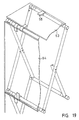
- FIG. 17 shows schematically a skeleton made up of several crossing pairs of rods, which can be folded up.
- This framework consists of individual frame units, as will be explained with reference to FIG. 18.
- a framework 1 can essentially consist of two crossing, flat and rectangular frames 17, the frame sides 18 forming the rod-shaped elements 2 crossing at the crossing points 16. The ends of the elements are connected to one another with the connecting elements already described.
- the framework can be fixed in a certain position, for example, by a stabilizing piece 41.
- the rod-shaped elements are referred to below only as tubes.
- a bore 42 is arranged through the entire tube.
- a plurality of bores are preferably provided in the central region of the tube, so that the two tubes can also cross outside their center.
- Either a snap joint 43 or a connecting screw 44 can be inserted into the bore 42.
- the snap joint consists of two parts, which can be pressed together like a push button. Both parts are provided with a bolt 45 which can be inserted into the bores 42 of the two tubes. Since the tubes of the frame 17 * are arranged on the inside of the frame 17, the two parts of the snap lock 43 remain pressed together and the bolts 45 cannot slip out.
- a connecting screw 44 is preferably used, the connection being secured with a locking nut 46.
- a locking nut 46 Between the two crossing tubes bearing discs 47 are arranged, one side of which is adapted to the outer jacket of the tube in order to ensure the greatest possible stability.
- the corner connection 48 corresponds, for example, approximately to the connection shown in FIG. 8, with spacer sleeves 49 also being able to be added as required. These spacer sleeves are particularly necessary to compensate for the thickness of a tube in the plane of two intersecting tubes.
- individual connecting rods 50 can be provided, the ends of which are provided with a snap-in pipe coupling 51. These pipe couplings can be snapped onto the corner of a frame as shown.
- a further connection possibility to a basic frame element results with a corner piece 52.
- This corner piece can be either fixed or designed as a hinge.
- FIG. 19 shows a framework construction constructed approximately according to FIG. 18, in which the frames are provided with trays 53 and with display boards 54. Clamps 55, which can be snapped onto the tubes, serve for fixing.
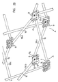
- FIGS. 20 and 21 framework structures are described in which the basic shape does not consist of intersecting planar frame pairs. Rather, individual pairs of rods or scissors 56 are connected to one another to form closed units with a polygonal grid.
- a closed unit consisting of the four scissors 56a, 56b, 56c and 56d, is shown in FIG.
- the ends of the scissors 56 are hinged together by means of the large core parts 9.
- the purpose of the two adjacent axis sections 12 and 12 ' is particularly clear. Since the individual tubes of the scissors 56 are each offset from one another by a tube thickness, a connection to an axle section 12 or 12 'is alternately required.
- Each closed unit can be folded into a structure in which all the bars of the individual scissors 56 run almost parallel to one another and are close to one another. Each individual pair of scissors performs a pivoting movement around the intersection 16, as indicated by the direction of arrow A.
- two core parts 9 are connected to a spacer tube 57.
- This can, as in FIG. 20 be connected to the axes 12 or, as shown in FIG. 21, in the center of the core parts 9.
- the spacer tube can be provided on both sides with the push button already mentioned.
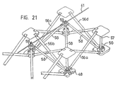
- FIG. 21 again shows a closed unit consisting of four scissors 56a, 56b, 56c, and 56d connected to one another, as has already been shown in FIG.
- the closed unit is reinforced with a pyramid-like rod structure, each rod 58 of this rod structure being connected to a connection point between two scissors.
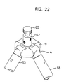
- the pyramid rods 58 meet at the pyramid tip 59 and are connected there to form a node, as is shown, for example, in FIG. 22.
- a further closed unit with a pyramid tip 59 ' is partially shown on the left side.
- the pyramid-like rod structures serve to reinforce the closed units in the horizontal plane, so that, for example, ceiling structures can be built.
- the adjacent pyramid tips 59, 59 'etc. are preferably connected to one another via a cable 61.
- the cable pull has the advantage that the entire framework can be folded up, the cable pull hanging loosely in the folded-up state.
- the length of the pyramid rods 58 must be selected such that they do not hinder the folding of the scissors 56.
- the pyramid tips on a ceiling construction can be directed either upwards or downwards or in both directions. The sag of a ceiling construction can be corrected with the cable pull 61.
- the pyramid tips also create a further connection level on which additional structures can be built using core parts.
- FIG. 22 shows a pyramid tip, the core part 9 being provided with a cable holder 62. A cable can be pulled into this and clamped with a locking screw 60.
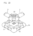
- FIG. 23 shows the combination of two core parts according to FIGS. 11 and 14.
- the small core part 63 is inserted into the large core part 64, the hexagonal flange 32 penetrating into the depression 30.
- the two parts 63 and 64 are non-positively connected to one another with a fastening screw, not shown.
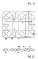
- FIGS. 24 and 25 show a construction with a horizontal extension consisting of a plurality of closed units 65 arranged in a row.
- the pyramid rods 58 are shown as broken lines.
- the cables 61 connect the neighboring pyramid tips in a straight line.
- skeleton constructions shown and described here are only individual examples. Obviously, an almost unlimited number of different room shapes with different basic grids can be constructed. So in particular dome-like structures can be erected, the z. B. can serve as emergency shelters with a suitable covering.
Landscapes
- Engineering & Computer Science (AREA)
- General Engineering & Computer Science (AREA)
- Mechanical Engineering (AREA)
- Architecture (AREA)
- Physics & Mathematics (AREA)
- Electromagnetism (AREA)
- Civil Engineering (AREA)
- Structural Engineering (AREA)
- Mutual Connection Of Rods And Tubes (AREA)
- Superconductors And Manufacturing Methods Therefor (AREA)
- Joining Of Building Structures In Genera (AREA)
- Variable-Direction Aerials And Aerial Arrays (AREA)
- Assembled Shelves (AREA)
- Prostheses (AREA)
- Rod-Shaped Construction Members (AREA)
- Grates (AREA)
- Manufacturing Of Tubular Articles Or Embedded Moulded Articles (AREA)
- Pit Excavations, Shoring, Fill Or Stabilisation Of Slopes (AREA)
Description
- Die Erfindung bezieht sich auf ein Gerippe bestehend aus stabförmigen Elementen gemäß dem Oberbegriff von Anspruch 1. Derartige Gerippe ermöglichen den raschen Aufbau einer Raumstruktur für die verschiedensten Zwecke. Sie werden heute beispielsweise in zunehmendem Masse im Ausstellungsbau für den Aufbau von Schauwänden oder für die Konstruktion ganzer Standaufbauten eingesetzt. Denkbar ist aber auch die Konstruktion von Möbeln oder von behelfsmäßigen Notunterkünften sowie von Kuppeln und dergleichen mehr.
- Gattunsmässig vergleichbare Gerippe sind beispielsweise durch die US-A-4 290 244 oder die WO-A-84 01 094 bekannt geworden. Bei den dort dargestellten und beschriebenen Konstruktionen sind die Verbindungselemente fest in die Enden der stabförmigen Elemente eingeprellt, wobei jeweils mehrere Verbindungselemente fest an einem Knotenpunkt angelenkt sind. Ein Rohrverbindungssystem mit austauschbaren Verbindungselementen ist durch die DE-A-2 024 508, die als nächstliegender Stand der Technik anzusehen ist, bekannt geworden. Die Rohrstücke weisen an ihren Enden wenigstens zwei Ausnehmungen auf und die Verbindungselemente haben mit Nasen versehene Spreizarme, welche in die Rohrstücke einsteckbar sind, wobei die Nasen in die Ausnehmungen einrasten. Zur Querverbindung mit einem anderen Rohr dient ein schellenartiges Teil, das an den Spreizarmen angeordnet ist.
- Dieses Verbindungssystem erlaubt zwar die Entfernung und den Austausch der Verbindungselemente, eignet sich aber nicht für die Bildung komplizierter Knotenpunkte an einem Gerippe.
- Es ist daher eine Aufgabe der Erfindung, ein Gerippe der eingangs genannten Art zu schaffen, bei dem die Verbindungselemente auf einfache Weise austauschbar sind, wobei mit diesen auch komplizierte Knotenpunkte rasch angeschlossen werden können. Außerdem sollen vielseitige Strukturen mit möglichst wenigen Einzelbauteilen realisiert werden können, wobei der Benützer die Einzelbauteile im Baukastenprinzip selber beliebig kombinieren kann. Diese Aufgabe wird erfindungsgemäß mit einem Gerippe gelöst, das die Merkmale in Anspruch 1 aufweist.
- Der in die Öffnung im Rohrmantel einrastbare Nocken am Schaft des Verbindungselementes erlaubt eine Entfernung des Verbindungselementes in jedem beliebigen Zustand. So können an einer bestehenden Konstruktion beispielsweise einzelne Rohre entfernt werden und gegen andere Rohre mit anderer Längenabmessung ausgetauscht werden. Wenn die stabförmigen Elemente Rohre sind, können diese sogar auf jedes beliebige Mass zugeschnitten werden, wobei lediglich noch die Öffnung im Rohrmantel an der richtigen Stelle zu bohren ist. Die Struktur läßt sich außerdem vollständig in ihre Einzelteile zerlegen, so daß beispielsweise die gleichen stabförmigen Elemente zum Bau unterschiedlicher Strukturen mit verschiedenen Verbindungselementen versehen werden können. Daraus ergibt sich ein Baukastensystem, das einerseits eine bestimmte Anzahl Typen stabförmiger Elemente und anderseits eine bestimmte Anzahl Typen Verbindungselemente aufweist. Der federnde Nocken wird zu einem separaten Bauteil, womit die Herstellung des Verbindungselements vereinfacht werden kann. Außerdem kann derart die gewünschte Federspannung je nach Ausbildung des Federelements beliebig gewählt werden und beschädigte Nocken lassen sich austauschen, ohne daß dabei das ganze Verbindungselement unbrauchbar wird. Es ist auch denkbar, das Federelement aus einem anderen Werkstoff als das übrige Verbindungselement zu fertigen.
- Die Funktion der Greifvorrichtung ist besonders effizient, weil die Verbindungselemente in der Ebene der Rohrachse geteilt ausgebildet sind und die Greifvorrichtung aus zwei Halbschalen besteht, die bei eingeschobenem Schaft geschlossen sind. Die Halbschalen können dabei sowohl sphärisch zum Ergreifen einer Kugel als auch hohlzylindrisch oder mit einem polygonen Querschnitt zum Ergreifen einer Achse ausgebildet sein. Ersichtlicherweise können die beiden Halbschalen um eine bestehende Achse oder Kugel geschlossen werden, so daß eine gelenkige oder drehfeste Verbindung entsteht, die jedoch jederzeit gelöst werden kann.
- Die Verbindungselemente können besonders rationell gefertigt und gehandhabt werden, wenn die beiden Hälften separate Teile sind, die an einem Ende mittels einer Einrastvorrichtung zusammensteckbar und derart scharnierartig miteinander verbunden sind. Bei richtiger Konfiguration können die beiden Hälften absolut identische Teile sein, die zu einem symmetrischen Körper zusammensteckbar sind. Die scharnierartige Verbindung an der Einrastvorrichtung verhindert, daß die beiden Hälften bei der Demontage auseinanderfallen. Außerdem wird bei richtiger Begrenzung des Öffnungswinkels ein Herausfallen des Federelements verhindert.
- Vielseitige Kombinationsmöglichkeiten für die stabförmigen Elemente ergeben sich, wenn die Greifvorrichtung an ein Kernteil anschließbar ist, das an seiner Außenseite mit Kupplungsmitteln versehen ist, welche formschlüssig in die Halbschalen passen. Auf diese Weise können mehrere Stäbe zu einem Knoten verbunden werden, wobei jeder einzelne Stab durch Öffnen der Greif-vorrichtung jederzeit entfernt werden kann.
- Wenn das Kernteil etwa viereckig ausgebildet ist und auf jeder Seite je zwei Achsabschnitte aufweist, von denen jeder eine Greifvorrichtung aufnehmen kann, lassen sich auf einer Seite zwei Stäbe anschließen. Dies erleichtert den Bau raumförmiger Gebilde sowie die Konstruktion faftbarer Gebilde mit sich kreuzenden Stäben.
- Vorzugsweise sind die sich scherenartig kreuzenden Elemente an ihren Kreuzungsstellen lösbar miteinander verbunden. Auf diese Weise läßt sich auch eine einzelne Schere vollständig zerlegen, so daß auch Scheren mit unterschiedlichen Stablängen zusammengebaut werden können.
- Weitere Vorteile können erzielt werden, wenn das Gerippe ein Grundelement aus zwei sich kreuzenden, planen und rechteckigen Rahmen aufweist, wobei jeweils parallele Rahmenseiten die sich scherenartig kreuzenden Elemente bilden. Eine beliebige Anzahl Anschlußelemente kann sich in allen drei Raumachsen auf die gleiche Weise an ein derartiges Grundelement anschließen, so daß ein Gerippe aus mehreren sich kreuzenden Rahmenebenen entsteht. Dieser Grundraster hat den Vorteil, daß er keine störenden Diagonalverbindungen zwischen sich kreuzenden Stabpaaren benötigt. Sowohl die einzelnen Rahmenebenen als auch die Ebenen zwischen den Seiten zweier benachbarter Rahmen bleiben dadurch für gestalterische Zwecke frei. In diesen Ebenen können Schautafeln, Tablare, Transparente usw. eingelegt bzw. eingespannt werden.
- Das Gerippe erhält eine besondere Stabilität und Verwindungssteifigkeit, wenn die stabförmigen Elemente Rohre sind, deren Mantel mit in Achsrichtung verlaufenden Rillen ausgebildet ist. Die Rillen verbessern außerdem das äußere Erscheinungsbild und machen die Rohre griffiger. Wenn der Rohrmantel im Querschnitt wellenförmig ausgebildet ist, wird damit die Dehnbarkeit der Rohrenden in Radialrichtung verbessert. Außerdem können die Schäfte der Verbindungselemente besser eingeführt werden, weil die Oberfläche des Innenmantels durch die Wellenform reduziert wird und damit eine geringere Reibung überwunden werden muß. Die Rillen auf der Außenseite haben auch noch den Vorteil, daß in Umfangsrichtung eine Rasterung gebildet wird, so daß z. B. Klemmen und dergleichen in einem bestimmten Winkel befestigt werden können.
- Weitere Vorteile und Einzelmerkmale der Erfindung ergeben sich aus der nachstehenden Beschreibung und aus den Zeichnungen. Die Zeichnungen zeigen verschiedene Ausführungsbeispiele, die nachstehend genauer beschrieben werden.
- Es zeigen:
- Figur 1 ein Verbindungselement mit aufgeklappter Greifvorrichtung vor dem Einschieben in ein Rohrende,
- Figur 2 das Verbindungselement gemäß Figur 1 im geschlossenen und in das Rohrende eingeschobenen Zustand,
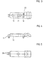
- Figur 3 eine Ansicht von unten auf die obere Hälfte des Verbindungselementes gemäß Figur 1,
- Figur 4 eine Seitenansicht auf das hälftige Verbindungselement gemäß Figur 3,
- Figur 5 eine Ansicht von oben auf das hälftige Verbindungselement gemäß Figur'3,
- Figur 6 ein abgewandeltes Ausführungsbeispiel eines Verbindungselementes im geöffneten und im geschlossenen Zustand,
- Figur 7 ein Verbindungselement zur Aufnahme einer Schraube,
- Figur 8 einen Querschnitt durch eine Verbindung von drei Rohrenden,
- Figuren ein abgewandeltes Ausführungsbeispiel 9 u. 10 eines Verbindungselements ohne Längsteilung,
- Figur 11 eine Draufsicht auf ein Kernteil,
- Figur 12 einen Querschnitt durch eine Kernteil-Hälfte durch die Ebene I - I gemäß Figur 11,
- Figur 13 einen Querschnitt durch das Kernteil in der Ebene 11 - 11 gemäß Figur 11,
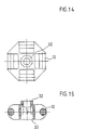
- Figur 14 ein kleines Kernteil,
- Figur 15 einen Querschnitt durch das Kernteil gemäß Figur 14,
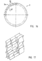
- Figur 16 eine Seitenansicht auf ein Rohrende mit Wellenmantel in stark vergrößertem Maßstab,
- Figur 17 ein Gerippe in schematischer Darstellung bestehend aus sich kreuzenden Rahmen,
- Figur 18 ein Grundelement mit verschiedenen Anschlußmöglichkeiten und Verbindungselementen in perspektivischer Darstellung,
- Figur 19 ein Grundelement mit an den Rahmenschenkeln befestigten Platten,
- Figur 20 ein Element aus vier miteinander verbundenen Stabpaaren,
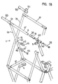
- Figur 21 vier miteinander verbundene Stabpaare mit pyramidenartiger Stabstruktur,
- Figur 22 eine Detaildarstellung einer Pyramidenspitze,
- Figur 23 eine Detaildarstellung eines Anschlusses der Pyramidenstäbe,
- Figur 24 eine Draufsicht auf eine Deckenkonstruktion mit viereckigem Grundraster,
- Figur 25 eine Seitenansicht der Konstruktion gemäß Figur 24.
- Für eine einwandfreie Positionierung der beiden Hälften ist an jeder Hälfte je ein Positionierbolzen 19 und eine Positionierbohrung 30 angeordnet. Bei den einander zugewandten Hälften 6 und 6' dringt jeweils der Positionierbolzen 19 in die gegenüberliegende Positionierbohrung 20. Im Schaft 3 des Verbindungselements ist eine Ausnehmung 10 vorgesehen, die an einer Stelle in eine Öffnung 21 übergeht. Die Ausnehmung 10 dient zur Aufnahme des Federelements 11, das im vorliegenden Ausführungsbeispiel als U-förmiger Bügel ausgebildet ist. Jedes Federelement trägt eiren Nocken 13, der im geschlossenen Zustand aus der Öffnung 21 ragt. Am unteren Schenkel des U-förmigen Bügels ist ein Positioniernocken 22 angeordnet, der jedoch nurteilweise in die Öffnung 21 eindringt und lediglich zur Positionierung des Federelements 11 dient.
- Jedes Verbindungselement ist mit einer Greifvorrichtung 14 versehen, die im vorliegenden Fall aus den beiden Halbschalen 5 und 5' besteht. Diese beiden Halbschalen sind so ausgebildet, daß sie eine Achse 12 formschlüssig ergreifen können. Eine umlaufende Schulter 37 begrenzt den Schaft 3, wobei die Schulter vorzugsweise eine Höhe aufweist, die etwa der Wandstärke der Rohre entspricht.
- Mit dem in den Figuren 1 und 2 dargestellten Verbindungselement 4 soll das stabförmige Element 2 mit seinem rohrförmigen Ende mit der Achse 12 verbunden werden. Das rohrförmige Element 2 ist mit einer Öffnung 8 versehen, deren Durchmesser etwas größer ist als der Durchmesser des Nockens 13. Das Verbindungselement wird nun so weit geöffnet, daß die beiden Halbschalen 5 und 5' die Achse 12 ergreifen können. Dann wird das Verbindungselement geschlossen, wobei der Nocken 13 aus der Öffnung 21 herausragt. Anschließend wird der Schaft 3 des geschlossenen Verbindungselementes in das Element 2 eingeschoben. Zu diesem Zweck wird der Nocken 13 nach innen gepreßt, bis er die Öffnung 8 erreicht, wo er infolge der Federwirkung einrastet, wie Figur 2 zeigt. Zum Entfernen des Verbindungselementes aus dem Element 2 muß der Nocken 13 wiederum nach innen gepreßt werden, so daß die Sperre gelöst wird. Dies kann auf einfachste Weise von Hand oder auch mit Hilfe eines Schraubenziehers oder dergleichen geschehen.
- Die Achse 12 bzw. die Halbschalen 5 könnten auch z. B. einen sechseckigen oder viereckigen Querschnitt aufweisen, so daß ein Drehen der Achse bei geschlossenem Verbindungselement nicht möglich wäre.
- In Figur 6 ist ein alternatives Ausführungsbeispiel eines Verbindungselementes 4 dargestellt, welches zwar ebenfalls hälftig geteilt ist, bei dem die beiden Hälften jedoch an einem Scharnier 23 miteinander verbunden sind. Das Scharnier 23 kann beispielsweise durch einen dünnen Materialfilm gebildet sein. Die beiden Hälften werden durch einen Druckknopf 24 zusammengehalten, der in die benachbarte Druckknopföffnung 25 einpreßbar ist. Auch hier ist das Federelement 11 in die Ausnehmung 10 eingeschlossen und kann nur bei geöffnetem Verbindungselement entfernt werden.
- In Figur 7 ist ein Verbindungselement dargestellt, das als Schraubenklammer 38 ausgebildet ist. Diese besteht ebenfalls aus den beiden Hälften 6 und 6', die an einem Ende scharnierartig miteinander verbunden sind. Bei diesem Schraubengreifer wird keine separate Sperrklinke eingelegt. Der Nocken 13 ist fest an der oberen Hälfte 6 angeordnet. Die Federspannung wird durch die beiden Hälften erzeugt, welche die Tendenz haben, sich zu öffnen. In den beiden Hälften 6 und 6' ist in Axialrichtung eine Gewindebohrung 27 angeordnet, in die im geschlossenen Zustand eine Schraube 26 eingeschraubt werden kann. Anstelle der Gewindegänge könnten auch nur einzelne Rippen oder Nocken vorgesehen sein, welche die Schraube oder einen ebenfalls gerippten Bolzen festhalten, der eingeprellt wird.
- In Figur 8 ist ein Querschnitt durch eine typische Kombination von Verbindungselementen dargestellt. Eine derartige Kombination ergibt sich in der Regel am Ecken eines einzelnen Rahmens einer Gerippekonstruktion. In ein horizontal verlaufendes Rohrelement 2 ist eine Schraubenklammer 38 eingesetzt. Diese ist etwa wie in Figur 7 ausgebildet und hat als Greifvorrichtung lediglich eine axial verlaufende Bohrung 39. Im vertikal verlaufenden Rohr 2' ist ein Verbindungselement 4 eingeschoben, dessen Greifvorrichtung teilweise in die Bohrung 39 des Schraubengreifers 38 eindringt. Ein weiteres vertikales, jedoch nach oben gerichtetes Rohr 2" ist dadurch an die Verbindungsstelle angeschlossen, daß auch in dieses Rohr ein Verbindungselement 4' eingeschoben ist, das teilweise in die Bohrung des Verbindungselements 4 eindringt. Die gesamte Verbindung wird durch eine Imbußchraube 26 zusammengehalten, welche in die Gewindebohrung des Schraubengreifers 38 eingeschraubt ist. Ersichtlicherweise können auch bei angezogener Schraube 26 die Rohre 2' und 2" seitlich verschwenkt werden, so daß eine gelenkige Verbindung entsteht.
- In den Figuren 9 und 10 ist ein afternatives Ausführungsbeispiel eines Verbindungselements dargestellt, welches nicht in zwei Hälften geteilt, sondern einstückig ausgebildet ist. Die Ausnehmung 10 ist auf einer Seite offen, so daß das eingelegte Federelement 11 mit dem Nocken 13 im eingeschobenen Zustand durch die Wandung des Rohrs 2 abgestützt wird. Die Greifvorrichtung 14 ist als einfache Durchgangsbohrung ausgebildet, welche quer zur Rohrachse verläuft. Vorzugsweise sind zwei Bohrungen von verschiedenem Durchmesser angeordnet, so daß beispielsweise ein Schraubenkopf versenkt werden kann, wie in Figur 8 dargestellt.
- Die Figuren 11 bis 13 zeigen ein Kernteil 9, an das mehrere stabförmige Elemente angeschlossen werden können. Aus fabrikationstechnischen Gründen ist dieses Teil ebenfalls in zwei Hälften geteilt, die formgleich ausgebildet sind und ineinander gesteckt werden können, wie insbesondere Figur 13 zeigt. Zu diesem Zweck sind auf der Innenseite sich diametral gegenüberliegende Zapfen 28 und Bohrungen 29 vorgesehen. Am Umfangsbereich des Teils 9 sind auf jeder Seite je zwei Achsabschnitte 12 und 12' angeordnet, deren Breite jeweils der Breite einer Greifvorrichtung entspricht. Im Zentrum ist eine Vertiefung 30 vorgesehen, die beispielsweise einen hexagonalen Körper drehfest aufnehmen kann. Das Durchgangsloch 31 und die Bohrungen 66 dienen zur Aufnahme einer Schraube zum Verbinden des Kernteils mit anderen Bauteilen.
- Anstelle von Schrauben könnte auch ein Druckknopf 67 verwendet werden, dessen zwei federnde Nasen 68 zusammenpreßbar sind. Der gleiche Druckknopf könnte auch durch die geschlossenen Halbschalen eines Verbindungselements gesteckt werden.
- In den Figuren 14 und 15 ist ein anderer Typ eines Kernteils dargestellt, welches etwas kleiner ist und an jeder Seite nur einen einzigen Achsabschnitt 12 aufweist. Auf einer Seite ist ein Sechskantflansch 32 angeordnet, der formschlüssig in die Vertiefung 30 des Kernteils gemäß Figur 11 paßt. Die Vertiefung 33 dient zur Aufnahme eines Schraubenkopfes. Selbstverständlich können die Kernteile auch andere Konfigurationen aufweisen und beispielsweise sechseckig, dreieckig oder auch als Polyeder ausgebildet sein.
- Figur 16 zeigt eine bevorzugte Querschnittskonfiguration eines stabförmigen Elements 2. Der Rohrmantel 34 ist in Längsrichtung mit einzelnen Rillen 35 versehen. Der Rohrmantel ist dabei vorzugsweise über dem ganzen Umfang mit einzelnen Wellen 40 versehen, womit eine gewisse Elastizität in Radialrichtung erzielt wird. Gleichzeitig wird aber auch die Verwindungssteifigkeit und die Knickfestigkeit in Axialrichtung erhöht.
- Figur 17 zeigt schematisch ein aus mehreren sich kreuzenden Stabpaaren aufgebautes Gerippe, welches zusammenklappbar ist. Dieses Gerippe besteht aus einzelnen Rahmeneinheiten, wie anhand von Figur 18 erläutert wird.
- Ein Gerippe 1 kann dabei im wesentlichen aus zwei sich kreuzenden, planen und rechteckigen Rahmen 17 bestehen, wobei die Rahmenseiten 18 die sich an den Kreuzungsstellen 16 kreuzenden stabförmigen Elemente 2 bilden. Die Enden der Elemente sind mit den bereits beschriebenen Verbindungselementen miteinander verbunden. Das Gerippe kann beispielsweise durch ein Stabilisierungsstück 41 in einer bestimmten Position fixiert werden. Die stabförmigen Elemente werden nachstehend der Einfachheit halber nur noch als Rohre bezeichnet. An der Kreuzungsstelle 16 ist eine durch das ganze Rohr gehende Bohrung 42 angeordnet. Wie in der Zeichnung angedeutet, sind im Mittelbereich des Rohres vorzugsweise mehrere Bohrungen vorgesehen, so daß sich die beiden Rohre auch außerhalb ihrer Mitte kreuzen können. In die Bohrung 42 kann entweder ein Schnappgelenk 43 oder eine Verbindungsschraube 44 eingesetzt werden. Das Schnappgelenk besteht aus zwei Teilen, welche druckknopfartig zusammengepreßt werden können. Beide Teile sind mit einem Bolzen 45 versehen, der in die Bohrungen 42 der beiden Rohre eingesteckt werden kann. Da die Rohre des Rahmens 17* auf der Innenseite des Rahmens 17 angeordnet sind, bleiben die beiden Teile des Schnappverschlusses 43 zusammengepreßt und die Bolzen 45 können nicht herausrutschen.
- Wenn die Kreuzungsstellen 16 einer größeren mechanischen Belastung ausgesetzt sind, wird vorzugsweise eine Verbindungsschraube 44 eingesetzt, wobei die Verbindung mit einer Sperrmutter 46 gesichert wird. Zwischen den beiden sich kreuzenden Rohren sind Lagerscheiben 47 angeordnet, deren eine Seite dem Außenmantel des Rohres angepaßt ist, um eine größtmögliche Stabilität zu gewährleisten.
- Die Eckverbindung 48 entspricht beispielsweise etwa der in Figur 8 dargestellten Verbindung, wobei je nach Bedarf auch noch Distanzhülsen 49 hinzugefügt werden können. Diese Distanzhülsen sind insbesondere erforderlich, um in der Ebene zweier sich kreuzender Rohre die Dicke eines Rohres zu kompensieren.
- Zum Verbinden einzelner Gerippeteile mit einem anderen Gerippe können einzelne Verbindungsstäbe 50 vorgesehen sein, deren Enden mit einer einrastbaren Rohrkupplung 51 versehen sind. Diese Rohrkupplungen können wie dargestellt auf die Ecke eines Rahmens aufgeschnappt werden.
- Eine weitere Anschlußmöglichkeit an ein Rahmengrundelement ergibt sich mit einem Eckstück 52. Dieses Eckstück kann entweder fest oder als Scharnier ausgebildet sein.
- Figur 19 zeigt eine etwa gemäß Figur 18 aufgebaute Gerippekonstruktion, bei der die Rahmen mit Tablaren 53 und mit Schautafeln 54 versehen sind. Zur Fixierung dienen dabei Klammern 55, welche auf die Rohre aufgeschnappt werden können.
- In den Figuren 20 und 21 sind Gerippestrukturen beschrieben, bei denen die Grundform nicht aus sich kreuzenden ebenen Rahmenpaaren besteht. Vielmehr sind einzelne Stabpaare oder Scheren 56 zu geschlossenen Einheiten mit polygonem Raster miteinander verbunden. In Figur 20 ist eine derartige geschlossene Einheit, bestehend aus den vier Scheren 56a, 56b, 56c und 56d dargestellt. Die Enden der Scheren 56 sind mittels der großen Kernteile 9 gelenkig miteinander verbunden. Hier wird der Zweck der beiden nebeneinander liegenden Achsabschnitte 12 und 12' besonders deutlich. Da die einzelnen Rohre der Scheren 56 jeweils um eine Rohrstärke versetzt zueinander sind, ist wechselweise ein Anschluß an einem Achsabschnitt 12 oder 12' erforderlich. Jede geschlossene Einheit kann zu einem Gebilde zusammengefaltet werden, bei dem alle Stäbe der einzelnen Scheren 56 beinahe parallel zueinander verlaufen und nahe beieinander liegen. Jede einzelne Schere führt dabei um die Kreuzungsstelle 16 eine Schwenkbewegung aus, wie sie mit Pfeilrichtung A angedeutet ist.
- Zur Stabilisierung einer geschlossenen Einheit werden zwei Kernteile 9 mit einem Distanzrohr 57 verbunden. Dieses kann, wie in Figur 20 an den Achsen 12 oder, wie in Figur 21 dargestellt, im Zentrum der Kernteile 9 angeschlossen werden. Das Distanzrohr kann auf beiden Seiten mit dem bereits erwähnten Druckknopf versehen sein.
- In Figur 21 ist wiederum eine geschlossene Einheit aus vier miteinander verbundenen Scheren 56a, 56b 56c, und 56d dargestellt, wie bereits in Figur 20 gezeigt wurde. Die geschlossene Einheit ist jedoch mit einer pyramidenartigen Stabstruktur verstärkt, wobei jeder Stab 58 dieser Stabstruktur an einer Verbindungsstelle zweier Scheren angeschlossen ist. Die Pyramidenstäbe 58 treffen sich an der Pyramidenspitze 59 und sind dort zu einem Knoten verbunden, wie dies beispielsweise in Figur 22 dargestellt ist. In Figur 21 ist auf der linken Seite eine weitere geschlossene Einheit mit einer Pyramidenspitze 59' teilweise dargestellt. Die pyramidenartigen Stabstrukturen dienen dazu, die geschlossenen Einheiten in der horizontalen Ebene zu verstärken, so daß beispielsweise Deckenkonstruktionen gebaut werden können. Vorzugsweise werden die benachbarten Pyramidenspitzen 59, 59' usw. über einen Seilzug 61 miteinander verbunden. Anstelle des Seilzugs kann selbstverständlich auch ein weiterer Stab oder eine Fläche verwendet werden. Der Seilzug hat jedoch den Vorteil, daß das gesamte Gerippe zusammengefaltet werden kann, wobei der Seilzug im zusammengefalteten Zustand lose herunterhängt. Ersichtlicherweise muß die Länge der Pyramidenstäbe 58 derart gewählt werden, daß sie das Zusammenfalten der Scheren 56 nicht behindern. Die Pyramidenspitzen können an einer Deckenkonstruktion sowohl nach oben als auch nach unten oder nach beiden Richtungen gerichtet sein. Mit dem Seilzug 61 kann der Durchhang einer Dekkenkonstruktion korrigiert werden. Die Pyramidenspitzen schaffen zudem eine weitere Anschlußebene, auf der mittels Kernteilen weitere Strukturen aufgebaut werden können.
- Figur 22 zeigt eine Pyramidenspitze, wobei das Kernteil 9 mit einer Seilzughalterung 62 versehen ist. In diese kann ein Seilzug durchgeführt und mit einer Feststellschraube 60 festgeklemmt werden.
- Figur 23 zeigt die Kombination zweier Kernteile gemäß den Figuren 11 und 14. Das kleine Kernteil 63 wird dabei in das große Kernteil 64 eingesteckt, wobei der Sechskantflansch 32 in die Vertiefung 30 eindringt. Mit einer nicht dargestellten Befestigungsschraube werden die beiden Teile 63 und 64 kraftschlüssig miteinander verbunden.
- Die Figuren 24 und 25 zeigen eine Konstruktion mit horizontaler Ausdehnung bestehend aus mehreren aneinander gereihten geschlossenen Einheiten 65. Die Pyramidenstäbe 58 sind als unterbrochene Linien dargestellt. Die Seilzüge 61 verbinden die benachbarten Pyramidenspitzen geradlinig miteinander.
- Die hier dargestellten und beschriebenen Gerippekonstruktionen stellen lediglich Einzelbeispiele dar. Ersichtlicherweise kann eine beinahe unbeschränkte Zahl von verschiedenen Raumformen mit unterschiedlichem Grundraster aufgebaut werden. So können insbesondere auch kuppelartige Gebilde errichtet werden, die z. B. mit einer geeigneten Bespannung als Notunterkünfte dienen können.
Wie in den Figuren 1 bis 5 dargestellt, besteht ein typisches Verbindungselement 4 aus den beiden Hälften 6 und 6', welche vorzugsweise absolut identisch ausgebildet sind. Die Verbindungselemente werden vorzugsweise aus Kunststoffmaterial im Spritzgußverfahren hergestellt. Die beiden Hälften 6 und 6' werden an einer Einrastvorrichtung 7 zusammengesteckt, so daß sie scharnierartig geöffnet und geschlossen werden können. Wie insbesondere aus den Figuren 3 bis 5 ersichtlich ist, besteht die Einrastvorrichtung aus zwei Wangen 36, welche asymmetrisch zur Mittelachse angeordnet sind und von denen wenigstens eine nach unten verlängert ist, wie aus Figur 4 ersichtlich ist. Auf der Innenseite der Wangen ist je ein Nocken bzw. eine Vertiefung vorgesehen, so daß zwei ineinander geschobene Wangenpaare ineinander einrasten. Die Wangen sind dabei derart ausgebildet, daß sich die beiden Hälften 6 und 6' nur bis zu einem bestimmten Winkel öffnen können, was die Handhabung vereinfacht und zudem verhindert, daß das Federelement herausfallen kann.
Claims (13)
Priority Applications (1)
| Application Number | Priority Date | Filing Date | Title |
|---|---|---|---|
| AT86906748T ATE51274T1 (de) | 1985-12-02 | 1986-11-25 | Gerippe bestehend aus stabfoermigen elementen. |
Applications Claiming Priority (2)
| Application Number | Priority Date | Filing Date | Title |
|---|---|---|---|
| CH515285 | 1985-12-02 | ||
| CH5152/85 | 1985-12-02 |
Related Child Applications (1)
| Application Number | Title | Priority Date | Filing Date |
|---|---|---|---|
| EP89115135.9 Division-Into | 1989-08-17 |
Publications (2)
| Publication Number | Publication Date |
|---|---|
| EP0249601A1 EP0249601A1 (de) | 1987-12-23 |
| EP0249601B1 true EP0249601B1 (de) | 1990-03-21 |
Family
ID=4288806
Family Applications (2)
| Application Number | Title | Priority Date | Filing Date |
|---|---|---|---|
| EP86906748A Expired - Lifetime EP0249601B1 (de) | 1985-12-02 | 1986-11-25 | Gerippe bestehend aus stabförmigen elementen |
| EP89115135A Expired - Lifetime EP0346948B1 (de) | 1985-12-02 | 1986-11-25 | Gerippe bestehend aus stabförmigen Elementen |
Family Applications After (1)
| Application Number | Title | Priority Date | Filing Date |
|---|---|---|---|
| EP89115135A Expired - Lifetime EP0346948B1 (de) | 1985-12-02 | 1986-11-25 | Gerippe bestehend aus stabförmigen Elementen |
Country Status (9)
| Country | Link |
|---|---|
| US (1) | US4829735A (de) |
| EP (2) | EP0249601B1 (de) |
| JP (1) | JPH0723626B2 (de) |
| AT (1) | ATE100166T1 (de) |
| AU (1) | AU585676B2 (de) |
| CA (1) | CA1290546C (de) |
| DE (2) | DE3689546D1 (de) |
| ES (1) | ES2003954A6 (de) |
| WO (1) | WO1987003346A1 (de) |
Cited By (1)
| Publication number | Priority date | Publication date | Assignee | Title |
|---|---|---|---|---|
| DE102016002899A1 (de) | 2016-03-09 | 2017-09-14 | Johannes Kraus | (Naturzug)Feuerraum mit verbessertem Ausbrand |
Families Citing this family (17)
| Publication number | Priority date | Publication date | Assignee | Title |
|---|---|---|---|---|
| DE8717713U1 (de) * | 1987-09-17 | 1989-10-12 | Wolf, Elmar, 8706 Höchberg | Gitterwerk aus Stäben und Knoten |
| IT1213606B (it) * | 1987-09-18 | 1989-12-29 | Quattrocchio Srl | Dispositivo di giunzione e collegamento particolarmente per strutture modulari a traliccio |
| DE3868822D1 (de) * | 1987-09-29 | 1992-04-09 | Lanz Oensingen Ag | Variable montagerahmen-anordnung. |
| SE8801224D0 (sv) * | 1988-04-05 | 1988-04-05 | Curth Danielsson | Kopplingsanordning samt sett for dess framstellning |
| US5161344A (en) * | 1990-01-15 | 1992-11-10 | Expand International Ab | Portable display structure |
| DE4203838A1 (de) * | 1992-02-10 | 1993-08-12 | Markus Jehs | Traggeruest in gitterbauweise, insb. fuer ausstellungen und veranstaltungen |
| US5491991A (en) * | 1993-07-08 | 1996-02-20 | Guillory; Samuel L. | Security device for an automobile |
| DE9417425U1 (de) * | 1994-10-31 | 1995-01-19 | Rosing, Adolf, 93047 Regensburg | Verbindungselement für rohrförmige Gegenstände |
| US5943837A (en) * | 1996-01-30 | 1999-08-31 | Tvi Corporation | Quick erect shelter apparatus |
| CN1284194A (zh) | 1997-07-29 | 2001-02-14 | 国际英泰克斯展览有限公司 | 便携式显示系统 |
| US6244011B1 (en) | 1998-09-21 | 2001-06-12 | Tvi Corporation | Inverted V-shaped display framework |
| US20040188667A1 (en) * | 2002-01-12 | 2004-09-30 | Spur Innovation, Inc. | Portable collapsible corral fence |
| US20030213513A1 (en) * | 2002-05-17 | 2003-11-20 | Eriksen Steen Mandsfelt | Expandable framework structure for a canopy |
| JP5123566B2 (ja) * | 2007-05-25 | 2013-01-23 | 株式会社 コーゲイ | 折り畳みパイプ棚用管継手 |
| CN102537194B (zh) * | 2011-11-11 | 2013-10-30 | 江苏科技大学 | 一种用于外螺纹轴杆的快速连接装置 |
| US10753119B2 (en) | 2017-03-14 | 2020-08-25 | S & S Structures, Inc. | Portable structure with solar shade |
| US11142906B2 (en) * | 2018-07-06 | 2021-10-12 | Creative Tent International, Llc | Semi-permanent relocatable structure system |
Family Cites Families (15)
| Publication number | Priority date | Publication date | Assignee | Title |
|---|---|---|---|---|
| US1322801A (en) * | 1919-11-25 | lewis | ||
| US2762639A (en) * | 1953-01-07 | 1956-09-11 | Molter Ralph Marcy | Joint connections for framing systems |
| US2941294A (en) * | 1958-06-18 | 1960-06-21 | Peter S Vosbikian | Handles for manual tools with means to interlock with the shank of a working tool |
| FR1418868A (fr) * | 1964-07-03 | 1965-11-26 | Vallourec | Dispositif d'assemblage de tubes ou organes analogues |
| DE2024508A1 (de) * | 1970-05-20 | 1971-12-16 | Hanning Kunststoffe R Hanning | Rohrverbindungssystem |
| FR2251228A5 (en) * | 1973-11-14 | 1975-06-06 | Barrellon Pierre | Device for joining tubes of of tubular framework - arms on split ring around tube are pressed together and into second tube |
| FR2331745A1 (fr) * | 1975-11-14 | 1977-06-10 | Vuarnesson Bernard | Noeud d'assemblage polyedrique |
| US4290244A (en) * | 1976-07-13 | 1981-09-22 | Zeigler Theodore Richard | Collapsible self-supporting structures and panels and hub therefor |
| DE7820267U1 (de) * | 1978-07-06 | 1979-02-15 | Ruether, Hubert, Dipl.-Ing., 2105 Seevetal | Steckverbinder mit Verbindungsrohr und einer gesicherten, lösbaren Steckverbindung beider |
| ATE23059T1 (de) * | 1981-11-26 | 1986-11-15 | Hestex Systems Bv | Einschiebbares klemmschloss zur loesbaren verbindung von zwei bauelementen. |
| US4522008A (en) * | 1982-08-19 | 1985-06-11 | Zeigler Theodore Richard | Clip for self-locking collapsible/expandable structures |
| WO1984001094A1 (en) * | 1982-09-24 | 1984-03-29 | Preben Noedskov | A collapsible exhibit panel |
| GB8330122D0 (en) * | 1983-11-11 | 1983-12-21 | Stephenson C J S | Connector for framework structure |
| FR2563293B1 (fr) * | 1984-04-18 | 1987-10-02 | Technal France | Piece de jonction pour assembler avec serrage deux profiles, notamment equerre pour assemblage d'onglet et embout pour assemblage en bout |
| US4580922A (en) * | 1984-12-17 | 1986-04-08 | General Electric Co. | Vertex fittings derived from a master fitting |
-
1986
- 1986-11-25 WO PCT/CH1986/000163 patent/WO1987003346A1/de not_active Ceased
- 1986-11-25 JP JP61506023A patent/JPH0723626B2/ja not_active Expired - Lifetime
- 1986-11-25 EP EP86906748A patent/EP0249601B1/de not_active Expired - Lifetime
- 1986-11-25 EP EP89115135A patent/EP0346948B1/de not_active Expired - Lifetime
- 1986-11-25 AU AU66244/86A patent/AU585676B2/en not_active Ceased
- 1986-11-25 US US07/095,538 patent/US4829735A/en not_active Expired - Fee Related
- 1986-11-25 DE DE89115135T patent/DE3689546D1/de not_active Expired - Fee Related
- 1986-11-25 DE DE8686906748T patent/DE3669757D1/de not_active Expired - Fee Related
- 1986-11-28 CA CA000524142A patent/CA1290546C/en not_active Expired - Lifetime
- 1986-12-01 ES ES8603257A patent/ES2003954A6/es not_active Expired
-
1989
- 1989-08-17 AT AT89115135T patent/ATE100166T1/de not_active IP Right Cessation
Cited By (2)
| Publication number | Priority date | Publication date | Assignee | Title |
|---|---|---|---|---|
| DE102016002899A1 (de) | 2016-03-09 | 2017-09-14 | Johannes Kraus | (Naturzug)Feuerraum mit verbessertem Ausbrand |
| DE102016002899B4 (de) * | 2016-03-09 | 2020-03-12 | Johannes Kraus | Feuerraum mit verbessertem Ausbrand |
Also Published As
| Publication number | Publication date |
|---|---|
| AU585676B2 (en) | 1989-06-22 |
| JPH0723626B2 (ja) | 1995-03-15 |
| WO1987003346A1 (fr) | 1987-06-04 |
| AU6624486A (en) | 1987-07-01 |
| EP0346948A2 (de) | 1989-12-20 |
| ATE100166T1 (de) | 1994-01-15 |
| EP0346948A3 (en) | 1990-05-09 |
| EP0249601A1 (de) | 1987-12-23 |
| US4829735A (en) | 1989-05-16 |
| EP0346948B1 (de) | 1994-01-12 |
| ES2003954A6 (es) | 1988-12-01 |
| JPS63502363A (ja) | 1988-09-08 |
| DE3669757D1 (de) | 1990-04-26 |
| DE3689546D1 (de) | 1994-02-24 |
| CA1290546C (en) | 1991-10-15 |
Similar Documents
| Publication | Publication Date | Title |
|---|---|---|
| EP0249601B1 (de) | Gerippe bestehend aus stabförmigen elementen | |
| EP0393090B1 (de) | Bausatz zur herstellung von tragwerken | |
| DE69511133T2 (de) | Bausatz für ein Möbelsystem, insbesondere für Büros, mit selbsttragenden, multifunktionellen Tragsäulen | |
| EP3721029B1 (de) | Vorrichtung mit einem träger und zwei stiel-anschluss-adapter für gerüst | |
| DE3704831C2 (de) | ||
| EP0144030A2 (de) | Profilrohr für die Herstellung von leicht montier- und wieder demontierbaren Aufbauten | |
| DE1803090A1 (de) | Rahmengestell | |
| EP0099972B1 (de) | Verbindungselement für Platten | |
| DE2815243A1 (de) | Schalentragwerk aus knotenpunktverbindungen und tragwerksstaeben sowie verfahren zur errichtung desselben | |
| EP0956402B1 (de) | Tragwerk mit verbindungsknoten und streben | |
| EP0182288B1 (de) | Raumkonstruktion | |
| EP0398068B1 (de) | Trägerverbindung | |
| DE102007014263B3 (de) | Verbindungsknoten für ein zwei- oder dreimensionales Tragwerk | |
| WO2013060470A1 (de) | Tragvorrichtung für eine möbelvorrichtung, insbesondere für einen raumteiler | |
| DE4304602C2 (de) | Verbindungsknoten | |
| DE2711903A1 (de) | Vorgefertigtes bauelement zum errichten von gitterartigen waenden, einfriedungen, gestellen, geruesten, masten oder dergleichen | |
| AT526842B1 (de) | Rechtwinkelige Fachwerk-Struktur mit hoher Stabilität und Gestaltungsfreiheit, als Raumgliederung oder Regal | |
| DE2709465C3 (de) | Knotenpunkt für eine Skelettkonstruktion | |
| DE2728021A1 (de) | Knotenpunktverbindung fuer staebe | |
| DE4414759A1 (de) | Gestell für die Lagerung von länglichen Gegenständen sowie Profilelement für den Aufbau eines solchen Gestells | |
| DE3942122A1 (de) | Tragkonstruktion, insbesondere fuer leicht montier- und demontierbare messebauten | |
| DE202018104489U1 (de) | Modulare Stellwand und Verwendung der modularen Stellwand | |
| DE8704312U1 (de) | Faltwand | |
| DE3734533A1 (de) | Knotenpunktsystem fuer messestandkonstruktionen und aehnliche aufbauten aus hohlprofilstaeben | |
| DE10206258A1 (de) | Gestellsystem |
Legal Events
| Date | Code | Title | Description |
|---|---|---|---|
| PUAI | Public reference made under article 153(3) epc to a published international application that has entered the european phase |
Free format text: ORIGINAL CODE: 0009012 |
|
| 17P | Request for examination filed |
Effective date: 19870714 |
|
| AK | Designated contracting states |
Kind code of ref document: A1 Designated state(s): AT BE CH DE FR GB IT LI LU NL SE |
|
| 17Q | First examination report despatched |
Effective date: 19880610 |
|
| ITF | It: translation for a ep patent filed | ||
| GRAA | (expected) grant |
Free format text: ORIGINAL CODE: 0009210 |
|
| AK | Designated contracting states |
Kind code of ref document: B1 Designated state(s): AT BE CH DE FR GB IT LI LU NL SE |
|
| REF | Corresponds to: |
Ref document number: 51274 Country of ref document: AT Date of ref document: 19900415 Kind code of ref document: T |
|
| REF | Corresponds to: |
Ref document number: 3669757 Country of ref document: DE Date of ref document: 19900426 |
|
| ET | Fr: translation filed | ||
| GBT | Gb: translation of ep patent filed (gb section 77(6)(a)/1977) | ||
| PG25 | Lapsed in a contracting state [announced via postgrant information from national office to epo] |
Ref country code: LU Free format text: LAPSE BECAUSE OF NON-PAYMENT OF DUE FEES Effective date: 19901130 |
|
| PLBE | No opposition filed within time limit |
Free format text: ORIGINAL CODE: 0009261 |
|
| STAA | Information on the status of an ep patent application or granted ep patent |
Free format text: STATUS: NO OPPOSITION FILED WITHIN TIME LIMIT |
|
| 26N | No opposition filed | ||
| ITTA | It: last paid annual fee | ||
| EAL | Se: european patent in force in sweden |
Ref document number: 86906748.8 |
|
| REG | Reference to a national code |
Ref country code: FR Ref legal event code: TP |
|
| REG | Reference to a national code |
Ref country code: GB Ref legal event code: 732E |
|
| NLS | Nl: assignments of ep-patents |
Owner name: ORIGON PRAESENTATIONSSYSTEME GMBH |
|
| PGFP | Annual fee paid to national office [announced via postgrant information from national office to epo] |
Ref country code: AT Payment date: 20000926 Year of fee payment: 15 |
|
| PGFP | Annual fee paid to national office [announced via postgrant information from national office to epo] |
Ref country code: CH Payment date: 20010122 Year of fee payment: 15 |
|
| PGFP | Annual fee paid to national office [announced via postgrant information from national office to epo] |
Ref country code: BE Payment date: 20011001 Year of fee payment: 16 |
|
| PGFP | Annual fee paid to national office [announced via postgrant information from national office to epo] |
Ref country code: SE Payment date: 20011008 Year of fee payment: 16 |
|
| PGFP | Annual fee paid to national office [announced via postgrant information from national office to epo] |
Ref country code: GB Payment date: 20011102 Year of fee payment: 16 |
|
| PG25 | Lapsed in a contracting state [announced via postgrant information from national office to epo] |
Ref country code: AT Free format text: LAPSE BECAUSE OF NON-PAYMENT OF DUE FEES Effective date: 20011125 |
|
| PGFP | Annual fee paid to national office [announced via postgrant information from national office to epo] |
Ref country code: FR Payment date: 20011128 Year of fee payment: 16 |
|
| PG25 | Lapsed in a contracting state [announced via postgrant information from national office to epo] |
Ref country code: LI Free format text: LAPSE BECAUSE OF NON-PAYMENT OF DUE FEES Effective date: 20011130 Ref country code: CH Free format text: LAPSE BECAUSE OF NON-PAYMENT OF DUE FEES Effective date: 20011130 |
|
| PGFP | Annual fee paid to national office [announced via postgrant information from national office to epo] |
Ref country code: NL Payment date: 20011130 Year of fee payment: 16 |
|
| REG | Reference to a national code |
Ref country code: GB Ref legal event code: IF02 |
|
| REG | Reference to a national code |
Ref country code: CH Ref legal event code: PL |
|
| PG25 | Lapsed in a contracting state [announced via postgrant information from national office to epo] |
Ref country code: GB Free format text: LAPSE BECAUSE OF NON-PAYMENT OF DUE FEES Effective date: 20021125 |
|
| PG25 | Lapsed in a contracting state [announced via postgrant information from national office to epo] |
Ref country code: SE Free format text: LAPSE BECAUSE OF NON-PAYMENT OF DUE FEES Effective date: 20021126 |
|
| PG25 | Lapsed in a contracting state [announced via postgrant information from national office to epo] |
Ref country code: BE Free format text: LAPSE BECAUSE OF NON-PAYMENT OF DUE FEES Effective date: 20021130 |
|
| PGFP | Annual fee paid to national office [announced via postgrant information from national office to epo] |
Ref country code: DE Payment date: 20030122 Year of fee payment: 17 |
|
| BERE | Be: lapsed |
Owner name: ORIGON PR?SENTATIONSSYSTEME G.M.B.H. Effective date: 20021130 |
|
| PG25 | Lapsed in a contracting state [announced via postgrant information from national office to epo] |
Ref country code: NL Free format text: LAPSE BECAUSE OF NON-PAYMENT OF DUE FEES Effective date: 20030601 |
|
| EUG | Se: european patent has lapsed | ||
| GBPC | Gb: european patent ceased through non-payment of renewal fee | ||
| PG25 | Lapsed in a contracting state [announced via postgrant information from national office to epo] |
Ref country code: FR Free format text: LAPSE BECAUSE OF NON-PAYMENT OF DUE FEES Effective date: 20030731 |
|
| NLV4 | Nl: lapsed or anulled due to non-payment of the annual fee |
Effective date: 20030601 |
|
| REG | Reference to a national code |
Ref country code: FR Ref legal event code: ST |
|
| PG25 | Lapsed in a contracting state [announced via postgrant information from national office to epo] |
Ref country code: DE Free format text: LAPSE BECAUSE OF NON-PAYMENT OF DUE FEES Effective date: 20040602 |
|
| PG25 | Lapsed in a contracting state [announced via postgrant information from national office to epo] |
Ref country code: IT Free format text: LAPSE BECAUSE OF NON-PAYMENT OF DUE FEES Effective date: 20051125 |