EP0247328B1 - Chaise tournante et réglable en hauteur, comportant un ressort pneumatique, notamment chaise ou fauteuil de bureau - Google Patents
Chaise tournante et réglable en hauteur, comportant un ressort pneumatique, notamment chaise ou fauteuil de bureau Download PDFInfo
- Publication number
- EP0247328B1 EP0247328B1 EP87104799A EP87104799A EP0247328B1 EP 0247328 B1 EP0247328 B1 EP 0247328B1 EP 87104799 A EP87104799 A EP 87104799A EP 87104799 A EP87104799 A EP 87104799A EP 0247328 B1 EP0247328 B1 EP 0247328B1
- Authority
- EP
- European Patent Office
- Prior art keywords
- tube
- chair according
- rotatable chair
- frame
- back rest
- Prior art date
- Legal status (The legal status is an assumption and is not a legal conclusion. Google has not performed a legal analysis and makes no representation as to the accuracy of the status listed.)
- Expired - Lifetime
Links
- 229910000831 Steel Inorganic materials 0.000 claims description 4
- 239000010959 steel Substances 0.000 claims description 4
- 229920003023 plastic Polymers 0.000 claims description 3
- 239000004033 plastic Substances 0.000 claims description 3
- 230000000712 assembly Effects 0.000 claims description 2
- 238000000429 assembly Methods 0.000 claims description 2
- 239000000872 buffer Substances 0.000 claims description 2
- 239000002184 metal Substances 0.000 claims description 2
- 230000000977 initiatory effect Effects 0.000 claims 2
- 229920002457 flexible plastic Polymers 0.000 claims 1
- 230000013011 mating Effects 0.000 claims 1
- 150000001875 compounds Chemical class 0.000 abstract 1
- 230000000694 effects Effects 0.000 description 4
- 230000008878 coupling Effects 0.000 description 2
- 238000010168 coupling process Methods 0.000 description 2
- 238000005859 coupling reaction Methods 0.000 description 2
- 238000009434 installation Methods 0.000 description 2
- 230000001360 synchronised effect Effects 0.000 description 2
- 239000011324 bead Substances 0.000 description 1
- 230000006378 damage Effects 0.000 description 1
- 238000010008 shearing Methods 0.000 description 1
Images


Classifications
-
- A—HUMAN NECESSITIES
- A47—FURNITURE; DOMESTIC ARTICLES OR APPLIANCES; COFFEE MILLS; SPICE MILLS; SUCTION CLEANERS IN GENERAL
- A47C—CHAIRS; SOFAS; BEDS
- A47C1/00—Chairs adapted for special purposes
- A47C1/02—Reclining or easy chairs
- A47C1/031—Reclining or easy chairs having coupled concurrently adjustable supporting parts
- A47C1/032—Reclining or easy chairs having coupled concurrently adjustable supporting parts the parts being movably-coupled seat and back-rest
- A47C1/03205—Reclining or easy chairs having coupled concurrently adjustable supporting parts the parts being movably-coupled seat and back-rest having adjustable and lockable inclination
- A47C1/03238—Reclining or easy chairs having coupled concurrently adjustable supporting parts the parts being movably-coupled seat and back-rest having adjustable and lockable inclination by means of peg-and-notch or pawl-and-ratchet mechanism
-
- A—HUMAN NECESSITIES
- A47—FURNITURE; DOMESTIC ARTICLES OR APPLIANCES; COFFEE MILLS; SPICE MILLS; SUCTION CLEANERS IN GENERAL
- A47C—CHAIRS; SOFAS; BEDS
- A47C1/00—Chairs adapted for special purposes
- A47C1/02—Reclining or easy chairs
- A47C1/031—Reclining or easy chairs having coupled concurrently adjustable supporting parts
- A47C1/032—Reclining or easy chairs having coupled concurrently adjustable supporting parts the parts being movably-coupled seat and back-rest
- A47C1/03255—Reclining or easy chairs having coupled concurrently adjustable supporting parts the parts being movably-coupled seat and back-rest with a central column, e.g. rocking office chairs
-
- A—HUMAN NECESSITIES
- A47—FURNITURE; DOMESTIC ARTICLES OR APPLIANCES; COFFEE MILLS; SPICE MILLS; SUCTION CLEANERS IN GENERAL
- A47C—CHAIRS; SOFAS; BEDS
- A47C1/00—Chairs adapted for special purposes
- A47C1/02—Reclining or easy chairs
- A47C1/031—Reclining or easy chairs having coupled concurrently adjustable supporting parts
- A47C1/032—Reclining or easy chairs having coupled concurrently adjustable supporting parts the parts being movably-coupled seat and back-rest
- A47C1/03261—Reclining or easy chairs having coupled concurrently adjustable supporting parts the parts being movably-coupled seat and back-rest characterised by elastic means
- A47C1/03277—Reclining or easy chairs having coupled concurrently adjustable supporting parts the parts being movably-coupled seat and back-rest characterised by elastic means with bar or leaf springs
- A47C1/03279—Reclining or easy chairs having coupled concurrently adjustable supporting parts the parts being movably-coupled seat and back-rest characterised by elastic means with bar or leaf springs of torsion type
-
- A—HUMAN NECESSITIES
- A47—FURNITURE; DOMESTIC ARTICLES OR APPLIANCES; COFFEE MILLS; SPICE MILLS; SUCTION CLEANERS IN GENERAL
- A47C—CHAIRS; SOFAS; BEDS
- A47C3/00—Chairs characterised by structural features; Chairs or stools with rotatable or vertically-adjustable seats
- A47C3/20—Chairs or stools with vertically-adjustable seats
- A47C3/30—Chairs or stools with vertically-adjustable seats with vertically-acting fluid cylinder
Definitions
- the invention relates to a swivel chair of the type specified in the preamble of claim 1, as described for example in DE-A-31 39 448.
- DE-GM 84 17 429 discloses a "point synchronous adjustment device" with which this disadvantageous effect is to be avoided.
- an elaborate and, above all, voluminous mechanism is provided under the seat, which also does not make the design of the chair or armchair appealing.
- This also applies to the arrangement according to DE-A-31 39 448, where the adjustment and rocking mechanism sits in an upwardly open U-profile bracket.
- the invention has for its object to cope with a relatively simple, compact and closed rocking or inclination adjustment mechanism, the problem of the "pull-out effect", wherein the valve actuation mechanism for the height adjustment by the gas pressure spring is accommodated in the same compact manner.
- the swivel chair according to the invention offers, thanks to the rocking axes of the seat and backrest, which are shifted far forward, an optimal synchronous movement to avoid the "pull-out effect" with space-saving and a completely new and stable chair design, which enables the overall mechanism to be accommodated, in which no bellows to cover any crushing or shearing points is needed.
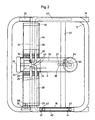
- the supporting structure which consists exclusively of inexpensive steel tubes, serves as the base frame for an entire model family, i.e. from the typist chair to the heavy executive chair.
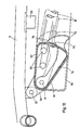
- the lower end of a support tube (3) which is bent at an obtuse angle, is slidably and rotatably guided on a support tube (2) which is firmly connected to a base (1) of the swivel chair, a plastic bushing (4) between the support tube (2) and the support tube (3). is provided for guidance and additional support.
- the standpipe (2) receives a gas pressure spring (6) on the inside in a plastic guide sleeve (5), which is supported at the bottom in the standpipe (2) on an axial pressure bearing (7) and with a cone (8) in a cone bushing (9 ) is seated, which is welded at (10) through a bore to the support tube (3) and at (11) with an insert tube (12) welded into the lower end of the support tube (3).
- a cross tube (13) is firmly connected to the upper end of the support tube (3).
- the support tube (3) and the cross tube (13) are cut out and welded together so that the clear cross section of both tubes (3, 13) is not constricted at any point by this connection.
- the cross tube (13) runs perpendicular to the support tube (3) and lies horizontally.
- a guide block (14) is fastened with screws (15) in the support tube (3).
- a locking bolt (16) is slidably mounted, which engages in a rack (19) for fixing an inclined position of a seat frame (17) and a backrest frame (18), which in the embodiment of FIGS. 1 and 2 is fastened to a crossbar (20) of the seat frame (17) and projects into the support tube (3) via an opening (21).
- the toothed rack (19) has a longer tooth (22) at the free inner end which, when the locking bolt (16) is withdrawn, abuts against it, so that the toothed rack (19) is not completely pulled out of the opening (21) of the support tube (3) can.
- the release movement of the locking bolt (16) is limited by a leaf spring (23) which can be pushed away with a screwdriver or the like when the mechanism is removed.
- the locking bolt (16) is connected via a connecting rod (24) to a lever (25) on a shaft (26) which is mounted in bearing blocks (27, 28) within the left side of the cross tube (13) and one at the outer end Actuating lever (not shown here) that is accessible at the front left under the seat frame (17).
- bearing blocks (27, 28) In the right side of the cross tube (13) there are further bearing blocks (29, 30) in which a further shaft (31) aligned with the shaft (26) is mounted, which shaft belongs to the actuating mechanism for the height adjustment of the chair.
- a lever (32) at the inner end of the shaft (31) is connected via a connecting rod (33) to an angle lever (34) which is mounted at the rear end of the guide block (14) and which is accessible under the seat when actuated at the front right Actuating lever (35) (Fig. 2) presses on a tappet (36) of the valve of the gas pressure spring (6) to release it for height adjustment.
- the seat frame (17) has bearing eyelets (37) on both sides at the front end, which are rotatably mounted on pins (38) that can be screwed into the outer bearing blocks (27, 29).
- the axis for the pivot mounting of the backrest frame (18) in the bearing blocks (27-30) is formed by two torsion springs (39), each of which is fixed with a long spring leg (40) in an associated tube of the lower part of the backrest frame (18) .
- bushings (41) are provided in these tubes, and the spring legs (40) have flats (42) on which clamping screws (not shown) engage.
- the torsion springs (39) have shorter spring legs (43) which press against a stop block (44) designed as an adjusting nut, which at the front end of the support tube (3) with a knurled disc (45) is adjustable to the spring force the torsion springs (39).
- the seat frame (17) and the backrest frame (18) are connected to one another on both sides by articulated brackets (46).
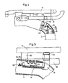
- the exemplary embodiment shown in FIG. 4 differs from the exemplary embodiment according to FIG. 1 only in that the toothed rack (19) is fastened here to a crossbar (49) of the lower part of the backrest frame (18) and the latter to the seat frame (17) is connected via a rubber-metal buffer (50).
- the torsion springs (39) are preferably made from round steel, but can also consist of leaf spring assemblies.
- the upholstery of the chair, not shown, can be arbitrary, since the chair frame described and its mechanics, as mentioned at the beginning, serve as the base frame for an entire model family.
- Fig. 5 shows in partial section a further embodiment of the swivel chair.
- the locking bolt (16 ⁇ ) is under the force of a spring (51), which strives to insert the locking bolt (16 ⁇ ) in the rack (19).
- a button (not shown here) for triggering the latch (16 ⁇ ) is designed as a latching button, ie when the button is pressed for the first time, the latch (16 ⁇ ) is pulled out of the rack (19) in order to be released again when the button is pressed a second time .
- a latching device with a pawl (54) which can be pivoted in two planes under the force of a spring (53) is used, as is customary with latching switch buttons of electrical or electronic devices and therefore in detail need not be described.
- the pawl (54) works with a pin (55) on the locking bolt (16 ⁇ ).
- the outermost ends of the torsion springs (39 ⁇ ) are positively connected to pipes (57) via coupling bushes (56) (see FIGS. 7 and 8), which transmit the torsional force in the direction of a spindle nut (44 ⁇ ).
- Flattened ends (58) of the torsion springs (39 ⁇ ) are in corresponding flat bores (59) of the coupling bushes (56).
- hooks (60) are attached, which engage in hook-shaped lugs (61) on the spindle nut (44 ⁇ ).
- the pretension of the torsion springs (39 ⁇ ) can be adjusted by adjusting an adjusting spindle (62) seated in the spindle nut (44 ⁇ ) by means of a rotary knob (63).
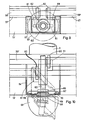
- the figures 9 to 11 show the adjustment mechanism for the prestressing of the torsion springs (39 ⁇ ) somewhat enlarged.
- a rectangular housing-like extension (64) protruding towards the front is attached to the cross tube (13 ⁇ ), in which the adjusting spindle (62) and the spindle nut (44 ⁇ ) are located.
- the adjusting spindle (62) has an annular collar (65) on which an axial ball bearing (66) rests, which finds its other abutment on a substantially rectangular counter-pressure disc (67), which, as indicated by dash-dotted lines in Fig. 10, the installation of the Spindle (62) with nut (44 ⁇ ) and their own installation without screws and tools allows because the counter pressure plate (67) has an enlarged bore (68).
- the counter pressure plate (67) sits in a recess (70) of the housing-like extension (64) in the assembled state.
- a race (72) for the ball bearing (66) is seated in a circular bead (71) of the recess (69) and has a bore adapted to the spindle (62) and therefore the adjusting spindle (62) localized concentrically to the enlarged bore (68) of the counter pressure plate (67), namely under the constant pressure of the torsion springs (39 ⁇ ).
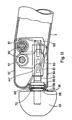
- Fig. 12 shows i.a. the arrangement and design of an actuation button (73), which is mounted at one end (here at the right end) of the cross tube (13 ⁇ ), via a lever (74) with the shaft (31) already mentioned in the description of FIG. 2 in Connection is established and belongs to the operating mechanism for the height adjustment of the swivel chair.
- the lever (74) protrudes through a slot (75) from the cross tube (13 ⁇ ), and the actuation button (73) has a beak-like extension (76) which covers the slot (75) in the rest position of the lever (74) and pinching injuries on fingers.
- the seat frame (17) can also be tilted to a limited extent about an axis (77) when this tilting movement is released by the latching bolt (16).
- the seat frame (17) is mounted on brackets (78) in front of the front upper edge of the cross tube (13 ⁇ ).
Landscapes
- Health & Medical Sciences (AREA)
- Dentistry (AREA)
- General Health & Medical Sciences (AREA)
- Chairs Characterized By Structure (AREA)
- Chair Legs, Seat Parts, And Backrests (AREA)
- Chairs For Special Purposes, Such As Reclining Chairs (AREA)
Claims (17)
a) le bras qui reçoit tout le mécanisme pour le déclenchement, le réglage et la fixation de l'inclinaison du châssis d'assise (17) et du châssis de dossier (18), pour le déclenchement du réglage en hauteur et pour le réglage de la force élastique de basculement, est un support tubulaire (3) coudé à angle obtus, dont l'extrémité inférieure entoure, avec possibilité de tourner et de coulisser, un montant tubulaire (2) monté sur un croisillon de piétement (1) et recevant le ressort pneumatique (6) et dont l'extrémité supérieure est reliée à une traverse tubulaire (13) s'étendant horizontalement transversalement au support tubulaire (3) et recevant à la fois les axes de basculement du châssis d'assise (17) et du châssis de dossier (18) ;
b) l'axe de basculement du châssis de dossier (18) est formé de deux ressorts de torsion (39), qui sont fixés chacun par une longue branche de ressort (40) coudée dans un tube de la partie inférieure du châssis de dossier (18) et qui s'appliquent par une courte branche de ressort (43) sur un plot de butée (44) déplaçable à l'extrémité supérieure du support tubulaire (3).
Priority Applications (1)
| Application Number | Priority Date | Filing Date | Title |
|---|---|---|---|
| AT87104799T ATE59761T1 (de) | 1986-05-15 | 1987-04-01 | Hoehenverstellbarer, mit gasdruckfeder ausgestatteter drehstuhl, insbesondere buerostuhl oder -sessel. |
Applications Claiming Priority (2)
| Application Number | Priority Date | Filing Date | Title |
|---|---|---|---|
| DE3616475A DE3616475C1 (de) | 1986-05-15 | 1986-05-15 | Hoehenverstellbarer,mit Gasdruckfeder ausgestatteter Drehstuhl,insbesondere Buerostuhl oder -sessel |
| DE3616475 | 1986-05-15 |
Publications (2)
| Publication Number | Publication Date |
|---|---|
| EP0247328A1 EP0247328A1 (fr) | 1987-12-02 |
| EP0247328B1 true EP0247328B1 (fr) | 1991-01-09 |
Family
ID=6300953
Family Applications (1)
| Application Number | Title | Priority Date | Filing Date |
|---|---|---|---|
| EP87104799A Expired - Lifetime EP0247328B1 (fr) | 1986-05-15 | 1987-04-01 | Chaise tournante et réglable en hauteur, comportant un ressort pneumatique, notamment chaise ou fauteuil de bureau |
Country Status (8)
| Country | Link |
|---|---|
| US (1) | US4779925A (fr) |
| EP (1) | EP0247328B1 (fr) |
| JP (1) | JP2505458B2 (fr) |
| AT (1) | ATE59761T1 (fr) |
| CA (1) | CA1276099C (fr) |
| DE (1) | DE3616475C1 (fr) |
| ES (1) | ES2020524B3 (fr) |
| NO (1) | NO871378L (fr) |
Families Citing this family (48)
| Publication number | Priority date | Publication date | Assignee | Title |
|---|---|---|---|---|
| DE3700447A1 (de) * | 1987-01-09 | 1988-07-21 | Vogt Bueromoebel | Sitzmoebel |
| US4840426A (en) * | 1987-09-30 | 1989-06-20 | Davis Furniture Industries, Inc. | Office chair |
| GB9107661D0 (en) * | 1991-04-11 | 1991-05-29 | Nat Res Dev | Adjustable chair |
| US5106157A (en) * | 1989-03-01 | 1992-04-21 | Herman Miller, Inc. | Chair height and tilt adjustment mechanisms |
| US5224758A (en) * | 1989-12-27 | 1993-07-06 | Itoki Crebio Corporation | Tilting control assembly for chair |
| NO174135C (no) * | 1990-09-05 | 1994-03-23 | Staal & Stil As | Arbeidsstol |
| JP2572828Y2 (ja) | 1992-04-01 | 1998-05-25 | 株式会社東洋工芸 | 椅子における座の昇降装置の操作構造 |
| CA2136967C (fr) | 1992-06-15 | 2001-04-03 | William E. Stumpf | Chaise de bureau |
| DE4331987A1 (de) * | 1993-09-21 | 1995-03-23 | Fredi Dubach | Stuhl, insbesondere Bürostuhl |
| WO1995034233A1 (fr) * | 1994-06-10 | 1995-12-21 | Haworth, Inc. | Fauteuil ergonomique |
| DE4436145A1 (de) * | 1994-10-11 | 1996-04-18 | Kusch Co Sitzmoebel | Sitzmöbel |
| US5634537A (en) * | 1995-04-19 | 1997-06-03 | Lord Corporation | Locking and positioning device |
| US5765914A (en) * | 1995-06-07 | 1998-06-16 | Herman Miller, Inc. | Chair with a tilt control mechanism |
| US5618021A (en) * | 1995-06-07 | 1997-04-08 | Sears Manufacturing Company | Seat suspension with ride zone protection apparatus |
| EP0804888B1 (fr) * | 1996-04-22 | 1997-11-19 | Steelcase Strafor (S.A.) | Perfectionnements aux systèmes de réglage et de commande des divers éléments mobiles et/ou déformables d'un siège de bureau |
| US5810439A (en) * | 1996-05-09 | 1998-09-22 | Haworth, Inc. | Forward-rearward tilt control for chair |
| US6079786A (en) * | 1997-05-07 | 2000-06-27 | Brunswick Corporation | One-shot pedestal swivel seat lock/release mechanism |
| US6022077A (en) * | 1997-05-07 | 2000-02-08 | Brunswick Corporation | One-shot pedestal swivel seat lock/release mechanism |
| US5918935A (en) * | 1997-06-03 | 1999-07-06 | Stulik; Edward L. | Reclining chair |
| US5871258A (en) | 1997-10-24 | 1999-02-16 | Steelcase Inc. | Chair with novel seat construction |
| US6250715B1 (en) | 1998-01-21 | 2001-06-26 | Herman Miller, Inc. | Chair |
| US6007150A (en) | 1998-03-08 | 1999-12-28 | Milsco Manufacturing Company | Motorcycle seat with adjustable backrest |
| US6224155B1 (en) | 1999-01-12 | 2001-05-01 | Steelcase Development Inc. | Vertical height adjustment mechanism for chairs |
| DE29910620U1 (de) * | 1999-06-17 | 2000-10-19 | König + Neurath AG, 61184 Karben | Stuhl, insbesondere Bürostuhl |
| DE10026292C2 (de) * | 1999-07-06 | 2003-03-20 | Roeder Peter | Stuhl |
| EP1175854A1 (fr) * | 2000-07-25 | 2002-01-30 | CO.FE.MO. S.p.A. | Dispositif de réglage pour chaise inclinable de bureau ou similaire |
| US6644741B2 (en) | 2001-09-20 | 2003-11-11 | Haworth, Inc. | Chair |
| US7625046B2 (en) | 2002-03-29 | 2009-12-01 | Garrex Llc | Task chair |
| US7396082B2 (en) * | 2002-03-29 | 2008-07-08 | Garrex Llc | Task chair |
| US7040703B2 (en) | 2002-03-29 | 2006-05-09 | Garrex Llc | Health chair a dynamically balanced task chair |
| US7396081B2 (en) * | 2003-05-16 | 2008-07-08 | Leggett & Platt Canada Co. | Chair height adjustment mechanism |
| US6942080B2 (en) * | 2003-12-04 | 2005-09-13 | Tsann Kuen Enterprise Co., Ltd. | Electrical appliance having a wire winding device |
| US6945602B2 (en) * | 2003-12-18 | 2005-09-20 | Haworth, Inc. | Tilt control mechanism for chair |
| US7237841B2 (en) | 2004-06-10 | 2007-07-03 | Steelcase Development Corporation | Back construction with flexible lumbar |
| US7458637B2 (en) | 2004-06-10 | 2008-12-02 | Steelcase Inc. | Back construction with flexible lumbar |
| US7922134B2 (en) * | 2004-10-19 | 2011-04-12 | Gasser Chair Company, Inc. | Objects including gaming stools with an easy rolling support base |
| CA2600310C (fr) * | 2005-03-01 | 2014-07-08 | Haworth, Inc. | Mecanisme de controle d'inclinaison d'un fauteuil |
| US7293832B2 (en) * | 2005-08-19 | 2007-11-13 | Chien-Kai Huang | Chair adjustable device |
| NO324513B1 (no) * | 2006-03-02 | 2007-11-05 | Jurek Buchacz | Vippefjaermekanisme for en stol, saerlig en kontor-eller arbeidsstol |
| BRPI0823267A2 (pt) | 2007-01-29 | 2013-09-24 | Miller Herman Inc | estrutura de assento e mÉtodos para uso da mesma |
| ITMI20070718A1 (it) * | 2007-04-06 | 2008-10-07 | L & P Property Management Co | Dispositivo di regolazione per sedie regolabili e simili. |
| DE202008014043U1 (de) * | 2008-10-22 | 2010-03-11 | Tepe-Walser, Silvia | Federweiche Lagerungszwischenstücke |
| DE102009010234A1 (de) * | 2009-02-24 | 2010-09-02 | Klöber GmbH | Synchronmechanik für Bürostühle mit einer Einstelleinrichtung für die Anpassung der Rückstellkraft an das Benutzergewicht |
| US9801471B2 (en) | 2014-04-17 | 2017-10-31 | Hni Technologies Inc. | Chair and chair control assemblies, systems, and methods |
| EP3927215B1 (fr) | 2019-02-21 | 2025-06-11 | Steelcase Inc. | Élément de soutien du corps |
| US11357329B2 (en) | 2019-12-13 | 2022-06-14 | Steelcase Inc. | Body support assembly and methods for the use and assembly thereof |
| WO2022197675A2 (fr) | 2021-03-17 | 2022-09-22 | Steelcase Inc. | Agencement de sièges |
| EP4464196A1 (fr) * | 2023-05-16 | 2024-11-20 | Vitra AG | Chaise et composition de meuble |
Family Cites Families (11)
| Publication number | Priority date | Publication date | Assignee | Title |
|---|---|---|---|---|
| US3136580A (en) * | 1962-05-22 | 1964-06-09 | Bassick Co | Chair control |
| CA806983A (en) * | 1965-07-23 | 1969-02-25 | Dufton Ronald | Chair tilting mechanism |
| US4373692A (en) * | 1980-05-01 | 1983-02-15 | Steelcase Inc. | Chair control with height adjustment actuator |
| DE3139448C2 (de) * | 1981-10-03 | 1984-06-07 | Kusch & Co Sitzmöbelwerke KG, 5789 Hallenberg | Stuhl |
| DE3303265C2 (de) * | 1983-02-01 | 1985-05-09 | Röder GmbH Sitzmöbelwerke, 6000 Frankfurt | Stuhl, insbesondere Bürostuhl |
| DE3316533A1 (de) * | 1983-05-06 | 1984-11-08 | Provenda Marketing AG, Herisau | Arbeitsstuhl, insbesondere buerostuhl |
| US4560199A (en) * | 1983-07-22 | 1985-12-24 | Pamont Ag | Recliner chair |
| DE3334424A1 (de) * | 1983-09-23 | 1985-04-11 | Girsberger AG, Bützberg | Bedienungsmechanismus fuer sitzmoebel |
| CA1184108A (fr) * | 1984-04-09 | 1985-03-19 | David W. Smith | Suspension de fauteuil basculant |
| DE8417429U1 (de) * | 1984-06-08 | 1984-09-20 | Hansen, Eckard, 9430 St. Margrethen | Punktsynchronverstelleinrichtung für Bürostühle |
| DE3509050A1 (de) * | 1984-10-24 | 1986-04-24 | Bürositzmöbelfabrik Friedrich-W. Dauphin GmbH & Co, 8561 Offenhausen | Betaetigungs-vorrichtung fuer den ausloesestoessel einer laengenverstellbaren gasfeder |
-
1986
- 1986-05-15 DE DE3616475A patent/DE3616475C1/de not_active Expired
-
1987
- 1987-04-01 EP EP87104799A patent/EP0247328B1/fr not_active Expired - Lifetime
- 1987-04-01 ES ES87104799T patent/ES2020524B3/es not_active Expired - Lifetime
- 1987-04-01 AT AT87104799T patent/ATE59761T1/de not_active IP Right Cessation
- 1987-04-02 NO NO871378A patent/NO871378L/no unknown
- 1987-04-22 US US07/045,878 patent/US4779925A/en not_active Expired - Fee Related
- 1987-05-06 JP JP62109066A patent/JP2505458B2/ja not_active Expired - Lifetime
- 1987-05-12 CA CA000536894A patent/CA1276099C/fr not_active Expired - Lifetime
Also Published As
| Publication number | Publication date |
|---|---|
| CA1276099C (fr) | 1990-11-13 |
| JP2505458B2 (ja) | 1996-06-12 |
| ATE59761T1 (de) | 1991-01-15 |
| DE3616475C1 (de) | 1987-06-11 |
| JPS6365818A (ja) | 1988-03-24 |
| NO871378D0 (no) | 1987-04-02 |
| ES2020524B3 (es) | 1991-08-16 |
| US4779925A (en) | 1988-10-25 |
| EP0247328A1 (fr) | 1987-12-02 |
| NO871378L (no) | 1987-11-16 |
Similar Documents
| Publication | Publication Date | Title |
|---|---|---|
| EP0247328B1 (fr) | Chaise tournante et réglable en hauteur, comportant un ressort pneumatique, notamment chaise ou fauteuil de bureau | |
| DE3741472C2 (fr) | ||
| EP0144577B1 (fr) | Dispositif de support pour un siège comportant un support de dossier et un siège, tous deux réglables en inclinaison | |
| EP0179185B1 (fr) | Chaise, notamment chaise de bureau | |
| EP0264029B1 (fr) | Chaise | |
| DE19945118B4 (de) | Sessel mit Aufstehhilfe | |
| DE1282880B (de) | Stuhl mit einer ausziehbaren Beinstuetze | |
| EP3120732B1 (fr) | Mecanisme de siege de bureau | |
| EP0397661B1 (fr) | Chaise, notamment chaise de travail ou de bureau | |
| EP3528664B1 (fr) | Dispositif de mécanisme synchrone et chaise en étant équipée | |
| DE69508618T2 (de) | Klappstuhl | |
| EP0233974B1 (fr) | Dispositif d'inclinaison pour sièges | |
| EP0931483B1 (fr) | Meuble d'assise ou de couchage | |
| DE1429413B2 (de) | Beschlag fuer einen in mehrere stellungen verstellbaren lehnstuhl | |
| DE69714910T2 (de) | Verstellvorrichtung | |
| EP0341344B1 (fr) | Meuble servant de siège | |
| BE1018255A3 (de) | Sitzmobel. | |
| DE1159147B (de) | Hebelsteuereinrichtung fuer die Beinstuetze eines Verstellsessels | |
| EP2477523B1 (fr) | Mécanisme de bascule pour une chaise de bureau | |
| DE1289630B (de) | Sitz-Liege-Verstellsessel | |
| EP0535262B1 (fr) | Chaise réglable et adaptable à la taille d'une personne, notamment chaise rotative | |
| WO2014183851A1 (fr) | Mécanique synchrone | |
| EP1074202B1 (fr) | Meuble pour s'asseoir | |
| CH663526A5 (en) | Chair | |
| DE20000613U1 (de) | Sitzmöbel |
Legal Events
| Date | Code | Title | Description |
|---|---|---|---|
| PUAI | Public reference made under article 153(3) epc to a published international application that has entered the european phase |
Free format text: ORIGINAL CODE: 0009012 |
|
| AK | Designated contracting states |
Kind code of ref document: A1 Designated state(s): AT BE CH ES FR GB GR IT LI NL SE |
|
| 17P | Request for examination filed |
Effective date: 19880525 |
|
| 17Q | First examination report despatched |
Effective date: 19890918 |
|
| GRAA | (expected) grant |
Free format text: ORIGINAL CODE: 0009210 |
|
| AK | Designated contracting states |
Kind code of ref document: B1 Designated state(s): AT BE CH ES FR GB GR IT LI NL SE |
|
| PG25 | Lapsed in a contracting state [announced via postgrant information from national office to epo] |
Ref country code: GR Free format text: LAPSE BECAUSE OF FAILURE TO SUBMIT A TRANSLATION OF THE DESCRIPTION OR TO PAY THE FEE WITHIN THE PRESCRIBED TIME-LIMIT Effective date: 19910109 |
|
| REF | Corresponds to: |
Ref document number: 59761 Country of ref document: AT Date of ref document: 19910115 Kind code of ref document: T |
|
| GBT | Gb: translation of ep patent filed (gb section 77(6)(a)/1977) | ||
| ET | Fr: translation filed | ||
| ITF | It: translation for a ep patent filed | ||
| PG25 | Lapsed in a contracting state [announced via postgrant information from national office to epo] |
Ref country code: AT Effective date: 19910401 |
|
| PGFP | Annual fee paid to national office [announced via postgrant information from national office to epo] |
Ref country code: SE Payment date: 19910403 Year of fee payment: 5 |
|
| PGFP | Annual fee paid to national office [announced via postgrant information from national office to epo] |
Ref country code: CH Payment date: 19910408 Year of fee payment: 5 |
|
| PGFP | Annual fee paid to national office [announced via postgrant information from national office to epo] |
Ref country code: NL Payment date: 19910430 Year of fee payment: 5 |
|
| PGFP | Annual fee paid to national office [announced via postgrant information from national office to epo] |
Ref country code: BE Payment date: 19910924 Year of fee payment: 5 |
|
| PLBE | No opposition filed within time limit |
Free format text: ORIGINAL CODE: 0009261 |
|
| STAA | Information on the status of an ep patent application or granted ep patent |
Free format text: STATUS: NO OPPOSITION FILED WITHIN TIME LIMIT |
|
| 26N | No opposition filed | ||
| PG25 | Lapsed in a contracting state [announced via postgrant information from national office to epo] |
Ref country code: SE Effective date: 19920402 |
|
| PG25 | Lapsed in a contracting state [announced via postgrant information from national office to epo] |
Ref country code: LI Effective date: 19920430 Ref country code: CH Effective date: 19920430 Ref country code: BE Effective date: 19920430 |
|
| BERE | Be: lapsed |
Owner name: KUSCH & CO. SITZMOBELWERKE K.G. Effective date: 19920430 |
|
| PG25 | Lapsed in a contracting state [announced via postgrant information from national office to epo] |
Ref country code: NL Effective date: 19921101 |
|
| NLV4 | Nl: lapsed or anulled due to non-payment of the annual fee | ||
| REG | Reference to a national code |
Ref country code: CH Ref legal event code: PL |
|
| PGFP | Annual fee paid to national office [announced via postgrant information from national office to epo] |
Ref country code: FR Payment date: 19930225 Year of fee payment: 7 |
|
| PGFP | Annual fee paid to national office [announced via postgrant information from national office to epo] |
Ref country code: ES Payment date: 19940209 Year of fee payment: 8 |
|
| PGFP | Annual fee paid to national office [announced via postgrant information from national office to epo] |
Ref country code: GB Payment date: 19940325 Year of fee payment: 8 |
|
| PG25 | Lapsed in a contracting state [announced via postgrant information from national office to epo] |
Ref country code: FR Effective date: 19941229 |
|
| EUG | Se: european patent has lapsed |
Ref document number: 87104799.9 Effective date: 19921108 |
|
| REG | Reference to a national code |
Ref country code: FR Ref legal event code: ST |
|
| PG25 | Lapsed in a contracting state [announced via postgrant information from national office to epo] |
Ref country code: GB Effective date: 19950401 |
|
| PG25 | Lapsed in a contracting state [announced via postgrant information from national office to epo] |
Ref country code: ES Free format text: LAPSE BECAUSE OF NON-PAYMENT OF DUE FEES Effective date: 19950403 |
|
| GBPC | Gb: european patent ceased through non-payment of renewal fee |
Effective date: 19950401 |
|
| REG | Reference to a national code |
Ref country code: ES Ref legal event code: FD2A Effective date: 19990201 |
|
| PG25 | Lapsed in a contracting state [announced via postgrant information from national office to epo] |
Ref country code: IT Free format text: LAPSE BECAUSE OF NON-PAYMENT OF DUE FEES;WARNING: LAPSES OF ITALIAN PATENTS WITH EFFECTIVE DATE BEFORE 2007 MAY HAVE OCCURRED AT ANY TIME BEFORE 2007. THE CORRECT EFFECTIVE DATE MAY BE DIFFERENT FROM THE ONE RECORDED. Effective date: 20050401 |