EP0535262B1 - Chaise réglable et adaptable à la taille d'une personne, notamment chaise rotative - Google Patents
Chaise réglable et adaptable à la taille d'une personne, notamment chaise rotative Download PDFInfo
- Publication number
- EP0535262B1 EP0535262B1 EP91116685A EP91116685A EP0535262B1 EP 0535262 B1 EP0535262 B1 EP 0535262B1 EP 91116685 A EP91116685 A EP 91116685A EP 91116685 A EP91116685 A EP 91116685A EP 0535262 B1 EP0535262 B1 EP 0535262B1
- Authority
- EP
- European Patent Office
- Prior art keywords
- seat
- backrest
- chair
- transverse axis
- support arms
- Prior art date
- Legal status (The legal status is an assumption and is not a legal conclusion. Google has not performed a legal analysis and makes no representation as to the accuracy of the status listed.)
- Expired - Lifetime
Links
Images


Classifications
-
- A—HUMAN NECESSITIES
- A47—FURNITURE; DOMESTIC ARTICLES OR APPLIANCES; COFFEE MILLS; SPICE MILLS; SUCTION CLEANERS IN GENERAL
- A47C—CHAIRS; SOFAS; BEDS
- A47C1/00—Chairs adapted for special purposes
- A47C1/02—Reclining or easy chairs
- A47C1/022—Reclining or easy chairs having independently-adjustable supporting parts
- A47C1/023—Reclining or easy chairs having independently-adjustable supporting parts the parts being horizontally-adjustable seats ; Expandable seats or the like, e.g. seats with horizontally adjustable parts
-
- A—HUMAN NECESSITIES
- A47—FURNITURE; DOMESTIC ARTICLES OR APPLIANCES; COFFEE MILLS; SPICE MILLS; SUCTION CLEANERS IN GENERAL
- A47C—CHAIRS; SOFAS; BEDS
- A47C1/00—Chairs adapted for special purposes
- A47C1/02—Reclining or easy chairs
- A47C1/031—Reclining or easy chairs having coupled concurrently adjustable supporting parts
- A47C1/032—Reclining or easy chairs having coupled concurrently adjustable supporting parts the parts being movably-coupled seat and back-rest
- A47C1/03261—Reclining or easy chairs having coupled concurrently adjustable supporting parts the parts being movably-coupled seat and back-rest characterised by elastic means
- A47C1/03272—Reclining or easy chairs having coupled concurrently adjustable supporting parts the parts being movably-coupled seat and back-rest characterised by elastic means with coil springs
-
- A—HUMAN NECESSITIES
- A47—FURNITURE; DOMESTIC ARTICLES OR APPLIANCES; COFFEE MILLS; SPICE MILLS; SUCTION CLEANERS IN GENERAL
- A47C—CHAIRS; SOFAS; BEDS
- A47C1/00—Chairs adapted for special purposes
- A47C1/02—Reclining or easy chairs
- A47C1/031—Reclining or easy chairs having coupled concurrently adjustable supporting parts
- A47C1/032—Reclining or easy chairs having coupled concurrently adjustable supporting parts the parts being movably-coupled seat and back-rest
- A47C1/03255—Reclining or easy chairs having coupled concurrently adjustable supporting parts the parts being movably-coupled seat and back-rest with a central column, e.g. rocking office chairs
-
- A—HUMAN NECESSITIES
- A47—FURNITURE; DOMESTIC ARTICLES OR APPLIANCES; COFFEE MILLS; SPICE MILLS; SUCTION CLEANERS IN GENERAL
- A47C—CHAIRS; SOFAS; BEDS
- A47C1/00—Chairs adapted for special purposes
- A47C1/02—Reclining or easy chairs
- A47C1/031—Reclining or easy chairs having coupled concurrently adjustable supporting parts
- A47C1/032—Reclining or easy chairs having coupled concurrently adjustable supporting parts the parts being movably-coupled seat and back-rest
- A47C1/03261—Reclining or easy chairs having coupled concurrently adjustable supporting parts the parts being movably-coupled seat and back-rest characterised by elastic means
- A47C1/03266—Reclining or easy chairs having coupled concurrently adjustable supporting parts the parts being movably-coupled seat and back-rest characterised by elastic means with adjustable elasticity
Definitions
- the invention relates to a multi-adjustable, adaptable to the size of the chair, in particular swivel chair, in which the seat back independent of the seat is held by two support arms that extend from a first transverse axis under the seat laterally from this to the rear and variable in length as in different lengths can be determined by a locking device.
- a chair of this type is known from DE 33 23 171 A1.
- the well-known chair already has an adjustable seat height.
- the support arms designed as a hollow tube, which form an angle of 30 ° with the horizontal here, mean that when the height of the backrest is raised above the seat, the seat depth increases at the same time.
- neither the backrest nor the seat can be tilted.
- Permanent mechanics and synchronous mechanisms are also known.
- the seat is rigidly connected to the chair base, i.e. cannot be tilted, while the backrest is attached to the chair base so that it can be tilted against the action of a spring.
- the backrest can thus be optimally matched to the back regardless of the seat. Since the rigid seat does not follow the movements of the backrest, there are also considerable disadvantages.
- the seat and backrest are coupled in such a way that when the backrest is returned, the seat is also tilted backwards.
- the seat weight portion already causes the backrest to tip backwards even in the front sitting position, so that it loses its supporting effect.
- a chair with synchronous mechanism (DE 38 17 761 C2) is also known, in which the backrest is held by two support arms running on both sides of the seat at approximately 40 ° to the rear, which are in their foremost region, i.e. under the front edge of the seat rigid seat supports are pivotally mounted. Between this pivot axis and the connection of the support arms to the backrest, a downwardly projecting mounting bracket is provided, on which the seat with its central region is rotatably mounted.
- the object of the invention is therefore to propose a chair with synchronous mechanism in which the seat depth, backrest height and armrest height can be adjusted at the same time and the synchronous mechanism in the front seat posture is automatically locked so that the seat force does not lead to a reduction in the support effect of the backrest on the back.
- the backrest is supported by two support arms which are mounted on the seat and extend laterally from this to the rear and are variable in length and which can be locked in different lengths by a locking device.
- This adjusts the seat depth and backrest height at the same time.
- the upper part of the telescopically subdivided, length-adjustable support arm is also provided with an armrest, then the armrest height is also adjusted at the same time.
- the seat depth, backrest height and armrest height can thus be adjusted synchronously with a single, sensible adjustment.
- a single chair construction can also be made accessible to an extremely wide range of user sizes, since there is a particularly large size change range.
- This size change range is decisively shaped by the fact that the support arms form an angle of at least 45 °, preferably over 50 ° and at least almost 52 ° with the horizontal in the rest position. Because in this way a height adjustment range of the upper support point of the iliac crest of 180 - 230 mm is achieved. At the same time, the armrest has a height adjustment range of 200 to 260 mm above the seating point and the seat depth can also be changed over a wide range. Given the steep position of the support arms, the optimal articulation point for their lower ends is at a distance of one third of the seat depth from the front edge of the seat.
- the seat is first mounted in the mechanical housing in the usual manner at its front end about a horizontal axis.
- the seat is also pushed up by a spring, just as another spring pushes the backrest forward.
- a rigid support is set between the mechanism housing and the seat at a distance from the pivot axis of the seat. This is designed so that it is only released when the backrest is clearly and deliberately deflected by the user to the rear, and then the synchronizing mechanism can take effect.
- the rigid support does not have any effect on the load on the seat by the user on the backrest. This does not swing back when the user sits down, nor is the force of the spring pushing the backrest forward reduced.
- the advantages of permanent mechanics and synchronous mechanics are actually combined in one chair with easy adjustment.
- the support arms are extended beyond their articulation under the seat and each carry a swivel plate, which itself, or preferably via another, on the one hand on the swivel plate and on the other hand on the transverse axis between the two levers the support articulated pull lever is connected to it and thereby dissolves or sets it up.
- this chair is also pushed upwards by a spring and the backrest is pushed forward.
- the spring pushing the seat upwards is inserted between the mechanical housing acting as the support and the seat, the point of application of this spring pushing the seat upwards being in the vicinity of the transverse axis arranged thirdly below the seat from its front edge.
- Mechanical springs are used as springs, which have the advantage of the progressive effect compared to the almost linear identification of a gas spring: with increasing deflection, the restoring force increases. This is particularly important for the restoring force on the backrest for ergonomic reasons.
- the seat is given an inclination of 3 to 4 ° forward in the rest position. This is the starting point for the synchronous kinematics after the support of the seat has been released, so that a pre-rotation of the pelvis is initiated to straighten the spine.
- the specified forward tilt is a compromise between this effect achieved and a limitation of the forward tilt to a value which prevents the user from sliding forward from the seat.
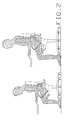
- FIG. 1 shows a chair with a chair base 10, to which a mechanical housing 12 is rigidly connected, which covers or supports all the parts explained below.
- a seat 14 is pivoted in the mechanical housing 12 at its front end about a transverse axis.
- a backrest 16 is not directly connected to the seat, but via telescopic support arms 18 with locking device 20 and armrests 22.
- the lower end of the support arms 18 is in each case on a horizontally and transversely extending first transverse axis 24 pivoted. This applies to the lower or inner part of the telescopic support arm.
- the upper or outer part of the telescopic support arms 18 connected to the backrest has the armrest. The user can release the rigid connection of the two parts of the support arms 18 against each other by actuating the locking device and the upper part of the support arms guided in the manner indicated in the figure on the lower part of the Pull the support arms up and fix them in the desired position.
- Fig. 3 shows the corresponding structure in detail.
- the mechanical housing 12 is fastened on the chair base 10 and holds the support arms 18 of the backrest (not shown in the figure) via the first transverse axis 24 and the seat 14 via a second transverse axis 26.
- the first transverse axis 24 is to be arranged at a third of the total seat depth and as high as possible, that is to say close to the seat 14.
- the second transverse axis 26 lies in the foremost region of the seat shell 12, that is to say at the front edge of the seat.
- the seat 14 is slightly inclined forward. For this purpose, it is pressed upwards by a spring, as will be explained in more detail below with reference to FIG. 4.
- the spring pivots the seat 14 about the second transverse axis 26 in the counterclockwise direction. This pivoting is limited by a rigid support from two levers connected in a third transverse axis 28.
- the somewhat longer lever 30 is articulated at its upper end on the underside of the seat 14 and approximately vertically above the axis of the chair base 10, specifically on a dimensionally stable seat support 34 integrated in the seat 14, the front end in the mechanical housing 12 is pivotally mounted on the second transverse axis 26.
- the figure also shows that the lower end of the somewhat shorter lever 32 is articulated somewhat next to and in front of the axis of the chair base 10.
- the lever 32 is also supported with a rear-facing nose on top of the chair foot on a cushion.
- the figure in particular clearly shows that the two levers 30, 32 are approximately aligned with one another, so that they form a rigid support for the seat 14 in the basic position shown in FIG. 3 (backrest in front), which is further supported by the nose of the lever 32 is. In this position, the rear end of the seat 14 cannot therefore descend downward due to the support. Rather, a rigid triangular combination of seat 14, support from levers 30, 32 and mechanical housing 12 is formed. As a result, the synchronous mechanism in the foremost position of the backrest 16 is rendered ineffective.
- Fig. 3 shows an embodiment in which the pivot plate 36 is connected to the pull lever 38 in a link 40 such that the connecting line of link 40 and attachment of the lower ends of the support arms 18 on the pivot plate on the support arms 18 is perpendicular.
- the pivot plate 36 further carries at its rear upper end in recesses 42 a cross bar 50 as the point of engagement of a compression spring 46 (see below) which presses the backrest 16 forward.
- the swivel plate has three transverse holes 44 at the front, with the aid of which, according to the wishes of the user, different backrest positions can be fixed by a pin guided in the mechanical housing.
- the pull lever 38 has the effect that when the user leans against the backrest 16, pushes it backwards and thus pivots the support arms 18 clockwise about the first transverse axis 24, the pivot plate 36 via the pull lever 38 on the third transverse axis 28 pulls, the angle between the levers 30, 32 is increasingly reduced and after the pivoting of the support arms 18 by a few degrees, the rigid support of the seat 14 on the mechanical housing 12 is released.
- the seat 14 is now released and can move through the synchronous mechanism coupled to the backrest with its rear section pivoting downward about the second transverse axis 26 when the backrest 16 is pivoted further backward.
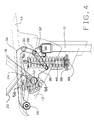
- Fig. 4 now shows, in addition, a compression spring 46 in the form of a mechanical coil spring, which is set axially parallel to the axis of the chair foot 10 in front of this in a corresponding receptacle 48 of the mechanism housing 12 and with its upper end on a cross bar 50 and via this on the swivel plate 36 and thus engages on the backrest 16 via the support arms 18, which is therefore pressed forward by the compression springs 46. If the user of the chair leans against the backrest 16, the compression spring designed as a mechanical coil spring is compressed accordingly between the crossbar 50 and its receptacle 48 and thus progressively increases its restoring force on the backrest in accordance with the spring constant.
- a compression spring 46 in the form of a mechanical coil spring, which is set axially parallel to the axis of the chair foot 10 in front of this in a corresponding receptacle 48 of the mechanism housing 12 and with its upper end on a cross bar 50 and via this on the swivel plate 36 and thus engages on
- a compression spring 52 in the form of a mechanical coil spring can be seen, which is inserted between a first linkage 54 on the mechanical housing 12, and a second linkage 56 on the seat support 34, which is in the region of the first transverse axis 24 on the underside of the Seat 14 is provided.
- the compression spring 52 thus serves to press the seat 14 upward about the second transverse axis 26, that is to say to pivot it counterclockwise in FIG. 4.
- the exemplary embodiments shown in FIG. 4 for the springs 46, 52 are only two examples of numerous possibilities for spring loading of the seat 14 and backrest 16 with which these are held in the basic position. It is also clear that the compression spring 46 not only brings the backrest into the foremost position, but at the same time also ensures that in this position the rigid support from the levers 30 and 32 is again set up when this by pivoting the backrest to the rear once resolved in the manner discussed above.
Claims (10)
- Chaise à réglages multiples, adaptable à la taille d'une personne, notamment chaise rotative, où le dossier (16) indépendant du siège (14) est tenu par deux bras de support (18) qui s'étendent en partant d'un premier axe transversal (24) sous le siège, latéralement à celui-ci vers l'arrière en haut et qui peuvent être fixés, en étant modifiables on longueur, ainsi que dans des longueurs différentes par un dispositif d'arrêt (20), caractérisée en ce que les bras de support (18) forment avec l'horizontale dans la position de repos un angle d'au moins 45°, de préférence supérieure à 50° et au moins approximativement de 52°, en ce que le premier axe transversal (24) comme axe de pivotement pour l'extrémité inférieure des bras de support est disposé dans un boîtier mécanique (12) réglable en hauteur devant le pied de la chaise (10) et à une distance d'un tiers de la profondeur d'assise relativement au bord de siège avant, en ce que le siège (14) est logé à son extrémité avant de façon pivotante autour d'un deuxième axe transversal (26) dans le boîtier mécanique (12) et est sollicité par un ressort (52) vers le haut, en ce que le dossier (16) est sollicité par un ressort (46) s'appliquant aux bras de support (18) vers l'avant, et en ce que l'accouplement synchrone du siège (14) et du dossier (16) dans la position la plus avant du dossier est supprimé par un support solide (30, 32) du siège (14) à la coque de siège (12).
- Chaise selon la revendication 1, caractérisée en ce que la partie reliée au dossier (16) des bras de support (18) dont la longueur est réglable télescopiquement porte également un accoudoir (22).
- Chaise selon la revendication 1, caractérisée en ce que les ressorts s'appliquant au dossier (16) et au siège (14) sont des ressorts mécaniques.
- Chaise selon la revendication 3, caractérisée en ce que le ressort (52) poussant le siège (14) vers le haut s'applique à celui-ci au voisinage du premier axe transversal (24).
- Chaise selon l'une des revendications 1 à 4, caractérisée en ce que le support rigide du siège (14) a lieu dans la position la plus avant du dossier (16) à la coque de siège (12) par deux leviers (30, 32) qui sont reliés dans un troisième axe transversal (28) auquel s'applique par ailleurs respectivement l'extrémité inférieure du bras de support (18).
- Chaise selon la revendication 5, caractérisée en ce que l'application de l'extrémité inférieure des bras de support (18) a lieu au troisième axe transversal par un levier de traction (38).
- Chaise selon l'une des revendications 1 à 6, caractérisée en ce que les parties inférieures des bras de support (18) portent respectivement une plaque pivotante (36) qui est fixée à un prolongement des bras de support en faisant saillie sur le premier axe transversal (24).
- Chaise selon la revendication 6 ou 7, caractérisée en ce que la plaque de pivotement (36) à peu près triangulaire présente à son extrémité inférieure arrière une articulation (40) pour le levier de traction (38) et à son extrémité supérieure arrière un évidement (42) pour une tige transversale (50) à laquelle s'applique un ressort de compression (46) sollicitant le dossier qui est réglé pour être au moins presque paraxial au pied de chaise (10) dans le boîtier mécanique (12).
- Chaise selon l'une des revendications 6 à 8, caractérisée en ce que le levier supérieur parmi les deux leviers de support (30) s'applique au siège (14) au moins à peu près dans le prolongement de l'axe du pied de chaise (10).
- Chaise selon l'une des revendications 1 à 9, caractérisée en ce que le siège (14), dans sa position supportée rigidement, est incliné par rapport à l'horizontale de 3 à 4 degrés vers l'avant.
Priority Applications (4)
| Application Number | Priority Date | Filing Date | Title |
|---|---|---|---|
| ES91116685T ES2080211T3 (es) | 1991-09-30 | 1991-09-30 | Silla adaptable a la estatura, de graduacion multiple, especialmente silla giratoria. |
| DE59107042T DE59107042D1 (de) | 1991-09-30 | 1991-09-30 | Mehrfach verstellbarer, an die Körpergrösse anpassbarer Stuhl, insbesondere Drehstuhl. |
| EP91116685A EP0535262B1 (fr) | 1991-09-30 | 1991-09-30 | Chaise réglable et adaptable à la taille d'une personne, notamment chaise rotative |
| AT91116685T ATE131016T1 (de) | 1991-09-30 | 1991-09-30 | Mehrfach verstellbarer, an die körpergrösse anpassbarer stuhl, insbesondere drehstuhl. |
Applications Claiming Priority (1)
| Application Number | Priority Date | Filing Date | Title |
|---|---|---|---|
| EP91116685A EP0535262B1 (fr) | 1991-09-30 | 1991-09-30 | Chaise réglable et adaptable à la taille d'une personne, notamment chaise rotative |
Publications (2)
| Publication Number | Publication Date |
|---|---|
| EP0535262A1 EP0535262A1 (fr) | 1993-04-07 |
| EP0535262B1 true EP0535262B1 (fr) | 1995-12-06 |
Family
ID=8207225
Family Applications (1)
| Application Number | Title | Priority Date | Filing Date |
|---|---|---|---|
| EP91116685A Expired - Lifetime EP0535262B1 (fr) | 1991-09-30 | 1991-09-30 | Chaise réglable et adaptable à la taille d'une personne, notamment chaise rotative |
Country Status (4)
| Country | Link |
|---|---|
| EP (1) | EP0535262B1 (fr) |
| AT (1) | ATE131016T1 (fr) |
| DE (1) | DE59107042D1 (fr) |
| ES (1) | ES2080211T3 (fr) |
Families Citing this family (2)
| Publication number | Priority date | Publication date | Assignee | Title |
|---|---|---|---|---|
| US20040189073A1 (en) * | 2003-03-28 | 2004-09-30 | Donald Chadwick | Adjustable chair |
| US10485346B2 (en) * | 2018-01-22 | 2019-11-26 | Knoll, Inc. | Chair tilt mechanism |
Family Cites Families (5)
| Publication number | Priority date | Publication date | Assignee | Title |
|---|---|---|---|---|
| DE1239451B (de) * | 1962-05-29 | 1967-04-27 | Dr Dr Hans W Juergens | Stuhl mit in der Hoehe verstellbarem Sitz und mit verstellbarer Lehne |
| US3215470A (en) * | 1964-05-22 | 1965-11-02 | Milsco Mfg Co | Seat with adjustable elements |
| DE1808395B2 (fr) * | 1968-11-12 | 1970-09-03 | ||
| DE8607194U1 (de) * | 1986-03-15 | 1986-04-30 | Drabert Söhne Minden (Westf.), 4950 Minden | Sitzmöbel |
| DE3838999A1 (de) * | 1988-11-18 | 1990-05-23 | Roeder Gmbh | Stuhl, insbesondere arbeits- oder buerostuhl |
-
1991
- 1991-09-30 ES ES91116685T patent/ES2080211T3/es not_active Expired - Lifetime
- 1991-09-30 EP EP91116685A patent/EP0535262B1/fr not_active Expired - Lifetime
- 1991-09-30 AT AT91116685T patent/ATE131016T1/de not_active IP Right Cessation
- 1991-09-30 DE DE59107042T patent/DE59107042D1/de not_active Expired - Fee Related
Also Published As
| Publication number | Publication date |
|---|---|
| ES2080211T3 (es) | 1996-02-01 |
| ATE131016T1 (de) | 1995-12-15 |
| DE59107042D1 (de) | 1996-01-18 |
| EP0535262A1 (fr) | 1993-04-07 |
Similar Documents
| Publication | Publication Date | Title |
|---|---|---|
| DE102012107778B4 (de) | Stuhl, insbesondere Bürostuhl | |
| EP0247311B1 (fr) | Chaise | |
| EP2374371B1 (fr) | Meuble destiné à s'assoir doté d'un siège basculant dans une position d'aide à la montée en position debout | |
| AT402602B (de) | Stuhl stuhl | |
| EP2051606B1 (fr) | Fauteuil | |
| EP1358821B1 (fr) | Chaise avec un accumulateur d'energie dépendant du poids d'utilisateur | |
| DE19830418B4 (de) | Stuhlanordnung | |
| EP2888975B1 (fr) | Siège de travail à mécanisme synchrone et ressort spiral | |
| EP1769704B1 (fr) | Meuble d'assise et/ou de couchage | |
| WO2007000270A1 (fr) | Mecanisme de synchronisation | |
| EP2070444B1 (fr) | Siège de bureau | |
| EP2070446A1 (fr) | Siège de bureau doté d'un dossier inclinable et de moyens destinés à limiter l'inclinaison du dossier | |
| EP0233974B1 (fr) | Dispositif d'inclinaison pour sièges | |
| EP2670279B1 (fr) | Mécanique synchrone | |
| DE2601691C3 (de) | Hebelverstellgetriebe für Sitz-Liegesessel | |
| EP0535262B1 (fr) | Chaise réglable et adaptable à la taille d'une personne, notamment chaise rotative | |
| DE202014101592U1 (de) | Stuhl | |
| DE102004012850B4 (de) | Rückenlehne für eine Sitzvorrichtung, insbesondere für einen Drehstuhl | |
| EP2111138B1 (fr) | Meuble d'assise avec un element pour pieds pivotant | |
| DE202014011308U1 (de) | Sitzmöbel | |
| EP2994017A1 (fr) | Mécanique synchrone | |
| WO2012041448A1 (fr) | Mécanisme synchronisé | |
| DE19700617C2 (de) | Sessel | |
| EP1074202B1 (fr) | Meuble pour s'asseoir | |
| DE2159642A1 (de) | Krankenstuhl |
Legal Events
| Date | Code | Title | Description |
|---|---|---|---|
| PUAI | Public reference made under article 153(3) epc to a published international application that has entered the european phase |
Free format text: ORIGINAL CODE: 0009012 |
|
| AK | Designated contracting states |
Kind code of ref document: A1 Designated state(s): AT BE CH DE DK ES FR GB LI NL SE |
|
| 17P | Request for examination filed |
Effective date: 19930811 |
|
| 17Q | First examination report despatched |
Effective date: 19950410 |
|
| GRAA | (expected) grant |
Free format text: ORIGINAL CODE: 0009210 |
|
| AK | Designated contracting states |
Kind code of ref document: B1 Designated state(s): AT BE CH DE DK ES FR GB LI NL SE |
|
| PG25 | Lapsed in a contracting state [announced via postgrant information from national office to epo] |
Ref country code: DK Effective date: 19951206 |
|
| REF | Corresponds to: |
Ref document number: 131016 Country of ref document: AT Date of ref document: 19951215 Kind code of ref document: T |
|
| REF | Corresponds to: |
Ref document number: 59107042 Country of ref document: DE Date of ref document: 19960118 |
|
| REG | Reference to a national code |
Ref country code: ES Ref legal event code: FG2A Ref document number: 2080211 Country of ref document: ES Kind code of ref document: T3 |
|
| GBT | Gb: translation of ep patent filed (gb section 77(6)(a)/1977) |
Effective date: 19960116 |
|
| REG | Reference to a national code |
Ref country code: CH Ref legal event code: NV Representative=s name: PATENTANWALTSBUERO JEAN HUNZIKER |
|
| PG25 | Lapsed in a contracting state [announced via postgrant information from national office to epo] |
Ref country code: SE Effective date: 19960306 |
|
| ET | Fr: translation filed | ||
| PG25 | Lapsed in a contracting state [announced via postgrant information from national office to epo] |
Ref country code: BE Effective date: 19960930 Ref country code: LI Effective date: 19960930 Ref country code: GB Effective date: 19960930 Ref country code: CH Effective date: 19960930 |
|
| PG25 | Lapsed in a contracting state [announced via postgrant information from national office to epo] |
Ref country code: ES Free format text: LAPSE BECAUSE OF NON-PAYMENT OF DUE FEES Effective date: 19961001 |
|
| PLBE | No opposition filed within time limit |
Free format text: ORIGINAL CODE: 0009261 |
|
| STAA | Information on the status of an ep patent application or granted ep patent |
Free format text: STATUS: NO OPPOSITION FILED WITHIN TIME LIMIT |
|
| 26N | No opposition filed | ||
| BERE | Be: lapsed |
Owner name: WIESNER-HAGER MOBEL G.M.B.H. Effective date: 19960930 |
|
| PG25 | Lapsed in a contracting state [announced via postgrant information from national office to epo] |
Ref country code: NL Effective date: 19970401 |
|
| REG | Reference to a national code |
Ref country code: CH Ref legal event code: PL |
|
| GBPC | Gb: european patent ceased through non-payment of renewal fee |
Effective date: 19960930 |
|
| NLV4 | Nl: lapsed or anulled due to non-payment of the annual fee |
Effective date: 19970401 |
|
| PG25 | Lapsed in a contracting state [announced via postgrant information from national office to epo] |
Ref country code: FR Effective date: 19970630 |
|
| REG | Reference to a national code |
Ref country code: FR Ref legal event code: ST |
|
| REG | Reference to a national code |
Ref country code: FR Ref legal event code: ST |
|
| REG | Reference to a national code |
Ref country code: ES Ref legal event code: FD2A Effective date: 19971011 |
|
| PGFP | Annual fee paid to national office [announced via postgrant information from national office to epo] |
Ref country code: AT Payment date: 20080903 Year of fee payment: 18 |
|
| PGFP | Annual fee paid to national office [announced via postgrant information from national office to epo] |
Ref country code: DE Payment date: 20080905 Year of fee payment: 18 |
|
| PG25 | Lapsed in a contracting state [announced via postgrant information from national office to epo] |
Ref country code: AT Free format text: LAPSE BECAUSE OF NON-PAYMENT OF DUE FEES Effective date: 20090930 |
|
| PG25 | Lapsed in a contracting state [announced via postgrant information from national office to epo] |
Ref country code: DE Free format text: LAPSE BECAUSE OF NON-PAYMENT OF DUE FEES Effective date: 20100401 |