EP2888975B1 - Siège de travail à mécanisme synchrone et ressort spiral - Google Patents
Siège de travail à mécanisme synchrone et ressort spiral Download PDFInfo
- Publication number
- EP2888975B1 EP2888975B1 EP14004054.4A EP14004054A EP2888975B1 EP 2888975 B1 EP2888975 B1 EP 2888975B1 EP 14004054 A EP14004054 A EP 14004054A EP 2888975 B1 EP2888975 B1 EP 2888975B1
- Authority
- EP
- European Patent Office
- Prior art keywords
- backrest
- spring
- seat
- rotation
- axis
- Prior art date
- Legal status (The legal status is an assumption and is not a legal conclusion. Google has not performed a legal analysis and makes no representation as to the accuracy of the status listed.)
- Active
Links
Images


Classifications
-
- A—HUMAN NECESSITIES
- A47—FURNITURE; DOMESTIC ARTICLES OR APPLIANCES; COFFEE MILLS; SPICE MILLS; SUCTION CLEANERS IN GENERAL
- A47C—CHAIRS; SOFAS; BEDS
- A47C1/00—Chairs adapted for special purposes
- A47C1/02—Reclining or easy chairs
- A47C1/031—Reclining or easy chairs having coupled concurrently adjustable supporting parts
- A47C1/032—Reclining or easy chairs having coupled concurrently adjustable supporting parts the parts being movably-coupled seat and back-rest
- A47C1/03261—Reclining or easy chairs having coupled concurrently adjustable supporting parts the parts being movably-coupled seat and back-rest characterised by elastic means
- A47C1/03277—Reclining or easy chairs having coupled concurrently adjustable supporting parts the parts being movably-coupled seat and back-rest characterised by elastic means with bar or leaf springs
-
- A—HUMAN NECESSITIES
- A47—FURNITURE; DOMESTIC ARTICLES OR APPLIANCES; COFFEE MILLS; SPICE MILLS; SUCTION CLEANERS IN GENERAL
- A47C—CHAIRS; SOFAS; BEDS
- A47C1/00—Chairs adapted for special purposes
- A47C1/02—Reclining or easy chairs
- A47C1/031—Reclining or easy chairs having coupled concurrently adjustable supporting parts
- A47C1/032—Reclining or easy chairs having coupled concurrently adjustable supporting parts the parts being movably-coupled seat and back-rest
- A47C1/03255—Reclining or easy chairs having coupled concurrently adjustable supporting parts the parts being movably-coupled seat and back-rest with a central column, e.g. rocking office chairs
Definitions
- a work chair with synchronous mechanism and bending spring is, for example, with the subject of CA 2 645 964 A1 ( WO 2007/110729 A2 ) known.
- the bending spring is formed by a backrest composed of two struts, wherein the front part of the backrest is the part to which the back of the user applies, while the rear part of the backrest as a separate, flexible spring bar or as a bending spring is connected to an associated synchronizing mechanism in the region of the seat support.
- the backrest is thus formed relatively spacious and has a relatively undesirably large thickness in the backrest area.
- a synchronous mechanism is characterized in that the swivel bar of the backrest is moved backwards into a specific smaller swivel angle of the seat carrier back to avoid the so-called shirt pushing effect.
- the handlebars used are only passive, so that no translation of an angular ratio of the inclination of the backrest takes place on the seat support. Rather, the inclination of the backrest takes the seat support at the same angle, which just does not prevent a shirt pushing effect.
- the DE 35 30 868 A1 is regarded as the closest prior art and discloses a work chair with synchronous mechanism, which transmits a backrest angle at a reduced angle to a seat pan pivotally mounted on a seat support.
- At least one spiral spring is connected to a first spring end with the backrest, the second spring end engages a rear, second axis of rotation on the seat carrier, wherein the bending spring is approximately plate-shaped and is connected at its upper end to the spring center of the longitudinal axis of the backrest with this.
- the DE 297 04 906 U1 and JP H07 184741 A disclose office chairs with backrests coupled to the seat by a pivoting mechanism and spring members.
- the invention is based on the object, a work chair with synchronous mechanism and bending spring of the type mentioned so further develop that with a smaller thickness of the backrest, a reliable realization of a synchronous mechanism with as few components is realized.
- the invention is characterized by the technical teaching of claim 1.
- the bending spring is approximately plate-shaped and connected with its upper end of the spring centrally to the longitudinal center axis of the backrest with this.
- the shape of the backrest is used to adapt to a plate-shaped bending spring, so that in a small space, a high spring force can be generated because the arranged in the central longitudinal region of the backrest bending spring is connected to this form-fitting. This avoids bending springs projecting from the plane of the backrest, as is known in the prior art.
- the hineingeMailde in the seat support side of the backrest is pivotally received in a first axis of rotation in the seat support at a distance from the first axis of rotation in the seat support - in the seat support - a second axis of rotation is arranged, in which the lower bendable part of the spiral spring is added, which bending spring with its other spring end is secured in the region of the backrest.
- the engaging in the seat support side of the backrest is pivotally received in a first axis of rotation in the seat support, and connected via a connected to the backrest, rear link in a third axis of rotation on the seat shell and that in Distance from the first axis of rotation in the seat carrier, the second axis of rotation is arranged, in which the lower bendable spring end of the spiral spring is added,
- the spiral spring can be plate-shaped and therefore can be mounted approximately in the center or in the backrest. This results in higher spring force a more favorable mounting position, compared with two bending springs according to the prior art, which are arranged only at the edge of the backrest.
- the Sp Schwarzweg that performs the spiral spring at a maximum pivoting of the backrest is about 30 mm.
- the invention is not limited thereto. Any spread paths may be used, the said dimension relating only to the proper fulfillment of the functions of a synchronous mechanism.
- An important feature of the invention is therefore that on or in the backrest a plate-shaped bending spring is integrated, which is fastened with its upper spring end to the backrest and attaches with its lower, resilient end to a second axis of rotation, via the seat support with the first axis of rotation is connected, wherein the first axis of rotation is connected to the backrest.
- the bending spring consists of a multi-layered and glued wood part, which consists of a highly resilient wood material, such. B. hickory or ash or other highly resilient material.
- the invention is not limited thereto.
- the bending spring may also be formed as a simply formed plate-shaped metal plate having the corresponding spring properties, or it may also be formed as a multi-layered metal bending plate.
- composites are possible, such as. B. the combination of plate-shaped spring elements in conjunction with layer-wise connected wood or plastic slats.
- the spiral spring can either be a simple part or as a layered part of carbon plate parts or carbon fiber parts.
- the thickness of the backrest can be significantly reduced compared to the prior art, because according to the invention the plate-shaped bending spring is arranged on the inside of the backrest in the surface of the backrest itself or on the outside of the backrest.
- high spring forces can be generated with small dimensions of the spiral spring.
- Another essential feature of the invention is that now with the spiral spring and the functions of a synchronous mechanism can be met in perfect manner.
- a third axis of rotation is arranged in the region of the seat shell, which forms a distance to both the first and the second axis of rotation.
- the backrest is received in two different axes of rotation, namely once in the first axis of rotation and secondly above the handlebar 8, which is fixedly connected to the backrest, with the third axis of rotation.
- a fourth axis of rotation At a distance from the seat shell-side third axis of rotation is a fourth axis of rotation in the region of the seat, in the front seat near area arranged. It follows that the fourth axis of rotation has a fixed distance from the third axis of rotation, because these two axes of rotation are accommodated in the seat shell itself.
- the fourth axis of rotation which is arranged at the front, seat-near region of the seat, the one, front end of a handlebar is received, the rear end is received in a fifth axis of rotation, which fifth axis of rotation is in turn arranged in the region of the seat support 2.
- the backrest In a spring-loaded bending against the spring force of the spiral spring, the backrest therefore pivots against the force of this bending spring to the rear and the firmly connected to the backrest handlebars, the seat is raised in an area on which lies about the center of gravity of the user.
- this third axis of rotation is moved backwards.
- the dreaded iliac crest loss is avoided because the buttocks position of the user on the seat 10 is tracked when pivoting the backrest back and therefore the user's iliac crest always rests in the same way on the backrest and does not lose this contact.
- the dreaded Shirtschiebe bin is avoided by the synchronous mechanism according to the invention using a spiral spring, because the middle handlebar not only raises the seat backwards, but also upwards, whereby there is no relative displacement of the user to the backrest.
- the body center of gravity is positioned exactly opposite the central link and the third axis of rotation of the seat and this third axis of rotation in the seat shell forms an offset in the horizontal direction to the arranged below the first axis of rotation in the seat support, whereby the two axes of rotation (third and first axis of rotation) are offset from each other and what in one of the backrest force of User counteracting moment is caused, which is caused by the body weight of the user.
- Another advantage of the invention is that the second axis of rotation, which is accommodated in the seat, remains stationary and the seat does not tilt downwards with an inclination of the backrest, but only is raised and moved, but avoided the downward effect becomes.
- This is a technical advantage because the weight of the upper body must be raised when erecting, not against gravity.
- a spiral spring very high spring forces can be generated in a small space.
- the use of such a spiral spring eliminates helical compression springs, which are usually arranged in pairs and the relatively short travel a high To produce spring force. Accordingly, the space required for helical compression springs is much greater than a bending spring, which is integrated in or on the backrest area.
- the user Due to the self-weight of the user, who preferably sits with his center of gravity above the seat shell side arranged third axis of rotation, the user feels balanced. It feels like a scale, because according to the shift of the user's center of gravity, the uniform back pressure for the user is always generated on the backrest.
- the illustrated embodiments show a work chair.
- the invention is not limited to the training as a work chair.
- the specified mechanism in conjunction with a spiral spring can also be used in conference chairs, side chairs and the like.
- the upper end of the lift column 1 is rotatably received in a recess in the region of the seat support 2.
- a first axis of rotation 3 is arranged, in which the free pivotable end of the lower part of the backrest 14 is received.
- the free lower end of the backrest 14 is connected via a flange 43 with a link 8, which link is pivotally received in the first axis of rotation 3.
- the invention is not limited to the arrangement of a plate-shaped bending spring 13 on the inside of the backrest 14.
- FIG. 5 shows the FIG. 5 in that such a bending spring 13 can itself also be formed from the material of the backrest 14 and can be released only by free cuts 41, which extend parallel to one another in the longitudinal direction, and however performs the same function, as described below with reference to the bending spring 13 according to FIGS FIGS. 1 to 4 is described.
- the invention is not limited to that the upper end of the bending spring 13 is fixed with a screw 16 to the backrest. Any other type of attachment can be used.
- the attachment of the bending spring 13 and the bending spring itself is covered by a cushion support 17 in the direction of the back of the user, wherein the cushion support 17 is covered with a backrest cushion 18.
- the bending spring 13 forms a bending section 35 (see FIG. 2 . 3 ), so that the lower, bendable end of the spiral spring is connected in the illustrated embodiment via a screw 12 with a bearing block 11.
- bearing block 11 is omitted and the lower free and bendable end (later also referred to as spring tabs 45) received directly in a second axis of rotation 6 is, which is arranged in the seat support 2 and is formed obliquely offset from the first axis of rotation 3.
- Both axes of rotation 3, 6 are thus fixedly arranged in the seat carrier 2.
- the seat 10 stops behind the axis of rotation 6 and has no connection to the axis of rotation 6, because this is arranged in the seat carrier 2.
- a fifth axis of rotation 4 is further arranged away from the first axis of rotation 3, which is arranged approximately in the lower, seat-near region of the seat support 2.
- This axis of rotation 4 receives a front link 7, the other, opposite end is arranged in a fourth axis of rotation 5, which is firmly received in the seat 10.
- the backrest pad 18 is detachably arranged on the cushion support 17 with the connection clips 19 on the inside of the backrest 14.
- the design of the seat shell 10 is selected such that the center of gravity of the user is offset by about a small distance 33 to the rear over the third axis of rotation 9 in the region of the seat shell 10.
- the handlebar 7 performs a pivoting movement in the fifth axis of rotation 4 in the direction of arrow 26.
- the handlebar 7 is inclined in accordance with the indicated angle 29 more towards the horizontal than comparatively the longitudinal axis by the handlebar 8, which forms a larger angle 30 to the horizontal.
- a vertical axis through the third axis of rotation 9, which is arranged on the seat 10 is designated 32.
- FIG. 2 shows the front lowered position compared to the in FIG. 1 illustrated neutral position is characterized in that the entire seat 10 in the direction of arrow 39 down from the neutral position 38 according to FIG. 1 emotional. This is in FIG. 2 located.
- the front lowered position is taken when the user's center of gravity is moved to the position 31 'forward and this occupies a greater distance 33' to the vertical axis 32.
- the seat 10 also moves slightly forward, because this corresponds to the return pivotal movement of the backrest 14.
- FIG. 3 shows the opposite position to FIG. 2 namely, the position of the backrest 14, which is leaning back strongly, and the seat shell 10 coupled thereto.
- the center of gravity 31 "shifts rearward by the distance 33" away from the vertical axis 32, thereby maximizing the spring force from the flexure 35 of the flexural spring.
- the bending spring is thus transmitted its maximum spring force on the bearing block 11 on the axis of rotation 6 and at the same time so as to spread from the lower part of the backrest 14.
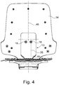
- FIG. 4 shows in a preferred embodiment, that the plate-shaped bending spring is formed as a one-piece bent part, which is arranged symmetrically in the region of the longitudinal center axis 46 of the backrest.
- the spring tab 45 forms a single, einscherin Westerniges part with the other parts of the bending spring 13 and is the lower end of the spring spring.
- the bending spring is formed as a multi-layered wood layer part.
- constriction 44 can be omitted, and the bending spring 13 can with their in FIG. 4 extend shown maximum width in the seat carrier area inside.
- two mutually parallel bending springs are arranged separately from each other via associated screw 16 on the inside of the backrest 14.
- FIG. 5 shows an opposite to the comments FIG. 1 and 4 modified embodiment in which the bending spring 13 is formed directly from the material of the backrest 14 by the arrangement of cutouts 41.
- the free cuts 41 have a length such that they extend approximately to half the height of the height of the backrest so as to allow a long bendable region of the bending spring 13.
- the invention is not limited to that according to the embodiment of FIGS. 1 to 4 the bending spring 13 an inside of the backrest 14 is attached.
- the plate-shaped bending spring 13 in the FIGS. 1 to 4 is attached to the outside of the backrest 14 and engages by a corresponding exemption on the lower rear side of the backrest in the seat support area.
- the bending spring in the backrest region is designed as a freestanding spring part, so that the attachment between the spiral spring and the backrest, which is designed as a screw 16 in the embodiment shown, is eliminated.
- this screw 16 would then be a plug connection, so that the backrest with a lower receiving part on the upper part of the bending spring can be plugged, the remaining lower part of the backrest, starting from the screw 16 in the direction of the connecting piece 15 is maintained and thus the backrest is divided into two parts. It therefore consists of an upper attachable to the bending spring part and a lower part, which extends starting from the connecting piece 15 approximately to the (attributable) screw 16.
Claims (9)
- Siège de travail à mécanisme synchrone qui transmet une inclinaison du dossier suivant un angle réduit (39, 40) à une assise (10) disposée pivotante sur un support d'assise (2), et au moins un ressort de flexion (13) est relié, à une extrémité de ressort, au dossier (14) tandis que sa seconde extrémité agit au niveau d'un deuxième axe de rotation, arrière (6) sur le support d'assise (2), le ressort de flexion ayant à peu près la forme d'une plaque et étant relié avec son extrémité supérieure au dossier (14), de manière centrée par rapport à l'axe longitudinal médian (46) de celui-ci, caractérisé en ce que le côté du dossier (14) qui pénètre dans le support d'assise (2) est logé pivotant dans un premier axe de rotation (3) dans le support d'assise (2) et agit par l'intermédiaire d'un bras de suspension arrière (8) relié au dossier (14) dans un troisième axe de rotation (9) sur l'assise (10), et en ce qu'à une certaine distance du premier axe de rotation (3) dans le support d'assise (2) est disposé le deuxième axe de rotation (6) dans lequel est logée l'extrémité de ressort flexible inférieure du ressort de flexion (13).
- Siège de travail selon la revendication 1, caractérisé en ce que le ressort de flexion (13) est disposé sur le dossier (14) sur le côté intérieur de celui-ci ou sur son côté extérieur, ou est intégré dans le dossier (14).
- Siège de travail selon l'une des revendications 1 ou 2, caractérisé en ce qu'il est prévu dans la zone de l'assise (10) un troisième axe de rotation (9) dans lequel est logée une extrémité pivotante d'un bras (8) dont l'autre extrémité est reliée de manière fixe à l'extrémié inférieure du dossier (14).
- Siège de travail selon l'une des revendications 1 à à 3, caractérisé en ce que l'extrémité flexible du ressort de flexion (13) agit sur un support du type à bras (11) qui est disposé avec son extrémité dans le deuxième axe de rotation (6) dans le support d'assise (2).
- Siège de travail selon l'une des revendications 1 à 4, caractérisé en ce qu'il est prévu dans la zone avant de l'assise (10) proche du siège, à une certaine distance du troisième axe de rotation (9) sur ladite assise (10), un quatrième axe de rotation (5) pour la liaison avec un bras (7) dont l'autre extrémité est logée pivotante dans un cinquième axe de rotation (4) sur la partie avant du support d'assise (2).
- Siège de travail selon l'une des revendications 1 à 5, caractérisé en ce que le centre de gravité du corps de l'utilisateur assis, sur l'assise (10), est positionné à l'opposé du bras (8).
- Siège de travail selon l'une des revendications 1 à 6, caractérisé en ce que le bras (8) est plus court que le bras (7).
- Siège de travail selon l'une des revendications 1 à 7, caractérisé en ce que l'extrémité inférieure du dossier (14) est reliée de manière fixe au bras (8) par l'intermédiaire d'une pièce de liaison.
- Siège de travail selon l'une des revendications 1 à 8, caractérisé en ce que le ressort de flexion (13) est formé à partir du matériau du dossier (14) et n'est dégagé que par des découpes (41) parallèles qui s'étendent dans le sens longitudinal dans le dossier (14).
Applications Claiming Priority (1)
| Application Number | Priority Date | Filing Date | Title |
|---|---|---|---|
| DE102013022122.6A DE102013022122A1 (de) | 2013-12-28 | 2013-12-28 | Arbeitsstuhl mit Synchronmechanik und Biegefeder |
Publications (2)
| Publication Number | Publication Date |
|---|---|
| EP2888975A1 EP2888975A1 (fr) | 2015-07-01 |
| EP2888975B1 true EP2888975B1 (fr) | 2017-11-01 |
Family
ID=52023142
Family Applications (1)
| Application Number | Title | Priority Date | Filing Date |
|---|---|---|---|
| EP14004054.4A Active EP2888975B1 (fr) | 2013-12-28 | 2014-12-02 | Siège de travail à mécanisme synchrone et ressort spiral |
Country Status (2)
| Country | Link |
|---|---|
| EP (1) | EP2888975B1 (fr) |
| DE (1) | DE102013022122A1 (fr) |
Families Citing this family (6)
| Publication number | Priority date | Publication date | Assignee | Title |
|---|---|---|---|---|
| US10194750B2 (en) | 2015-04-13 | 2019-02-05 | Steelcase Inc. | Seating arrangement |
| US10966527B2 (en) | 2017-06-09 | 2021-04-06 | Steelcase Inc. | Seating arrangement and method of construction |
| US10021984B2 (en) | 2015-04-13 | 2018-07-17 | Steelcase Inc. | Seating arrangement |
| US11259637B2 (en) | 2015-04-13 | 2022-03-01 | Steelcase Inc. | Seating arrangement |
| WO2020172243A1 (fr) | 2019-02-21 | 2020-08-27 | Steelcase Inc. | Ensemble support corporel et procédés d'utilisation et d'assemblage de cet ensemble |
| US11357329B2 (en) | 2019-12-13 | 2022-06-14 | Steelcase Inc. | Body support assembly and methods for the use and assembly thereof |
Family Cites Families (7)
| Publication number | Priority date | Publication date | Assignee | Title |
|---|---|---|---|---|
| DE3036993A1 (de) * | 1980-10-01 | 1982-05-13 | Wilkhahn Wilkening + Hahne GmbH + Co, 3252 Bad Münder | Arbeits-sitzmoebel |
| DE3530868A1 (de) * | 1985-08-29 | 1987-03-05 | Kusch Co Sitzmoebel | Wippmechanik fuer sitzmoebel |
| DE4306970C2 (de) * | 1993-03-05 | 1995-05-04 | Drabert Soehne | Sitzmöbel, insbesondere Bürostuhl |
| JP3378326B2 (ja) * | 1993-12-28 | 2003-02-17 | 株式会社イトーキクレビオ | 背もたれ付き椅子 |
| DE29704906U1 (de) * | 1997-03-18 | 1997-05-22 | Interstuhl Bueromoebel Gmbh | Stuhl, insbesondere Bürostuhl |
| EP2004020B1 (fr) | 2006-03-24 | 2014-11-19 | Herman Miller Inc. | Agencement de siege |
| EP1992255A1 (fr) * | 2007-05-18 | 2008-11-19 | Eckhard Dipl.-Ing. Hansen | Meubles destinés à s'asseoir |
-
2013
- 2013-12-28 DE DE102013022122.6A patent/DE102013022122A1/de not_active Withdrawn
-
2014
- 2014-12-02 EP EP14004054.4A patent/EP2888975B1/fr active Active
Non-Patent Citations (1)
| Title |
|---|
| None * |
Also Published As
| Publication number | Publication date |
|---|---|
| DE102013022122A1 (de) | 2015-07-02 |
| EP2888975A1 (fr) | 2015-07-01 |
Similar Documents
| Publication | Publication Date | Title |
|---|---|---|
| EP2888975B1 (fr) | Siège de travail à mécanisme synchrone et ressort spiral | |
| EP1440632B1 (fr) | Chaise avec l'accumulateur de force réglable rapide | |
| EP3409144B1 (fr) | Chaise, notamment chaise de conférence ou de bureau ainsi que procédé de fabrication d'une chaise | |
| DE202007018357U1 (de) | Stuhl | |
| DE10219478B4 (de) | Stuhl mit vom Benutzergewicht abhängigen Kraftspeicher | |
| EP2801293B1 (fr) | Elément de siège et sa garniture | |
| WO2011141107A1 (fr) | Mécanisme de réglage d'une force de rappel agissant sur le dossier d'un siège et siège de bureau doté d'un mécanisme de ce type | |
| AT12867U1 (de) | Sitzmöbel | |
| DE102005029906B3 (de) | Synchronmechanik | |
| EP1632152A2 (fr) | Meuble d'assise | |
| DE202006005645U1 (de) | Stuhl, insbesondere Bürostuhl | |
| EP1683441B1 (fr) | Armature transformable pour un siège | |
| EP3741258A1 (fr) | Chaise pourvue de mécanisme d'inclinaison de l'assise | |
| EP2943094B1 (fr) | Siège | |
| EP1989961B1 (fr) | Mécanisme de synchronisation pour chaises de bureau | |
| EP2670279B1 (fr) | Mécanique synchrone | |
| DE102011051966B4 (de) | Stuhl | |
| EP2994017A1 (fr) | Mécanique synchrone | |
| DE19700617C2 (de) | Sessel | |
| CH702970A2 (de) | Stuhl mit Sitzplatte und Rückenlehne. | |
| EP0535262B1 (fr) | Chaise réglable et adaptable à la taille d'une personne, notamment chaise rotative | |
| DE202011004042U1 (de) | Sitzmöbel, insbesondere Sessel-Stuhl | |
| DE202010013747U1 (de) | Synchronmechanik | |
| DE102019113582B4 (de) | Synchronmechanik | |
| WO2011032689A1 (fr) | Mécanisme de bascule pour une chaise de bureau |
Legal Events
| Date | Code | Title | Description |
|---|---|---|---|
| PUAI | Public reference made under article 153(3) epc to a published international application that has entered the european phase |
Free format text: ORIGINAL CODE: 0009012 |
|
| 17P | Request for examination filed |
Effective date: 20141202 |
|
| AK | Designated contracting states |
Kind code of ref document: A1 Designated state(s): AL AT BE BG CH CY CZ DE DK EE ES FI FR GB GR HR HU IE IS IT LI LT LU LV MC MK MT NL NO PL PT RO RS SE SI SK SM TR |
|
| AX | Request for extension of the european patent |
Extension state: BA ME |
|
| R17P | Request for examination filed (corrected) |
Effective date: 20150818 |
|
| RBV | Designated contracting states (corrected) |
Designated state(s): AL AT BE BG CH CY CZ DE DK EE ES FI FR GB GR HR HU IE IS IT LI LT LU LV MC MK MT NL NO PL PT RO RS SE SI SK SM TR |
|
| GRAP | Despatch of communication of intention to grant a patent |
Free format text: ORIGINAL CODE: EPIDOSNIGR1 |
|
| RIC1 | Information provided on ipc code assigned before grant |
Ipc: A47C 1/032 20060101AFI20170601BHEP |
|
| INTG | Intention to grant announced |
Effective date: 20170616 |
|
| GRAS | Grant fee paid |
Free format text: ORIGINAL CODE: EPIDOSNIGR3 |
|
| GRAA | (expected) grant |
Free format text: ORIGINAL CODE: 0009210 |
|
| AK | Designated contracting states |
Kind code of ref document: B1 Designated state(s): AL AT BE BG CH CY CZ DE DK EE ES FI FR GB GR HR HU IE IS IT LI LT LU LV MC MK MT NL NO PL PT RO RS SE SI SK SM TR |
|
| REG | Reference to a national code |
Ref country code: GB Ref legal event code: FG4D Free format text: NOT ENGLISH |
|
| REG | Reference to a national code |
Ref country code: CH Ref legal event code: EP Ref country code: AT Ref legal event code: REF Ref document number: 941135 Country of ref document: AT Kind code of ref document: T Effective date: 20171115 |
|
| REG | Reference to a national code |
Ref country code: IE Ref legal event code: FG4D Free format text: LANGUAGE OF EP DOCUMENT: GERMAN |
|
| REG | Reference to a national code |
Ref country code: DE Ref legal event code: R096 Ref document number: 502014006014 Country of ref document: DE |
|
| REG | Reference to a national code |
Ref country code: FR Ref legal event code: PLFP Year of fee payment: 4 |
|
| REG | Reference to a national code |
Ref country code: CH Ref legal event code: NV Representative=s name: LUCHS AND PARTNER AG PATENTANWAELTE, CH |
|
| REG | Reference to a national code |
Ref country code: NL Ref legal event code: MP Effective date: 20171101 |
|
| REG | Reference to a national code |
Ref country code: LT Ref legal event code: MG4D |
|
| PG25 | Lapsed in a contracting state [announced via postgrant information from national office to epo] |
Ref country code: ES Free format text: LAPSE BECAUSE OF FAILURE TO SUBMIT A TRANSLATION OF THE DESCRIPTION OR TO PAY THE FEE WITHIN THE PRESCRIBED TIME-LIMIT Effective date: 20171101 Ref country code: NO Free format text: LAPSE BECAUSE OF FAILURE TO SUBMIT A TRANSLATION OF THE DESCRIPTION OR TO PAY THE FEE WITHIN THE PRESCRIBED TIME-LIMIT Effective date: 20180201 Ref country code: FI Free format text: LAPSE BECAUSE OF FAILURE TO SUBMIT A TRANSLATION OF THE DESCRIPTION OR TO PAY THE FEE WITHIN THE PRESCRIBED TIME-LIMIT Effective date: 20171101 Ref country code: LT Free format text: LAPSE BECAUSE OF FAILURE TO SUBMIT A TRANSLATION OF THE DESCRIPTION OR TO PAY THE FEE WITHIN THE PRESCRIBED TIME-LIMIT Effective date: 20171101 Ref country code: NL Free format text: LAPSE BECAUSE OF FAILURE TO SUBMIT A TRANSLATION OF THE DESCRIPTION OR TO PAY THE FEE WITHIN THE PRESCRIBED TIME-LIMIT Effective date: 20171101 Ref country code: SE Free format text: LAPSE BECAUSE OF FAILURE TO SUBMIT A TRANSLATION OF THE DESCRIPTION OR TO PAY THE FEE WITHIN THE PRESCRIBED TIME-LIMIT Effective date: 20171101 |
|
| PG25 | Lapsed in a contracting state [announced via postgrant information from national office to epo] |
Ref country code: BG Free format text: LAPSE BECAUSE OF FAILURE TO SUBMIT A TRANSLATION OF THE DESCRIPTION OR TO PAY THE FEE WITHIN THE PRESCRIBED TIME-LIMIT Effective date: 20180201 Ref country code: IS Free format text: LAPSE BECAUSE OF FAILURE TO SUBMIT A TRANSLATION OF THE DESCRIPTION OR TO PAY THE FEE WITHIN THE PRESCRIBED TIME-LIMIT Effective date: 20180301 Ref country code: RS Free format text: LAPSE BECAUSE OF FAILURE TO SUBMIT A TRANSLATION OF THE DESCRIPTION OR TO PAY THE FEE WITHIN THE PRESCRIBED TIME-LIMIT Effective date: 20171101 Ref country code: HR Free format text: LAPSE BECAUSE OF FAILURE TO SUBMIT A TRANSLATION OF THE DESCRIPTION OR TO PAY THE FEE WITHIN THE PRESCRIBED TIME-LIMIT Effective date: 20171101 Ref country code: GR Free format text: LAPSE BECAUSE OF FAILURE TO SUBMIT A TRANSLATION OF THE DESCRIPTION OR TO PAY THE FEE WITHIN THE PRESCRIBED TIME-LIMIT Effective date: 20180202 Ref country code: LV Free format text: LAPSE BECAUSE OF FAILURE TO SUBMIT A TRANSLATION OF THE DESCRIPTION OR TO PAY THE FEE WITHIN THE PRESCRIBED TIME-LIMIT Effective date: 20171101 |
|
| PG25 | Lapsed in a contracting state [announced via postgrant information from national office to epo] |
Ref country code: SK Free format text: LAPSE BECAUSE OF FAILURE TO SUBMIT A TRANSLATION OF THE DESCRIPTION OR TO PAY THE FEE WITHIN THE PRESCRIBED TIME-LIMIT Effective date: 20171101 Ref country code: EE Free format text: LAPSE BECAUSE OF FAILURE TO SUBMIT A TRANSLATION OF THE DESCRIPTION OR TO PAY THE FEE WITHIN THE PRESCRIBED TIME-LIMIT Effective date: 20171101 Ref country code: CY Free format text: LAPSE BECAUSE OF FAILURE TO SUBMIT A TRANSLATION OF THE DESCRIPTION OR TO PAY THE FEE WITHIN THE PRESCRIBED TIME-LIMIT Effective date: 20171101 Ref country code: DK Free format text: LAPSE BECAUSE OF FAILURE TO SUBMIT A TRANSLATION OF THE DESCRIPTION OR TO PAY THE FEE WITHIN THE PRESCRIBED TIME-LIMIT Effective date: 20171101 Ref country code: CZ Free format text: LAPSE BECAUSE OF FAILURE TO SUBMIT A TRANSLATION OF THE DESCRIPTION OR TO PAY THE FEE WITHIN THE PRESCRIBED TIME-LIMIT Effective date: 20171101 |
|
| REG | Reference to a national code |
Ref country code: DE Ref legal event code: R097 Ref document number: 502014006014 Country of ref document: DE |
|
| PG25 | Lapsed in a contracting state [announced via postgrant information from national office to epo] |
Ref country code: IT Free format text: LAPSE BECAUSE OF FAILURE TO SUBMIT A TRANSLATION OF THE DESCRIPTION OR TO PAY THE FEE WITHIN THE PRESCRIBED TIME-LIMIT Effective date: 20171101 Ref country code: SM Free format text: LAPSE BECAUSE OF FAILURE TO SUBMIT A TRANSLATION OF THE DESCRIPTION OR TO PAY THE FEE WITHIN THE PRESCRIBED TIME-LIMIT Effective date: 20171101 Ref country code: PL Free format text: LAPSE BECAUSE OF FAILURE TO SUBMIT A TRANSLATION OF THE DESCRIPTION OR TO PAY THE FEE WITHIN THE PRESCRIBED TIME-LIMIT Effective date: 20171101 Ref country code: RO Free format text: LAPSE BECAUSE OF FAILURE TO SUBMIT A TRANSLATION OF THE DESCRIPTION OR TO PAY THE FEE WITHIN THE PRESCRIBED TIME-LIMIT Effective date: 20171101 |
|
| PLBE | No opposition filed within time limit |
Free format text: ORIGINAL CODE: 0009261 |
|
| STAA | Information on the status of an ep patent application or granted ep patent |
Free format text: STATUS: NO OPPOSITION FILED WITHIN TIME LIMIT |
|
| REG | Reference to a national code |
Ref country code: IE Ref legal event code: MM4A |
|
| PG25 | Lapsed in a contracting state [announced via postgrant information from national office to epo] |
Ref country code: MT Free format text: LAPSE BECAUSE OF FAILURE TO SUBMIT A TRANSLATION OF THE DESCRIPTION OR TO PAY THE FEE WITHIN THE PRESCRIBED TIME-LIMIT Effective date: 20171101 Ref country code: LU Free format text: LAPSE BECAUSE OF NON-PAYMENT OF DUE FEES Effective date: 20171202 |
|
| 26N | No opposition filed |
Effective date: 20180802 |
|
| REG | Reference to a national code |
Ref country code: BE Ref legal event code: MM Effective date: 20171231 |
|
| PG25 | Lapsed in a contracting state [announced via postgrant information from national office to epo] |
Ref country code: IE Free format text: LAPSE BECAUSE OF NON-PAYMENT OF DUE FEES Effective date: 20171202 |
|
| PG25 | Lapsed in a contracting state [announced via postgrant information from national office to epo] |
Ref country code: SI Free format text: LAPSE BECAUSE OF FAILURE TO SUBMIT A TRANSLATION OF THE DESCRIPTION OR TO PAY THE FEE WITHIN THE PRESCRIBED TIME-LIMIT Effective date: 20171101 Ref country code: BE Free format text: LAPSE BECAUSE OF NON-PAYMENT OF DUE FEES Effective date: 20171231 |
|
| PG25 | Lapsed in a contracting state [announced via postgrant information from national office to epo] |
Ref country code: HU Free format text: LAPSE BECAUSE OF FAILURE TO SUBMIT A TRANSLATION OF THE DESCRIPTION OR TO PAY THE FEE WITHIN THE PRESCRIBED TIME-LIMIT; INVALID AB INITIO Effective date: 20141202 Ref country code: MC Free format text: LAPSE BECAUSE OF FAILURE TO SUBMIT A TRANSLATION OF THE DESCRIPTION OR TO PAY THE FEE WITHIN THE PRESCRIBED TIME-LIMIT Effective date: 20171101 |
|
| GBPC | Gb: european patent ceased through non-payment of renewal fee |
Effective date: 20181202 |
|
| PG25 | Lapsed in a contracting state [announced via postgrant information from national office to epo] |
Ref country code: MK Free format text: LAPSE BECAUSE OF FAILURE TO SUBMIT A TRANSLATION OF THE DESCRIPTION OR TO PAY THE FEE WITHIN THE PRESCRIBED TIME-LIMIT Effective date: 20171101 |
|
| PG25 | Lapsed in a contracting state [announced via postgrant information from national office to epo] |
Ref country code: GB Free format text: LAPSE BECAUSE OF NON-PAYMENT OF DUE FEES Effective date: 20181202 |
|
| PG25 | Lapsed in a contracting state [announced via postgrant information from national office to epo] |
Ref country code: TR Free format text: LAPSE BECAUSE OF FAILURE TO SUBMIT A TRANSLATION OF THE DESCRIPTION OR TO PAY THE FEE WITHIN THE PRESCRIBED TIME-LIMIT Effective date: 20171101 |
|
| PG25 | Lapsed in a contracting state [announced via postgrant information from national office to epo] |
Ref country code: PT Free format text: LAPSE BECAUSE OF FAILURE TO SUBMIT A TRANSLATION OF THE DESCRIPTION OR TO PAY THE FEE WITHIN THE PRESCRIBED TIME-LIMIT Effective date: 20171101 |
|
| PG25 | Lapsed in a contracting state [announced via postgrant information from national office to epo] |
Ref country code: AL Free format text: LAPSE BECAUSE OF FAILURE TO SUBMIT A TRANSLATION OF THE DESCRIPTION OR TO PAY THE FEE WITHIN THE PRESCRIBED TIME-LIMIT Effective date: 20171101 |
|
| PGFP | Annual fee paid to national office [announced via postgrant information from national office to epo] |
Ref country code: AT Payment date: 20201215 Year of fee payment: 7 Ref country code: CH Payment date: 20201222 Year of fee payment: 7 |
|
| REG | Reference to a national code |
Ref country code: DE Ref legal event code: R082 Ref document number: 502014006014 Country of ref document: DE Representative=s name: ISARPATENT - PATENT- UND RECHTSANWAELTE BARTH , DE |
|
| REG | Reference to a national code |
Ref country code: CH Ref legal event code: PL |
|
| REG | Reference to a national code |
Ref country code: AT Ref legal event code: MM01 Ref document number: 941135 Country of ref document: AT Kind code of ref document: T Effective date: 20211202 |
|
| PG25 | Lapsed in a contracting state [announced via postgrant information from national office to epo] |
Ref country code: AT Free format text: LAPSE BECAUSE OF NON-PAYMENT OF DUE FEES Effective date: 20211202 |
|
| PG25 | Lapsed in a contracting state [announced via postgrant information from national office to epo] |
Ref country code: LI Free format text: LAPSE BECAUSE OF NON-PAYMENT OF DUE FEES Effective date: 20211231 Ref country code: CH Free format text: LAPSE BECAUSE OF NON-PAYMENT OF DUE FEES Effective date: 20211231 |
|
| PGFP | Annual fee paid to national office [announced via postgrant information from national office to epo] |
Ref country code: FR Payment date: 20221222 Year of fee payment: 9 |
|
| PGFP | Annual fee paid to national office [announced via postgrant information from national office to epo] |
Ref country code: DE Payment date: 20221230 Year of fee payment: 9 |
|
| P01 | Opt-out of the competence of the unified patent court (upc) registered |
Effective date: 20230526 |