EP1992255A1 - Meubles destinés à s'asseoir - Google Patents
Meubles destinés à s'asseoir Download PDFInfo
- Publication number
- EP1992255A1 EP1992255A1 EP08008942A EP08008942A EP1992255A1 EP 1992255 A1 EP1992255 A1 EP 1992255A1 EP 08008942 A EP08008942 A EP 08008942A EP 08008942 A EP08008942 A EP 08008942A EP 1992255 A1 EP1992255 A1 EP 1992255A1
- Authority
- EP
- European Patent Office
- Prior art keywords
- backrest
- support arm
- seating furniture
- furniture according
- seat plate
- Prior art date
- Legal status (The legal status is an assumption and is not a legal conclusion. Google has not performed a legal analysis and makes no representation as to the accuracy of the status listed.)
- Withdrawn
Links
Images


Classifications
-
- A—HUMAN NECESSITIES
- A47—FURNITURE; DOMESTIC ARTICLES OR APPLIANCES; COFFEE MILLS; SPICE MILLS; SUCTION CLEANERS IN GENERAL
- A47C—CHAIRS; SOFAS; BEDS
- A47C1/00—Chairs adapted for special purposes
- A47C1/02—Reclining or easy chairs
- A47C1/031—Reclining or easy chairs having coupled concurrently adjustable supporting parts
- A47C1/032—Reclining or easy chairs having coupled concurrently adjustable supporting parts the parts being movably-coupled seat and back-rest
- A47C1/03255—Reclining or easy chairs having coupled concurrently adjustable supporting parts the parts being movably-coupled seat and back-rest with a central column, e.g. rocking office chairs
-
- A—HUMAN NECESSITIES
- A47—FURNITURE; DOMESTIC ARTICLES OR APPLIANCES; COFFEE MILLS; SPICE MILLS; SUCTION CLEANERS IN GENERAL
- A47C—CHAIRS; SOFAS; BEDS
- A47C1/00—Chairs adapted for special purposes
- A47C1/02—Reclining or easy chairs
- A47C1/031—Reclining or easy chairs having coupled concurrently adjustable supporting parts
- A47C1/032—Reclining or easy chairs having coupled concurrently adjustable supporting parts the parts being movably-coupled seat and back-rest
- A47C1/03261—Reclining or easy chairs having coupled concurrently adjustable supporting parts the parts being movably-coupled seat and back-rest characterised by elastic means
- A47C1/03277—Reclining or easy chairs having coupled concurrently adjustable supporting parts the parts being movably-coupled seat and back-rest characterised by elastic means with bar or leaf springs
- A47C1/03279—Reclining or easy chairs having coupled concurrently adjustable supporting parts the parts being movably-coupled seat and back-rest characterised by elastic means with bar or leaf springs of torsion type
-
- A—HUMAN NECESSITIES
- A47—FURNITURE; DOMESTIC ARTICLES OR APPLIANCES; COFFEE MILLS; SPICE MILLS; SUCTION CLEANERS IN GENERAL
- A47C—CHAIRS; SOFAS; BEDS
- A47C1/00—Chairs adapted for special purposes
- A47C1/02—Reclining or easy chairs
- A47C1/031—Reclining or easy chairs having coupled concurrently adjustable supporting parts
- A47C1/032—Reclining or easy chairs having coupled concurrently adjustable supporting parts the parts being movably-coupled seat and back-rest
- A47C1/03294—Reclining or easy chairs having coupled concurrently adjustable supporting parts the parts being movably-coupled seat and back-rest slidingly movable in the base frame, e.g. by rollers
Definitions
- the present invention relates to a chair with at least one seat plate and at least one backrest, wherein the backrest is pivotally attached via at least one support arm to a base of the chair.
- Object of the present invention is to improve a generic seating to the effect that the required for its construction number of parts and thus the cost of assembly is reduced.
- the support arm having at least one bending spring acting and / or arranged between the backrest and the underframe for enabling the pivoting movement of the backrest.
- a bending spring in the support arm itself ie on the, preferably direct, connection between the backrest and the lower frame, which allows the backrest to pivot back.
- the preferred direct connection means that the backrest on the support arm without the interposition of other components, such as the seat plate o. The like, is attached directly to the base.
- the spiral spring simultaneously fulfills two functions. First, it allows the said pivoting movement. On the other hand, however, it also provides an opposing force that preferably increases with the swivel angle, which additionally ensures that the backrest is elastically swung back into its starting position in the unloaded state.
- the seating has exactly one spiral spring. It can thus be dispensed with a second or further spiral spring (s).
- the base can be designed in various ways. But it is always the part of the chair, which is in the operating position on the floor and on which the backrest is preferably attached directly to the support arm. In this context, it is thus advantageously provided that the support arm is arranged directly on the backrest and / or directly on the underframe.
- the bending spring is a part of the support arm. It has a favorable manner greater elasticity than the rest of the support arm. As a rule, but not necessarily, it is provided that the pivoting movement is performed substantially in the region of the bending spring and the rest of the carrier arm experiences only minor or no deformations.
- the bending spring consists of a self-elastic bending joint with a relatively narrowly bounded bending region.
- the region in which the bending spring deforms has a longitudinal extent, wherein the bending spring is preferably bent when leaning a person against the backrest over the entire predetermined by their longitudinal extent region, preferably transversely or transversely to its longitudinal extent.
- the length of the spiral spring or its longitudinal extent is favorably at least 10 cm. Particularly preferably at least 15 cm.
- the spiral spring is designed as an independent component, which is connected to the rest of the carrier arm in a connection region by a, preferably releasable, connection.
- the spiral spring can in these embodiments z. B. on the rest of the support arm and / or bolted to the base and / or be riveted and / or glued, the rest of the support arm may be integral with the backrest or may be fixed to this also by a preferably releasable connection.
- the bending spring is preferably designed in these embodiments as a leaf spring or as a leaf spring package.
- the spiral spring is arranged in the operating position of the chair below the seat plate.
- the support arm and the bending spring and possibly the backrest are made in one piece as a substantially continuous component.
- a smooth transition in particular between the support arm and backrest can be provided.
- the backrest is understood as the part that comes into direct contact with the back of the user when leaning on the user.
- the remainder of this component attached to the underframe is then formed by the support arm, wherein a part of the support arm is in turn the bending spring.
- the higher elasticity in the region of the spiral spring can z. B. be achieved by appropriate choice of material or by tapering the cross section.
- the remainder of the support arm remains relatively stable, advantageously substantially rigid. This is achieved by correspondingly larger cross-sections or stiffer material.
- substantially rigid is to be understood relative to the contrast increased elasticity in the range of the bending spring.
- the support arm and / or the bending spring and / or the backrest could be made of, preferably fiber-reinforced, plastic, such. B. fiber-reinforced polypropylene.
- the injection molding is a suitable production method.
- the parts mentioned can also be manufactured in the so-called two-component method, wherein the support arm and / or the bending spring and / or the backrest, preferably over their substantially entire length, a core region with fiber-reinforced plastic (eg B. polypropylene) surrounded by a cladding region with plastic (preferably also polypropylene) without fiber reinforcement.
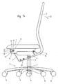
- the base 5 has a plurality of rollers 8 overlapping base 7, which carries a vertically oriented in the operating position shown column 6.
- the support arm 3 is fixed in a rotationally fixed manner in the embodiments shown.
- non-rotating means that the support arm 3 can not be rotated or pivoted about a horizontal axis or about a vertical axis relative to the column 6.
- a rotation of the seat 1 and the backrest 2, relative to the base frame 5, is made possible by the column 6 is mounted rotatably about a vertical axis in the base 7.
- the pivoting movement of the backrest in the direction 22 is made possible by the spiral spring 4.
- the spiral spring 4 also brings through its elastic properties defined opposing forces.
- the guide bracket 11 is designed substantially rigid in all embodiments shown. This means that it does not undergo a functionally essential for the function deformation during pivoting of the backrest 2 or seat plate 1 with normal use of the chair. In particular, it is advantageously provided that the guide bracket 11 is made stiffer than the spiral spring (s) 4.
- the backrest 2 is integrally formed with the support arm 3 and the two bending springs 4 as a component.
- the bending springs 4, as well as the entire support arm 3 are on the backrest 2 facing side of the imaginary and in Fig. 1 drawn vertical straight line 10 which extends through the farthest from the backrest 2 point of attachment of the support arm 3 on the base frame 5.
- the bending spring 4 is designed with respect to its cross-section and its material composition so that it provides over its longitudinal extent substantially all the necessary for the pivoting movement in direction 22 deformation.
- the backrest 2 and the remaining support arm 3 remain substantially undeformed.
- the pivoting movement 2 of the backrest can be made free of any joints connecting the backrest and the base.
- the spiral spring 4 is, as in the other embodiments, arranged below the seat plate 1.
- the seat plate 1 is in the first embodiment in its rear, the backrest facing area via a pivot member 16 pivotally connected to the support arm 3 connected.
- the pivot member 16 is pivotable about a horizontal position in the operating position 15 'relative to the support arm 3 and pivotable about an operating position horizontal axis 15 relative to the seat plate 1.
- the seat plate 1 is in its rear, the backrest 2 facing area still supported in a guide 17 provided with stops in the guide bracket 11.
- the limited by the stops 17 guide track is designed here as a slot 18. It falls to the rear, so here in the direction of the backrest 2 and the support arm 3 out.
- Favorable here are angles between 40 ° and 50 ° to the horizontal.
- axes 15 "guided in the oblong hole 18 of the guide bracket 11 are arranged coaxially with the axis of rotation 15 of the pivoting member 16 in or on the seat plate 1. If instead of the in Fig. 4 shown centrally arranged pivot member 16, two corresponding externally arranged on the support arm 3 pivot members are used, they can be mounted directly on the axes 15 "rotatable.
- the seat plate 1 is in its front region, ie in its, preferably in the horizontal direction, facing away from the backrest 2 half, supported in a second guide track of the guide bracket 11 via horizontal pivot axes 12.
- This front guide track in turn has a front and a rear stop 13.
- This guideway is designed as a slot 14 in the example shown. In a reversal of the embodiment shown, it would also be possible to execute the oblong hole 14 or another guide track with the stops 13 in the seat plate 1 and to fix the pivot axes 12 correspondingly in the guide bracket 11.
- Fig. 1 shows the inventively designed swivel chair in the rest position.
- Fig. 2 shows the same swivel chair in the maximum deflected position, which is achieved when a person sitting on the chair leans back accordingly.
- a synchronized movement of seat plate 1 and backrest 2 is performed when reclining a person sitting on the chair.
- the mechanism is conveniently designed so that the pivot angle of the backrest 2 relative to the starting position according to Fig. 1
- the position of the stops 13 and 17 is preferably selected so that the backrest 2 a maximum swing angle of 24 ° and the seat plate 1 can perform a maximum swing angle of 8 ° .
- the seat plate 1 is thereby tilted along the predetermined by the slots 14 and 18 guideways against the horizontal.
- the front guide track or the slot 14 is conveniently slightly backwards, ie inclined in the direction of the backrest 2, sloping to the horizontal. Conveniently, this is an angle of at most 10 °, preferably at most 5 °, to the horizontal. Alternatively, a completely horizontal design of the front guide track or the slot 14 may be provided.
- Fig. 3 shows the most essential components of this embodiment in an exploded view.
- the region of the spiral spring 4 characterized by the tapered cross section is represented by a clamp.
- Fig. 4 shows the back view of this office chair.
- the symmetrical lateral arrangement of the guide bracket 11 and the configuration of the support arm 3 with the two bending springs 4 can be seen here particularly well
- the number of support arms 3 and bending springs 4 can vary depending on the design and design wishes.
- the second embodiment according to the Fig. 5 to 8 is similar in its basic structure of the already explained first embodiment. Therefore, only the essential differences are discussed. These are in the storage of the rear part of the seat plate 1. This is no longer, as in the first embodiment guided in the guide pin 11, but attached via swivel joints with horizontal axes 15 on the support arm 3. Despite this difference, the second embodiment can perform an equivalent synchronous movement between seat plate 1 and backrest 2 when pivoting back in the direction 22.
- the limitation of the pivoting angle learns the system through the respective rear of the stops 13 of the likewise designed as a slot 14 front guideways.
- the maximum angle and the transmission ratio between pivoting of the seat plate 1 and the backrest 2 correspond to the details of the first embodiment.
- Fig. 5 again shows the rest position and Fig.
- Fig. 7 an exploded view of the essential parts
- Fig. 8 a rear view.
- the front pivot axes 12 are no longer covered by the rear pivot axes 15 as in the first embodiment.
- the latter are arranged here below the seat plate on the support arm 3.
- FIGS. 9 and 10 show a third and a fourth embodiment, each based on modifications of the variants already explained.
- Fig. 9 shows how to replace in the first embodiment, the integrally formed on the support arm 3 and the backrest 2 bending springs 4 by one or more acting as a bending spring leaf spring (s) 9 or by appropriate leaf spring assemblies.
- the leaf spring (s) or leaf spring packet (e) are preferably arranged detachably in the connection region 19 on the remaining support arm 3 and fixed on the other side by a likewise preferably detachable connection to the pillar 6.
- the compounds of the leaf spring (s) 9 with the column 6 and the rest of the support arm 3 are realized here as screwed. But it can also be a riveting, gluing o. The like. Be provided.
- the function of this embodiment according to Fig. 9 corresponds to what was said for the first exemplary embodiment, so that further explanations or illustrations can be dispensed with.
- Fig. 10 is based in essential parts on the second embodiment according to the Fig. 5 to 8 , Again, however, the integrally formed on the remaining support arm 3 bending spring 4 is replaced by one or more leaf spring (s) 9.
- the function corresponds to the turn to the Fig. 5 to 8 Said.
- the fifth embodiment according to the FIGS. 11 and 12 shows a further modification of the second embodiment according to Fig. 5 to 8 ,
- the C-shaped design of the guide bracket 11 of the other embodiments has been omitted in a side view.
- the guide bracket 11 according to this variant is guided by the column 6 directly to the front slot 14.
- the remaining structure and its function corresponds to that of the embodiment according to the Fig. 5 to 8 ,
- Fig. 13 shows an example of a section along the cutting plane AA Fig. 12 by the bending spring 4.
- This shows a preferred embodiment of the material structure of the spiral spring 4 and / or the support arm 5 and / or the backrest 2.
- These can, as in Fig. 13 shown, from a core portion 20 with fiber-reinforced plastic and a surrounding shell region 21 also made of plastic, but without fibers, be executed. This is just one example. It is equally possible to dispense with the fiber reinforcement with appropriate choice of material. For the production also does not necessarily have to be used plastic.
- the components can also be made of metal, wood or other materials.
- the sixth embodiment of the invention shows Fig. 14 the unloaded seating, Fig. 15 the loaded seating with swiveled backrest 2 and Fig. 16 some important items in exploded view.
- the backrest 2 via the support arm 3 is not directly but indirectly mounted on the base frame 5 attached to the guide bracket 11 on the base frame 5.
- the support arm 3 and the bending spring 4 directly on the underframe, z. B. on the column 6, to attach.
- the screw 23 shown here, with which the spiral spring 4 is mounted on the guide bracket 11, does not necessarily have to be present. It is even conceivable to perform carrier arm, bending spring and guide bracket 11 in one piece or with other means, such as. B. gluing or riveting or the like to connect with each other.
- the rear, the backrest 2 facing part of the seat plate 1 is articulated via the horizontal pivot axis 15 in the operating position on the support arm 3.
- the support arm 3 and the spiral spring 4 are in turn made in one piece as a component, which of course does not necessarily have to be this way.
- the bending spring 4 is in any case designed with respect to its cross section and its material composition so that it provides over its longitudinal extent essentially the entire deformation necessary for the pivoting movement in direction 22.
- the backrest 2 and the remaining support arm 3 as well as the guide bracket 11 remain substantially undeformed because they are stiffer than the bending spring 4 are executed. Also in the sixth embodiment according to. of the Fig.
- the mechanism is conveniently designed so that the pivot angle of the backrest 2, based on the starting position gem.
- the position of the stops 13 is preferably selected so that the backrest 2 a maximum swing angle of 24 ° and the seat plate 1 can perform a maximum swing angle of 80 °.
- this front guide track extends in the operating position relative to the horizontal from a lower, the front edge of the seat plate 1 closer first end position obliquely upwards and rearwards to a second end position, which with respect to the front edge of the seat plate 1 in the horizontal direction further away and higher in the vertical direction lies.
- a first embodiment is in the Fig. 14 to 16 shown drawn by a solid line.
- the front guideway is formed by the slot 14, which has the end stops 13 and obliquely from the front bottom back up.
- the oblong hole 14 forming said front guide track is formed in the seat plate 1.
- the slot engages the horizontal pivot axis 12, which is mounted in the guide bracket 11. The said end positions are reached when the horizontal pivot axis 12 abuts the respective stops 13 of the slot 14.
- Fig. 14 thus shows the one end position, Fig. 15 the other.
- the connecting straight line between the centers of the pivot axis 12 arranged in the respective end position closes in the unloaded position according to FIG Fig.
- a third variant is in the Fig. 14 and 15 indicated by dashed lines.
- a pivot member 16 ' is provided, which can be pivoted about the horizontal pivot axis 12' relative to the seat plate 1 and the horizontal pivot axis 12 relative to the guide bracket 11. By pivoting this results in a non-linear but running on a circular path front guideway between, in the Fig. 14 and 15 shown end positions, which in turn are determined by the also shown in dashed lines stops 13 '.
- the variant with the pivot member 16 ' and the variant with the slot 14 represent alternatives and are usually not realized together.
- the front guide track executed in accordance with the variants mentioned raises the seat panel 1 upwards in its front area, ie away from the backrest 2, as a result of which the front part of the seat panel 1 as a whole is raised together with the person using the chair ,
- the lifting height of the front part of the seat plate 1 depends on the distance of the stops 13 and 13 'predetermined end positions and the angle of the connecting line between the centers of the end positions and the horizontal from.
- the invention is not limited to the embodiments shown. These have only an explanatory character.
- the invention need not necessarily be designed in the form of swivel chairs with a base 7, rollers 8 and a rotatable and preferably also telescopically in the vertical direction column 6. Rather, it is also possible to design chairs or benches with a chair legs having base frame according to the invention.
Applications Claiming Priority (1)
| Application Number | Priority Date | Filing Date | Title |
|---|---|---|---|
| AT7762007 | 2007-05-18 |
Publications (1)
| Publication Number | Publication Date |
|---|---|
| EP1992255A1 true EP1992255A1 (fr) | 2008-11-19 |
Family
ID=39684090
Family Applications (1)
| Application Number | Title | Priority Date | Filing Date |
|---|---|---|---|
| EP08008942A Withdrawn EP1992255A1 (fr) | 2007-05-18 | 2008-05-14 | Meubles destinés à s'asseoir |
Country Status (1)
| Country | Link |
|---|---|
| EP (1) | EP1992255A1 (fr) |
Cited By (4)
| Publication number | Priority date | Publication date | Assignee | Title |
|---|---|---|---|---|
| ES2347636A1 (es) * | 2010-02-26 | 2010-11-02 | Grupo Forma 5, S.L | Mecanismo perfeccionado para sillas de movimiento combinado de respaldo y asiento. |
| DE102013022122A1 (de) * | 2013-12-28 | 2015-07-02 | Klöber GmbH | Arbeitsstuhl mit Synchronmechanik und Biegefeder |
| WO2015161281A1 (fr) * | 2014-04-17 | 2015-10-22 | Hni Technologies Inc. | Chaise et ensembles, systèmes et procédés de commande de chaise |
| WO2019078731A1 (fr) * | 2017-10-20 | 2019-04-25 | Ekornes Asa | Module de siège |
Citations (6)
| Publication number | Priority date | Publication date | Assignee | Title |
|---|---|---|---|---|
| EP0049310A1 (fr) * | 1980-10-01 | 1982-04-14 | Wilkhahn Wilkening + Hahne GmbH + Co. | Chaise de travail |
| DE19607136A1 (de) | 1995-02-28 | 1996-08-29 | Eckhard Hansen | Stuhl |
| US5775774A (en) * | 1996-08-12 | 1998-07-07 | Okano; Hiroshi | Tilt mechanism for chairs |
| EP1352595A2 (fr) * | 2002-04-07 | 2003-10-15 | Christian Erker | Coque de siège avec dispositif de réglage de l'inclinaison et du contour |
| AT411210B (de) | 2002-03-05 | 2003-11-25 | Hansen Eckhard Dipl Ing | Stuhl |
| DE202004004800U1 (de) * | 2004-03-24 | 2004-05-27 | Metalseat S.R.L., Galliera Veneta | Verstellbarer Büro-Lehnstuhl mit Gelenk zur synchronen Bewegung des Sitzes und der Rückenlehne |
-
2008
- 2008-05-14 EP EP08008942A patent/EP1992255A1/fr not_active Withdrawn
Patent Citations (6)
| Publication number | Priority date | Publication date | Assignee | Title |
|---|---|---|---|---|
| EP0049310A1 (fr) * | 1980-10-01 | 1982-04-14 | Wilkhahn Wilkening + Hahne GmbH + Co. | Chaise de travail |
| DE19607136A1 (de) | 1995-02-28 | 1996-08-29 | Eckhard Hansen | Stuhl |
| US5775774A (en) * | 1996-08-12 | 1998-07-07 | Okano; Hiroshi | Tilt mechanism for chairs |
| AT411210B (de) | 2002-03-05 | 2003-11-25 | Hansen Eckhard Dipl Ing | Stuhl |
| EP1352595A2 (fr) * | 2002-04-07 | 2003-10-15 | Christian Erker | Coque de siège avec dispositif de réglage de l'inclinaison et du contour |
| DE202004004800U1 (de) * | 2004-03-24 | 2004-05-27 | Metalseat S.R.L., Galliera Veneta | Verstellbarer Büro-Lehnstuhl mit Gelenk zur synchronen Bewegung des Sitzes und der Rückenlehne |
Cited By (16)
| Publication number | Priority date | Publication date | Assignee | Title |
|---|---|---|---|---|
| ES2347636A1 (es) * | 2010-02-26 | 2010-11-02 | Grupo Forma 5, S.L | Mecanismo perfeccionado para sillas de movimiento combinado de respaldo y asiento. |
| DE102013022122A1 (de) * | 2013-12-28 | 2015-07-02 | Klöber GmbH | Arbeitsstuhl mit Synchronmechanik und Biegefeder |
| US10455940B2 (en) | 2014-04-17 | 2019-10-29 | Hni Technologies Inc. | Chair and chair control assemblies, systems, and methods |
| WO2015161281A1 (fr) * | 2014-04-17 | 2015-10-22 | Hni Technologies Inc. | Chaise et ensembles, systèmes et procédés de commande de chaise |
| CN106455821A (zh) * | 2014-04-17 | 2017-02-22 | Hni技术公司 | 椅子和椅子控制组件、系统和方法 |
| US9801471B2 (en) | 2014-04-17 | 2017-10-31 | Hni Technologies Inc. | Chair and chair control assemblies, systems, and methods |
| KR20200063236A (ko) * | 2017-10-20 | 2020-06-04 | 에코르네스 에이에스에이 | 시트 모듈 및 틸트 기구 |
| WO2019078730A1 (fr) * | 2017-10-20 | 2019-04-25 | Ekornes Asa | Module de siège et mécanisme d'inclinaison |
| WO2019078731A1 (fr) * | 2017-10-20 | 2019-04-25 | Ekornes Asa | Module de siège |
| CN111315260A (zh) * | 2017-10-20 | 2020-06-19 | 埃科尼斯股份公司 | 座位模块和倾斜机构 |
| CN111511252A (zh) * | 2017-10-20 | 2020-08-07 | 埃科尼斯股份公司 | 座椅模块 |
| RU2732756C1 (ru) * | 2017-10-20 | 2020-09-22 | Экорнес Аса | Модуль сиденья и механизм наклона |
| US10827842B1 (en) | 2017-10-20 | 2020-11-10 | Ekornes Asa | Seat module |
| AU2018351425B2 (en) * | 2017-10-20 | 2020-12-10 | Ekornes Asa | A seat module |
| US11122900B2 (en) | 2017-10-20 | 2021-09-21 | Ekornes Asa | Seat module and tilt mechanism |
| CN111511252B (zh) * | 2017-10-20 | 2023-09-19 | 埃科尼斯股份公司 | 座椅模块 |
Similar Documents
| Publication | Publication Date | Title |
|---|---|---|
| EP2083657B1 (fr) | Mécanisme pour chaise de bureau | |
| EP1971245B1 (fr) | Mecanisme a contact permanent | |
| EP2084992B1 (fr) | Siège et sa monture | |
| DE102012107778A1 (de) | Stuhl, insbesondere Bürostuhl | |
| DE102005029906B3 (de) | Synchronmechanik | |
| WO2011141107A1 (fr) | Mécanisme de réglage d'une force de rappel agissant sur le dossier d'un siège et siège de bureau doté d'un mécanisme de ce type | |
| EP1652505B1 (fr) | Fauteuil de traitement, en particulier fauteuil de traitement dentaire | |
| EP1632152A2 (fr) | Meuble d'assise | |
| WO2014180629A1 (fr) | Siège et système d'armature associé | |
| DE102005020247B3 (de) | Sitzmöbel, insbesondere Bürostuhl | |
| EP3741258A1 (fr) | Chaise pourvue de mécanisme d'inclinaison de l'assise | |
| EP1989961B1 (fr) | Mécanisme de synchronisation pour chaises de bureau | |
| EP1989963B1 (fr) | Siège doté d'une assise et d'un dossier | |
| EP1992255A1 (fr) | Meubles destinés à s'asseoir | |
| DE202005020080U1 (de) | Sitzmöbel mit Rückenlehne und verstellbarer Kopfstütze | |
| EP3345507B1 (fr) | Mécanisme pour une chaise | |
| EP3045078A1 (fr) | Sièges | |
| EP2561777A1 (fr) | Mécanisme synchrone pour une chaise | |
| DE202005004932U1 (de) | Bewegungsbeschlag | |
| EP2994017B1 (fr) | Mécanique synchrone | |
| CH702970B1 (de) | Stuhl mit Sitzplatte und Rückenlehne. | |
| EP1449462A1 (fr) | Chaise | |
| DE102006020660B3 (de) | Fahrzeugsitz, insbesondere Nutzfahrzeugsitz | |
| EP3528664A1 (fr) | Mécanisme synchronisé pour chaise et chaise comprenant un tel mécanisme | |
| DE102015102950A1 (de) | Sitzmöbel |
Legal Events
| Date | Code | Title | Description |
|---|---|---|---|
| PUAI | Public reference made under article 153(3) epc to a published international application that has entered the european phase |
Free format text: ORIGINAL CODE: 0009012 |
|
| AK | Designated contracting states |
Kind code of ref document: A1 Designated state(s): AT BE BG CH CY CZ DE DK EE ES FI FR GB GR HR HU IE IS IT LI LT LU LV MC MT NL NO PL PT RO SE SI SK TR |
|
| AX | Request for extension of the european patent |
Extension state: AL BA MK RS |
|
| AKX | Designation fees paid | ||
| REG | Reference to a national code |
Ref country code: DE Ref legal event code: 8566 |
|
| STAA | Information on the status of an ep patent application or granted ep patent |
Free format text: STATUS: THE APPLICATION IS DEEMED TO BE WITHDRAWN |
|
| 18D | Application deemed to be withdrawn |
Effective date: 20090520 |