EP0246691A2 - Dispositif de mesure de l'atténuation en transmission d'une fibre optique - Google Patents
Dispositif de mesure de l'atténuation en transmission d'une fibre optique Download PDFInfo
- Publication number
- EP0246691A2 EP0246691A2 EP87200853A EP87200853A EP0246691A2 EP 0246691 A2 EP0246691 A2 EP 0246691A2 EP 87200853 A EP87200853 A EP 87200853A EP 87200853 A EP87200853 A EP 87200853A EP 0246691 A2 EP0246691 A2 EP 0246691A2
- Authority
- EP
- European Patent Office
- Prior art keywords
- lwl
- transmission
- optical
- fiber
- test
- Prior art date
- Legal status (The legal status is an assumption and is not a legal conclusion. Google has not performed a legal analysis and makes no representation as to the accuracy of the status listed.)
- Granted
Links
- 239000013307 optical fiber Substances 0.000 title abstract description 14
- 238000013016 damping Methods 0.000 title description 6
- 230000005540 biological transmission Effects 0.000 claims abstract description 24
- 230000003287 optical effect Effects 0.000 claims abstract description 22
- 239000000835 fiber Substances 0.000 claims description 26
- 238000001228 spectrum Methods 0.000 claims description 3
- 238000005259 measurement Methods 0.000 abstract description 13
- 230000000694 effects Effects 0.000 description 4
- 230000008878 coupling Effects 0.000 description 2
- 238000010168 coupling process Methods 0.000 description 2
- 238000005859 coupling reaction Methods 0.000 description 2
- 238000000034 method Methods 0.000 description 2
- 230000000052 comparative effect Effects 0.000 description 1
- 230000001419 dependent effect Effects 0.000 description 1
- 230000007774 longterm Effects 0.000 description 1
- 230000010287 polarization Effects 0.000 description 1
- 230000001105 regulatory effect Effects 0.000 description 1
- 230000007704 transition Effects 0.000 description 1
Images
Classifications
-
- G—PHYSICS
- G01—MEASURING; TESTING
- G01M—TESTING STATIC OR DYNAMIC BALANCE OF MACHINES OR STRUCTURES; TESTING OF STRUCTURES OR APPARATUS, NOT OTHERWISE PROVIDED FOR
- G01M11/00—Testing of optical apparatus; Testing structures by optical methods not otherwise provided for
- G01M11/30—Testing of optical devices, constituted by fibre optics or optical waveguides
- G01M11/33—Testing of optical devices, constituted by fibre optics or optical waveguides with a light emitter being disposed at one fibre or waveguide end-face, and a light receiver at the other end-face
Definitions
- the invention relates to a device for measuring the transmission loss of an optical waveguide (LWL) with an optical transmitter and a transmission LWL, the transmission light of which is directed into a test LWL to be tested and arranged coaxially to the transmission LWL, and with an optical detector through which the output light of the test fiber is received.
- LWL optical waveguide
- the fiber to be tested is coupled to the transmitting fiber via a free-beam optical system.
- An LED serves as the transmission light source.
- Free-beam optics require a lot of adjustment to be able to bundle the transmitted light beam as precisely as possible in the test fiber.
- the invention has for its object to improve the accuracy and reproducibility of damping measurements.
- the solution is achieved in that a beam-expanding element is arranged between the output surface of the transmitting optical fiber and the input surface of the test optical fiber.
- the light emerging from the transmitting optical fiber is coupled into the coaxially aligned measuring optical fiber via an element for beam expansion, tolerance-related errors in the coaxiality can only have a greatly reduced and practically negligible effect.
- tolerance-related errors in the coaxiality can only have a greatly reduced and practically negligible effect.
- the remaining received light component e.g. when using an LED as a transmission light source, it is completely sufficient to be able to receive sufficiently large measurement signals with conventional optical detectors, for example with a photodiode.
- the beam expansion is achieved in a particularly simple manner in that the output surface of the transmitting optical fiber and the input surface of the test optical fiber are spaced apart from one another by more than 100 pm. Use is made of the fact that there is an optical waveguide guided beam expands as soon as it leaves the optical fiber in a homogeneous medium such as air.
- a distance of 500-600 ⁇ m has proven to be particularly advantageous. This results in a good compromise between achievable accuracy and the remaining light intensity in the test fiber.
- a selected distance should be set approximately exactly with each new measurement. This is advantageously done in that the input surface of the test fiber can be aligned with a reference surface of the device. It is provided according to a preferred embodiment of the invention that the reference surface of the device is formed by a plug connection element.
- the optical transmitter is an incoherent light source, in particular an LED, the transmission beam of which is guided on the route to the optical detector through a narrow-band optical filter element, in particular a bandpass or interference filter.
- the optical transmission power of the LED should be stabilized. This is possible with simple means, so that no changes in the transmitted wavelengths or light outputs occur even with temperature fluctuations or long-term effects.
- An incoherent light source is preferable because then, as with lasers, noise effects due to reflection, mode noise and polarization cannot have a distorting effect on the measurement results.
- a measurement at practically a single wavelength with a narrow bandwidth as with a laser is made possible by switching on a passive, wavelength-selective element. This can be arranged directly behind an LED, but also at any other point in front of the optical detector.
- Attenuation values are not obtained which are defined as values averaged over a certain wavelength range. Rather, several measurements can be carried out at different closely adjacent wavelengths in the wavelength range of interest of a test optical fiber, so that the wavelength dependence of the attenuation can be recognized.
- the highest attenuation occurs at the shortest wavelength that is permitted for the FO according to the specification.
- This damping value which is important in practice, can also be reliably determined, in particular if a particularly precise narrow-band filter is used, the center wavelength of which deviates from the target value by less than 3 nm.
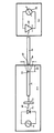
- the figure shows the relative assignment of the essential components of a device according to the invention required for measuring the transmission loss of a test optical fiber.
- the device for measuring the transmission loss of the test fiber 8 shown in the figure consists of the transmitter 7 and the receiver 9, which usually has a photodiode 10 and an electrical display element 11 contains, the display of which is dependent on the light intensity that passes from the test fiber 8 to the photodiode 10.
- an LED 2 is arranged as an incoherent transmission light source, which is controlled and regulated via a power supply circuit 1 such that the intensity and / or the center wavelength of the spectrum of the transmitted light 14 has a constant predetermined value.
- a power supply circuit 1 such that the intensity and / or the center wavelength of the spectrum of the transmitted light 14 has a constant predetermined value.
- An optical bandpass filter or an interference filter is particularly suitable.
- the input surface 13 of the test fiber 8 is at a distance 5 of 500-600 ⁇ m away from the output surface 12 of the transmission fiber 4, so that the beam diameter is widened to a diameter 6 according to the dashed lines in the plane of the input surface 13.
- Errors in the coaxiality of the transmission fiber 4 and the test fiber 8 and the spacing of their surfaces 12 and 13 have no noticeable effect on the display of the display element 11, even if they are of the order of a few ⁇ m.
- the level of the light intensity guided in the test fiber is always a constant component of the predetermined and known light intensity of the LED 2, so that after a single calibration of the transmitter 7, the input level of the test fiber is always known. A single measurement is therefore sufficient to determine the transmission loss of the test fiber 8 without the need for comparative measurements on shortened sections of the test fiber 8.
- the space between the surfaces 12 and 13 is preferably an air space, but this space could also be filled with another homogeneous, optically transparent medium.
Landscapes
- Physics & Mathematics (AREA)
- Optics & Photonics (AREA)
- Chemical & Material Sciences (AREA)
- Analytical Chemistry (AREA)
- General Physics & Mathematics (AREA)
- Optical Couplings Of Light Guides (AREA)
- Testing Of Optical Devices Or Fibers (AREA)
- Light Guides In General And Applications Therefor (AREA)
- Photometry And Measurement Of Optical Pulse Characteristics (AREA)
Applications Claiming Priority (2)
| Application Number | Priority Date | Filing Date | Title |
|---|---|---|---|
| DE3616841 | 1986-05-17 | ||
| DE19863616841 DE3616841A1 (de) | 1986-05-17 | 1986-05-17 | Vorrichtung zur messung der durchgangsdaempfung eines lichtwellenleiters |
Publications (3)
| Publication Number | Publication Date |
|---|---|
| EP0246691A2 true EP0246691A2 (fr) | 1987-11-25 |
| EP0246691A3 EP0246691A3 (en) | 1989-09-06 |
| EP0246691B1 EP0246691B1 (fr) | 1992-08-12 |
Family
ID=6301170
Family Applications (1)
| Application Number | Title | Priority Date | Filing Date |
|---|---|---|---|
| EP87200853A Expired - Lifetime EP0246691B1 (fr) | 1986-05-17 | 1987-05-11 | Dispositif de mesure de l'atténuation en transmission d'une fibre optique |
Country Status (3)
| Country | Link |
|---|---|
| EP (1) | EP0246691B1 (fr) |
| JP (1) | JPS6324138A (fr) |
| DE (2) | DE3616841A1 (fr) |
Cited By (2)
| Publication number | Priority date | Publication date | Assignee | Title |
|---|---|---|---|---|
| EP1798537A1 (fr) * | 2005-12-17 | 2007-06-20 | Schäfer Werkzeug- und Sondermaschinenbau GmbH | Appareil d'inspection final pour guides d'ondes avec viroles et procédé de son calibration |
| DE202013103148U1 (de) | 2013-07-15 | 2014-10-16 | Walo - Tl Gmbh | Vorrichtung zur Prüfung einer optischen Faser |
Families Citing this family (5)
| Publication number | Priority date | Publication date | Assignee | Title |
|---|---|---|---|---|
| DE4009160C2 (de) * | 1990-03-22 | 1993-11-18 | Wandel & Goltermann | Optisches Meßgerät für eine Mehrmodenfaser |
| DE4430512C2 (de) * | 1994-08-27 | 2000-06-29 | Bosch Gmbh Robert | Vorrichtung zum Beschalten einer verstärkenden Faser |
| DE19645542A1 (de) * | 1996-11-05 | 1998-05-07 | Lucent Tech Network Sys Gmbh | Optisches Signalübertragungssystem |
| DE10144339B4 (de) * | 2001-09-10 | 2017-07-27 | Lisa Dräxlmaier GmbH | Prüfeinrichtung zum Bestimmen der Dämpfung eines zu prüfenden Lichtwellenleiters |
| DE10322188B4 (de) * | 2003-05-16 | 2008-08-21 | Lisa Dräxlmaier GmbH | Lichtleistungsregelvorrichtung mit Modenmischer |
Family Cites Families (9)
| Publication number | Priority date | Publication date | Assignee | Title |
|---|---|---|---|---|
| JPS50114235A (fr) * | 1974-02-15 | 1975-09-08 | ||
| JPS57116234A (en) * | 1981-01-12 | 1982-07-20 | Nippon Telegr & Teleph Corp <Ntt> | Measuring method for photo loss |
| JPS5855969A (ja) * | 1981-09-29 | 1983-04-02 | 東芝ライテック株式会社 | 表示装置 |
| JPS5975134A (ja) * | 1982-10-22 | 1984-04-27 | Nippon Telegr & Teleph Corp <Ntt> | 光フアイバの光損失測定用光源 |
| JPS5988070A (ja) * | 1982-11-11 | 1984-05-21 | Besuto Kogyo Kk | 海苔の製造方法 |
| DE3327668A1 (de) * | 1983-07-30 | 1985-02-07 | Udo Dr Ing Unrau | Anordnung zur selektiven modenanregung oder modenanalyse in gradientenfasern |
| US4556314A (en) * | 1983-08-31 | 1985-12-03 | At&T Bell Laboratories | Dispersion determining method and apparatus |
| US4629316A (en) * | 1983-10-25 | 1986-12-16 | Raychem Corporation | Attenuation across optical fiber splice |
| JPS60142228A (ja) * | 1983-12-29 | 1985-07-27 | Sumitomo Electric Ind Ltd | 光フアイバの特性測定方法 |
-
1986
- 1986-05-17 DE DE19863616841 patent/DE3616841A1/de not_active Withdrawn
-
1987
- 1987-05-11 DE DE8787200853T patent/DE3781022D1/de not_active Expired - Lifetime
- 1987-05-11 EP EP87200853A patent/EP0246691B1/fr not_active Expired - Lifetime
- 1987-05-14 JP JP62116011A patent/JPS6324138A/ja active Pending
Cited By (2)
| Publication number | Priority date | Publication date | Assignee | Title |
|---|---|---|---|---|
| EP1798537A1 (fr) * | 2005-12-17 | 2007-06-20 | Schäfer Werkzeug- und Sondermaschinenbau GmbH | Appareil d'inspection final pour guides d'ondes avec viroles et procédé de son calibration |
| DE202013103148U1 (de) | 2013-07-15 | 2014-10-16 | Walo - Tl Gmbh | Vorrichtung zur Prüfung einer optischen Faser |
Also Published As
| Publication number | Publication date |
|---|---|
| DE3781022D1 (de) | 1992-09-17 |
| DE3616841A1 (de) | 1987-11-19 |
| JPS6324138A (ja) | 1988-02-01 |
| EP0246691A3 (en) | 1989-09-06 |
| EP0246691B1 (fr) | 1992-08-12 |
Similar Documents
| Publication | Publication Date | Title |
|---|---|---|
| DE69628624T2 (de) | OTDR-Gerät | |
| DE69318011T2 (de) | Optischer Koppler mit optischem Modenmischer | |
| DE3689472T2 (de) | Wellenleiter-Kommunikations- und Sensorsysteme. | |
| DE3605248C2 (fr) | ||
| CH644975A5 (de) | Lichtleitfaser-richtkoppler und dessen verwendung in einer sende-/empfangseinrichtung. | |
| DE3409207A1 (de) | Optischer sensor | |
| DE2944977A1 (de) | Optischer wellenmodenmischer | |
| EP0297669B1 (fr) | Procédé pour mesurer un rayonnement optique réfléchi | |
| DE3418298A1 (de) | Optischer entfernungssimulator | |
| DE3034942C2 (de) | Meßeinrichtung zur Bestimmung des Extinktionswertes von Laserentfernungsmessern | |
| EP0246691B1 (fr) | Dispositif de mesure de l'atténuation en transmission d'une fibre optique | |
| DE69900660T2 (de) | Vorrichtung mit einem dispersiven Lichtwellenleiter-Abzweiger | |
| DE2852614A1 (de) | Optisches messystem | |
| CH680020A5 (fr) | ||
| DE60001825T2 (de) | Optische vorrichtung mit polarisationserhaltender anschlussfaser | |
| DE2835491C3 (de) | Anordnung zum Messen von Eigenschaften von Lichtleitfasern | |
| DE2739880C2 (de) | Vorrichtung zur Fehlerortbestimmung in Lichtleitfasern oder Lichtleitfaserkabeln | |
| EP0208011B1 (fr) | Dispositif de couplage de la lumière pour la réflectrométrie optique | |
| DE69931650T2 (de) | Erzeugung einer elektromagnetischen impulsfolge zum prüfen von glasfasern | |
| DE3108239A1 (de) | "anordnung und verfahren zur messung optischer wellenlaengen" | |
| EP0259909B1 (fr) | Emetteur optique comprenant un laser à semi-conducteur et un résonateur externe | |
| DE3149616A1 (de) | Optischer depolarisator | |
| DE19637885C2 (de) | Optischer Empfänger mit einem Fasersystem mit zwei Eingängen und einem Ausgang | |
| DE4237735A1 (de) | Stufenweise variables optisches Dämpfungsglied | |
| DE3811029A1 (de) | Vorrichtung zur kernlagemessung an stirnflaechen von lichtwellenleitern |
Legal Events
| Date | Code | Title | Description |
|---|---|---|---|
| PUAI | Public reference made under article 153(3) epc to a published international application that has entered the european phase |
Free format text: ORIGINAL CODE: 0009012 |
|
| AK | Designated contracting states |
Kind code of ref document: A2 Designated state(s): DE FR GB IT |
|
| PUAL | Search report despatched |
Free format text: ORIGINAL CODE: 0009013 |
|
| AK | Designated contracting states |
Kind code of ref document: A3 Designated state(s): DE FR GB IT |
|
| 17P | Request for examination filed |
Effective date: 19900301 |
|
| 17Q | First examination report despatched |
Effective date: 19910214 |
|
| GRAA | (expected) grant |
Free format text: ORIGINAL CODE: 0009210 |
|
| AK | Designated contracting states |
Kind code of ref document: B1 Designated state(s): DE FR GB IT |
|
| REF | Corresponds to: |
Ref document number: 3781022 Country of ref document: DE Date of ref document: 19920917 |
|
| ITF | It: translation for a ep patent filed | ||
| GBT | Gb: translation of ep patent filed (gb section 77(6)(a)/1977) | ||
| ET | Fr: translation filed | ||
| PLBE | No opposition filed within time limit |
Free format text: ORIGINAL CODE: 0009261 |
|
| STAA | Information on the status of an ep patent application or granted ep patent |
Free format text: STATUS: NO OPPOSITION FILED WITHIN TIME LIMIT |
|
| 26N | No opposition filed | ||
| ITTA | It: last paid annual fee | ||
| ITPR | It: changes in ownership of a european patent |
Owner name: CAMBIO RAGIONE SOCIALE;PHILIPS ELECTRONICS N.V. |
|
| REG | Reference to a national code |
Ref country code: FR Ref legal event code: CD |
|
| REG | Reference to a national code |
Ref country code: FR Ref legal event code: TP |
|
| REG | Reference to a national code |
Ref country code: GB Ref legal event code: 732E |
|
| PGFP | Annual fee paid to national office [announced via postgrant information from national office to epo] |
Ref country code: GB Payment date: 19970410 Year of fee payment: 11 |
|
| PGFP | Annual fee paid to national office [announced via postgrant information from national office to epo] |
Ref country code: FR Payment date: 19970411 Year of fee payment: 11 |
|
| PGFP | Annual fee paid to national office [announced via postgrant information from national office to epo] |
Ref country code: DE Payment date: 19970510 Year of fee payment: 11 |
|
| PG25 | Lapsed in a contracting state [announced via postgrant information from national office to epo] |
Ref country code: GB Free format text: LAPSE BECAUSE OF NON-PAYMENT OF DUE FEES Effective date: 19980511 |
|
| PG25 | Lapsed in a contracting state [announced via postgrant information from national office to epo] |
Ref country code: FR Free format text: LAPSE BECAUSE OF NON-PAYMENT OF DUE FEES Effective date: 19980531 |
|
| GBPC | Gb: european patent ceased through non-payment of renewal fee |
Effective date: 19980511 |
|
| PG25 | Lapsed in a contracting state [announced via postgrant information from national office to epo] |
Ref country code: DE Free format text: LAPSE BECAUSE OF NON-PAYMENT OF DUE FEES Effective date: 19990302 |
|
| REG | Reference to a national code |
Ref country code: FR Ref legal event code: ST |
|
| PG25 | Lapsed in a contracting state [announced via postgrant information from national office to epo] |
Ref country code: IT Free format text: LAPSE BECAUSE OF NON-PAYMENT OF DUE FEES;WARNING: LAPSES OF ITALIAN PATENTS WITH EFFECTIVE DATE BEFORE 2007 MAY HAVE OCCURRED AT ANY TIME BEFORE 2007. THE CORRECT EFFECTIVE DATE MAY BE DIFFERENT FROM THE ONE RECORDED. Effective date: 20050511 |