EP0246444A2 - Warneinrichtung zur Anzeige des Erschöpfungszustandes eines Gasfilters - Google Patents
Warneinrichtung zur Anzeige des Erschöpfungszustandes eines Gasfilters Download PDFInfo
- Publication number
- EP0246444A2 EP0246444A2 EP87105362A EP87105362A EP0246444A2 EP 0246444 A2 EP0246444 A2 EP 0246444A2 EP 87105362 A EP87105362 A EP 87105362A EP 87105362 A EP87105362 A EP 87105362A EP 0246444 A2 EP0246444 A2 EP 0246444A2
- Authority
- EP
- European Patent Office
- Prior art keywords
- warning device
- gas filter
- heat exchanger
- measuring cell
- harmful
- Prior art date
- Legal status (The legal status is an assumption and is not a legal conclusion. Google has not performed a legal analysis and makes no representation as to the accuracy of the status listed.)
- Granted
Links
Images

Classifications
-
- A—HUMAN NECESSITIES
- A62—LIFE-SAVING; FIRE-FIGHTING
- A62B—DEVICES, APPARATUS OR METHODS FOR LIFE-SAVING
- A62B18/00—Breathing masks or helmets, e.g. affording protection against chemical agents or for use at high altitudes or incorporating a pump or compressor for reducing the inhalation effort
- A62B18/08—Component parts for gas-masks or gas-helmets, e.g. windows, straps, speech transmitters, signal-devices
- A62B18/088—Devices for indicating filter saturation
Definitions
- the invention relates to a warning device for indicating the state of exhaustion of a harmful gas from the air removing or restraining or converting into less harmful substances in connection with a breathing connection.
- the approaching end of the service life is indicated to the user by a chemical warning layer introduced into the gas filter in such a way that he perceives a correspondingly unpleasant smell on the clean air side of the gas filter as an exhaustion feature. It is a so-called odor detector.
- This warning device is disadvantageous in that, due to the possible effects of atmospheric moisture on the warning layer, premature exhaustion of the gas filter which retains the harmful gases can be simulated and the gas filter is therefore not used optimally.
- the invention is therefore based on the object of providing a warning device for displaying the state of exhaustion of a gas filter which retains harmful gases and which ensures reliable indication of exhaustion with optimal utilization of the service life of the gas filter.
- the advantages achieved by the invention consist in particular in that, on the one hand, the holding time of the gas filter can be increased considerably compared to the previously usual and, on the other hand, a reliable indication of exhaustion is given.
- the warning device 1 consists of a cartridge-like housing 2 with two opposite connecting pieces 2a and 2b, into which an electrochemical measuring cell 3, a battery 4, an electronic circuit 5, a light-emitting diode 6, an acoustic signal generator 7 and a heat exchanger 8 are housed.
- An exhalation valve 9 is provided on the housing side of the connecting piece 2a.
- the heat exchanger 8 is only required if the warning device 1 is used, for example, in a carbon monoxide gas filter, because heating of the inhaled air of over 35 ° C. is then to be expected and the electrochemical measuring cell 3 must be protected from these hot temperatures.
- the warning device 1 is to be ventilated in alternating breathing, so that the exhalation valve of the breathing connection must be sealed. In the event that the inhalation temperature is below 35 ° C, no heat exchanger is required in warning device 1. The consequence of this is that the warning device 1 then does not have an exhalation valve 9, since the warning device 1 does not have to be ventilated in alternating breathing because of the lack of a heat exchanger.
- electrochemical measuring cells for the detection of carbon monoxide, chlorine, hydrogen sulfide, hydrocyanic acid and oxygen, which can be used in the warning device 1 for the corresponding gas filter.
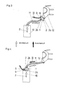
- FIGS. 3 to 5 how the warning device 1 can be installed in a filter device.
- the cartridge-like housing 2 of the warning device 1 is connected on the one hand with the connection piece 2a to the breathing hose 11 leading to the gas filter 10 and on the other hand with the connection piece 2b directly to the full face mask 12.
- the gas filter 10 can, for. B. can also be a filter canister.
- Carbon monoxide retaining gas filter is as follows: The gas filter 10 is ventilated in one direction, ie the inhaled air I flows through the gas filter and through the warning device 1 into the full face mask 12 of the user.
- the exhaled air II then passes the warning device 1 to behind the heat exchanger 8 and flows out via the exhalation valve 9. From this it is clear that the warning device 1 is ventilated in pendulum breathing.
- the heat exchanger 8 is cooled by the exhaled air II, so that the hot inhaled air I is cooled from the gas filter 10 when inhaled again, and advantageously to below 40 C, for example, in order to ensure proper functioning of the electrochemical measuring cell 3 when the inhaled air is above a bypass, not shown in the drawing by diffusion through a Teflon membrane reaches the inside of the measuring cell 3.
- the measuring cell works on the principle of electrochemical oxidation and serves as a measuring element for the detection of harmful concentrations of harmful gases in the inhaled air, which can no longer be retained or removed by the upstream gas filter 10 in the event of exhaustion.
- the measuring cell 3 measures a certain harmful pollutant concentration, which indicates that the pollutant retained in the gas filter breaks through, which means that the gas filter 10 is exhausted.
- the warning device 1 with the connection piece 2a is connected directly to the gas filter 10 designed as a filter sleeve and with the connection piece 2b to the breathing tube 11 with the full mask 12.
- the warning device 1 is connected between the gas filter 10 and the full face mask 12.
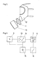
- Fig. 6 shows the electronic circuit arrangement of the warning device 1 as a block diagram, consisting of the electrochemical measuring cell 3 which is followed by a signal amplifier 13 and this a threshold switch 14 and the light emitting diode 6 and the acoustic signal generator 7.
- a battery 15 is provided with a battery monitor 16, which indicates the consumption of the battery on the light-emitting diode 6 and the signal transmitter 7 optically and acoustically.
- the switching threshold of the threshold switch 14 is set to the measurement signal corresponding to the alarm-triggering measurement value, which corresponds to a certain harmful gas concentration which indicates the end of the usage time of the gas filter 10.
- the measurement signal coming from the measuring cell 3 exceeds the set switching threshold (alarm threshold) of the threshold switch 16, its output becomes conductive and the LED 6 and the signal transmitter 7 are activated and trigger the optical and acoustic alarm.
- the gas filter 10 is then used up.
Landscapes
- Health & Medical Sciences (AREA)
- Pulmonology (AREA)
- General Health & Medical Sciences (AREA)
- Business, Economics & Management (AREA)
- Emergency Management (AREA)
- Investigating Or Analyzing Materials By The Use Of Electric Means (AREA)
- Respiratory Apparatuses And Protective Means (AREA)
- Investigating Or Analysing Materials By Optical Means (AREA)
Abstract
Description
- Die Erfindung betrifft eine Warneinrichtung zur Anzeige des Erschöpfungszustandes eines Schadgase aus der Luft entfernenden bzw zurückhaltenden oder in weniger schädliche Stoffe umwandelnden Gasfilters in Verbindung mit einem Atemanschluß.
- Bei einer bekannten Warneinrichtung dieser Art wird das nahende Ende der Gebrauchsdauer durch eine in das Gasfilter eingebrachte chemische Warnschicht dem Benutzer derart angezeigt, indem er als Erschöpfungsmerkmal einen entsprechend unangenehmen Geruch auf der Reinluftseite des Gasfilters wahrnimmt. Es handelt sich hierbei um einen sogenannten Geruchswarner.
- Diese Warneinrichtung ist insofern nachteilig, weil durch evtl. Einwirkungen von Luftfeuchtigkeit auf die Warnschicht eine vorzeitige Erschöpfung des Schadgase zurückhaltenden Gasfilters vorgetäuscht werden kann und somit das Gasfilter nicht optimal ausgenutzt wird.
- Der Erfindung liegt daher die Aufgabe zugrunde, eine Warneinrichtung zur Anzeige des Erschöpfungszustandes eines Schadgase zurückhaltenden Gasfilters zu schaffen, die eine sichere Erschöpfungsanzeige bei optimaler Ausnutzung der Gebrauchsdauer des Gasfilters gewährleistet.
- Diese Aufgabe wird erfindungsgemäß durch die kennzeichnenden Merkmale des Anspruchs 1 gelöst.
- Die mit der Erfindung erzielten Vorteile bestehen insbesondere darin, daß einerseits die Haltezeit des Gasfilters gegenüber der bisher üblichen erheblich erhöht werden kann und andererseits eine sichere Erschöpfungsanzeige gegeben ist.
- Ein Ausführungsbeispiel der Erfindung ist in der Zeichnung dargestellt und wird im folgenden näher beschrieben. Es zeigt:
- Fig. 1 eine Seitenansicht des die Warneinrichtung aufnehmenden Gehäuses, teilweise geschnitten
- Fig. 2 eine Draufsicht auf das Gehäuse mit Warneinrichtung bei abgenommenem Gehäusedeckel,
- Fig. 3 ein Ausführungsbeispiel eines Filtergerätes, wobei die Warneinrichtung direkt an die Vollmaske angeschlossen und über einen Atemschlauch mit einer Filterbüchse verbunden ist,
- Fig. 4 ein Ausführungsbeispiel eines Filtergerätes, wobei die Warneinrichtung direkt an die Filterbüchse angeschlossen und über den Atemschlauch mit der Vollmaske verbunden ist,
- Fig. 5 ein Ausführungsbeispiel des Filtergerätes, wobei die Warneinrichtung zwischen einem Gasfilter und der Vollmaske geschaltet ist, und
- Fig. 6 ein Blockschaltbild der Warneinrichtung
- Wie aus den Figuren 1 und 2 ersichtlich ist, besteht die Warneinrichtung 1 aus einem patronenartigen Gehäuse 2 mit zwei gegenüberliegenden Anschlußstutzen 2a und 2b, in das eine elektrochemische Meßzelle 3, eine Batterie 4, eine elektronische Schaltung 5, eine Leuchtdiode 6, ein akustischer Signalgeber 7 und ein Wärmeaustauscher 8 untergebracht sind. An der Gehäuseseite des Anschlußstutzens 2a ist ein Ausatemventil 9 vorgesehen. Der Wärmeaustauscher 8 ist nur dann erforderlich, wenn die Warneinrichtung 1 beispielsweise bei einem Kohlenmonoxid-Gasfilter eingesetzt wird, weil dann mit einer Erwärmung der Einatemluft von über 35° C zu rechnen ist und die elektrochemische Meßzelle 3 vor diesen heißen Temperaturen geschützt werden muß. Bei Verwendung eines Wärmeaustauschers 8 ist die Warneinrichtung 1 in Pendelatmung zu beatmen, so daß das Ausatemventil des Atemanschlusses dichtgesetzt werden muß. Für den Fall, daß die Einatemtemperatur unter 35° C liegt, ist in der Warneinrichtung 1 kein Wärmeaustauscher erforderlich. Das hat zur Folge, daß die Warneinrichtung 1 dann auch kein Ausatemventil 9 aufweist, da wegen des fehlenden Wärmeaustauschers die Warneinrichtung 1 nicht in Pendelatmung beatmet werden muß.
Es gibt bereits elektrochemische Meßzellen zum Nachweis von Kohlenmonoxid, Chlor, Schwefelwasserstoff, Blausäure und Sauerstoff, die in die Warneinrichtung 1 für die entsprechenden Gasfilter einsetzbar sind. - Aus den Figuren 3 bis 5 ist ersichtlich, wie die Warneinrichtung 1 in einem Filtergerät eingebaut werden kann.
So ist in Fig. 3 das patronenartige Gehäuse 2 der Warneinrichtung 1 einerseits mit dem Anschlußstutzen 2a an dem zum Gasfilter 10 führenden Atemschlauch 11 angeschlossen und andererseits mit dem Anschlußstutzen 2b direkt an die Vollmaske 12. Das Gasfilter 10 kann z. B. auch eine Filterbüchse sein. Die Funktionsweise der derart in ein Filtergerät eingebauten Warneinrichtung, und zwar bei einem z. B. Kohlenmonoxid zurückhaltenden Gasfilter, ist folgende:
Das Gasfilter 10 wird in einer Richtung beatmet, d. h. die Einatemluft I strömt durch das Gasfilter und durch die Warneinrichtung 1 in die Vollmaske 12 des Benutzers. Die Ausatemluft II passiert dann die Warneinrichtung 1 bis hinter den Wärmeaustauscher 8 und strömt über das Ausatemventil 9 ab. Hieraus wird deutlich, daß die Warneinrichtung 1 in Pendelatmung beatmet wird. Der Wärmeaustauscher 8 wird durch die Ausatemluft II gekühlt, so daß beim erneuten Einatmen die heiße Einatemluft I aus dem Gasfilter 10 abgekühlt wird, und zwar vorteilhaft auf beispielsweise unter 40 C, um eine einwandfreie Funktion der elektrochemischen Meßzelle 3 zu gewährleisten, wenn die Einatemluft über einen in der Zeichnung nicht dargestellten Bypaß durch Diffusion durch eine Teflonmembran in das Innere der Meßzelle 3 gelangt.
Die Meßzelle arbeitet nach dem Prinzip der elektrochemischen Oxidation und dient als Meßelement zum Nachweis schädlicher Schadgaskonzentrationen in der Einatemluft, die von dem vorgeschalteten Gasfilter 10 im Falle des Erschöpfungszustandes nicht mehr zurückgehalten bzw. entfernt werden können. Mit anderen Worten: die Meßzelle 3 mißt eine bestimmte schädliche Schadstoffkonzentration, die anzeigt, daß der im Gasfilter zurückgehaltene Schadstoff durchbricht, was bedeutet, daß das Gasfilter 10 erschöpft ist. - In Fig. 4 ist die Warneinrichtung 1 mit dem Anschlußstutzen 2a direkt an den als Filterbüchse ausgebildeten Gasfilter 10 und mit dem Anschlußstutzen 2b an den Atemschlauch 11 mit der Vollmaske 12 angeschlossen.
- In Fig. 5 ist die Warneinrichtung 1 zwischen dem Gasfilter 10 und der Vollmaske 12 geschaltet.
- Fig. 6 zeigt die elektronische Schaltungsanordnung der Warneinrichtung 1 als Blockschaltbild, bestehend aus der elektrochemischen Meßzelle 3 der ein Signalverstärker 13 und diesem ein Schwellwertschalter 14 sowie die Leuchtdiode 6 und der akustische Signalgeber 7 nachgeschaltet ist. Zur Energieversorgung der Schaltungsanordnung ist eine Batterie 15 mit einer Batterieüberwachung 16 vorgesehen, die den Verbrauch der Batterie an der Leuchtdiode 6 und dem Signalgeber 7 optisch und akustisch anzeigt.
Die Schaltschwelle des Schwellwertschalters 14 ist auf das den alarmauslösenden Meßwert entsprechende Meßsignal eingestellt, das einer bestimmten Schadgas-Konzentration entspricht, die das Ende der Gebrauchszeit des Gasfilters 10 anzeigt. Überschreitet beispielsweise das von der Meßzelle 3 kommende Meßsignal die eingestellte Schaltschwelle (Alarmschwelle) des Schwellwertschalters 16, so wird dessen Ausgang leitend und die Leuchtdiode 6 sowie der Signalgeber 7 werden aktiviert und lösen den optischen und akustischen Alarm aus. Das Gasfilter 10 ist dann verbraucht.
Claims (7)
Applications Claiming Priority (2)
| Application Number | Priority Date | Filing Date | Title |
|---|---|---|---|
| DE3613512 | 1986-04-22 | ||
| DE3613512A DE3613512C3 (de) | 1986-04-22 | 1986-04-22 | Elektrische Warneinrichtung zur Anzeige des Erschöpfungszustandes eines Schadgase zurückhaltenden Gasfilters |
Publications (3)
| Publication Number | Publication Date |
|---|---|
| EP0246444A2 true EP0246444A2 (de) | 1987-11-25 |
| EP0246444A3 EP0246444A3 (en) | 1990-08-22 |
| EP0246444B1 EP0246444B1 (de) | 1993-02-03 |
Family
ID=6299213
Family Applications (1)
| Application Number | Title | Priority Date | Filing Date |
|---|---|---|---|
| EP87105362A Expired - Lifetime EP0246444B1 (de) | 1986-04-22 | 1987-04-10 | Warneinrichtung zur Anzeige des Erschöpfungszustandes eines Gasfilters |
Country Status (3)
| Country | Link |
|---|---|
| US (1) | US4873970A (de) |
| EP (1) | EP0246444B1 (de) |
| DE (2) | DE3613512C3 (de) |
Cited By (3)
| Publication number | Priority date | Publication date | Assignee | Title |
|---|---|---|---|---|
| FR2677765A1 (fr) * | 1991-06-17 | 1992-12-18 | Commissariat Energie Atomique | Procede de surveillance de l'etat de saturation d'une masse de charbon active filtrante d'un dispositif de filtration et cartouche de masque respiratoire en portant application. |
| WO1996012523A1 (en) * | 1994-10-24 | 1996-05-02 | Minnesota Mining And Manufacturing Company | Exposure indicator with alarm signal |
| WO1996012524A1 (en) * | 1994-10-24 | 1996-05-02 | Minnesota Mining And Manufacturing Company | Exposure indicating apparatus |
Families Citing this family (49)
| Publication number | Priority date | Publication date | Assignee | Title |
|---|---|---|---|---|
| DE3818052A1 (de) * | 1988-05-27 | 1989-12-07 | Geraetebau Gmbh | Atemschutzmaske |
| DE3838531A1 (de) * | 1988-11-14 | 1990-05-17 | Wolfgang Gerigk | Vorrichtung zur detektierung von verseuchter und vergifteter atemluft |
| DE4009107A1 (de) * | 1990-03-21 | 1991-09-26 | Auergesellschaft Gmbh | Warneinrichtung mit einer messzelle und alarmgebern zur anzeige des erschoefpungszustandes eines gasfilters |
| CA2020503C (en) * | 1990-07-05 | 1998-11-17 | Jacques Lesage | Chemical cartridge for protective respiratory mask |
| USD339658S (en) | 1991-05-02 | 1993-09-21 | Air-Ace Oy | Respirator |
| DE4132680C2 (de) * | 1991-10-01 | 1994-02-10 | Draegerwerk Ag | Atemschutzmaske mit Innenhalbmaske und Schadstoffindikator |
| DE4133235A1 (de) * | 1991-10-07 | 1993-04-08 | Draegerwerk Ag | Geblaeseunterstuetztes atemschutzgeraet mit einem aufsetzbaren steuerteil |
| US5117821A (en) * | 1991-10-18 | 1992-06-02 | White George M | Hunting mask with breath odor control system |
| DE4214239C2 (de) * | 1992-04-30 | 1994-06-16 | Draegerwerk Ag | Atemschutzmaske mit einem indikator |
| US5338430A (en) * | 1992-12-23 | 1994-08-16 | Minnesota Mining And Manufacturing Company | Nanostructured electrode membranes |
| WO1995009676A1 (en) * | 1993-10-01 | 1995-04-13 | Minnesota Mining And Manufacturing Company | Speech transmission adaptor for use with a respirator mask |
| US5906203A (en) * | 1994-08-01 | 1999-05-25 | Safety Equipment Sweden Ab | Breathing apparatus |
| TW287952B (de) * | 1994-08-31 | 1996-10-11 | Lifepro Inc | |
| US5856198A (en) * | 1994-12-28 | 1999-01-05 | Extraction Systems, Inc. | Performance monitoring of gas-phase air filters |
| US5676133A (en) * | 1995-06-14 | 1997-10-14 | Apotheus Laboratories, Inc. | Expiratory scavenging method and apparatus and oxygen control system for post anesthesia care patients |
| US5878743A (en) * | 1996-09-23 | 1999-03-09 | Respironics, Inc. | Pressure sensitive flow control valve |
| US6003511A (en) * | 1996-11-18 | 1999-12-21 | Medlis Corp. | Respiratory circuit terminal for a unilimb respiratory device |
| DE19650897A1 (de) * | 1996-12-07 | 1998-06-10 | T E M Tech Entwicklung Und Man | Apparat und Verfahren zur Erhöhung der Sicherheit von Atemschutzmasken |
| US6096267A (en) * | 1997-02-28 | 2000-08-01 | Extraction Systems, Inc. | System for detecting base contaminants in air |
| WO1998038508A1 (en) * | 1997-02-28 | 1998-09-03 | Extraction Systems, Inc. | System for detecting amine and other basic molecular contamination in a gas |
| US6186140B1 (en) * | 1997-03-14 | 2001-02-13 | 3M Innovative Properties Company | Respiratory filter element having a storage device for keeping track of filter usage and a system for use therewith |
| US5937852A (en) * | 1997-04-08 | 1999-08-17 | The Board Of Regents Of The University Of Texas System | Apparatus for induction of inhaled pharmacological agent by a pediatric patient |
| US6207460B1 (en) | 1999-01-14 | 2001-03-27 | Extraction Systems, Inc. | Detection of base contaminants in gas samples |
| JP2002539442A (ja) | 1999-03-17 | 2002-11-19 | テー・エー・エム!テクニシェ・エントビクルンゲン・ウント・メニジメント・ゲゼルシャフト・ミット・ベシュレンクテル・ハフツング | 空気中に含まれるガスおよび煙のセンサ装置と検出方法 |
| DE19911867C2 (de) * | 1999-03-17 | 2002-02-21 | T E M Techn Entwicklungen Und | Sensorsystem zur Detektion von Gasen und Dämpfen in Luft |
| US6761169B2 (en) * | 2000-08-17 | 2004-07-13 | Vase Technology | Bi/multi-directional filter cartridge and filter platform for mounting the cartridge thereon |
| US20040182394A1 (en) * | 2003-03-21 | 2004-09-23 | Alvey Jeffrey Arthur | Powered air purifying respirator system and self contained breathing apparatus |
| US20060048777A1 (en) * | 2003-03-21 | 2006-03-09 | Interspiro, Inc. | Apparatus and method for providing breathable air and bodily protection in a contaminated environment |
| US7647927B2 (en) * | 2003-08-22 | 2010-01-19 | Wilcox Industries Corp. | Self-contained breathing system |
| US7100423B2 (en) * | 2003-09-04 | 2006-09-05 | Midwest Research Institute | Method and apparatus for monitoring particles in a flowing gas |
| US20100139661A1 (en) * | 2003-12-18 | 2010-06-10 | Scott Technologies, Inc. | Air breathing hose with integrated electrical wiring |
| US20070105494A1 (en) * | 2005-11-08 | 2007-05-10 | Esco Micro Pte Ltd | Ductless fume hood with improved filter monitoring system and extended filter life |
| US8336543B2 (en) * | 2009-05-22 | 2012-12-25 | 3M Innovative Properties Company | Filter cartridge having cover for masking service life indicator |
| US8365723B2 (en) * | 2009-05-22 | 2013-02-05 | 3M Innovative Properties Company | Filter cartridge having cone of visibility for end-of-service-life-indicator (ESLI) |
| US8225782B2 (en) * | 2009-05-22 | 2012-07-24 | 3M Innovative Properties Company | Filter cartridge having location-registered view window for end-of-service-life-indicator (ESLI) |
| US8372186B2 (en) * | 2009-08-14 | 2013-02-12 | Gregory J. Dobbyn | Ductless fume hood gas monitoring and detection system |
| CA2789649C (en) * | 2010-02-26 | 2018-04-03 | Intertechnique | Method for determining partial pressure of a gaseous constituent and regulator of breathing mask for aircraft occupant |
| CN102892451B (zh) | 2010-03-25 | 2017-03-08 | 瑞思迈巴黎股份有限公司 | 用于呼吸治疗装置的可呼吸气体进气口控制设备 |
| EP2553436B1 (de) | 2010-04-02 | 2020-03-04 | 3M Innovative Properties Company | Filtersysteme mit optischen analytsensoren und optischen lesegeräten |
| CN107441831A (zh) * | 2010-08-06 | 2017-12-08 | 斯科特科技股份有限公司 | 提供空气净化过滤器的使用寿命结束指示的传感器装置 |
| US8616205B2 (en) | 2010-10-06 | 2013-12-31 | Honeywell International Inc. | Respirator with end-of-service-life detection |
| US9011584B2 (en) | 2011-08-25 | 2015-04-21 | Honeywell International Inc. | End of service life indicator for respirator |
| US9079049B2 (en) | 2011-11-02 | 2015-07-14 | Honeywell International Inc. | Respirators with a sacrificial cartridge for end of service life indication |
| EP2790812B1 (de) | 2011-12-12 | 2018-11-14 | 3M Innovative Properties Company | Systeme zur anzeige des lebensdauerendes für geschichtete filterpatronen |
| US9283411B2 (en) | 2013-04-19 | 2016-03-15 | Honeywell International Inc. | Gas sensing drift compensation using gas self-referencing for end of service life indication for respirators |
| EP2875847B1 (de) * | 2013-11-26 | 2020-03-11 | Naphtachimie S.A. | Gesicherte Atemschutzvorrichtung |
| CN107072338A (zh) | 2014-09-05 | 2017-08-18 | 霍尼韦尔国际公司 | 一次性面罩的寿命终止指示器 |
| ITUB201594612U1 (it) * | 2015-11-17 | 2017-05-17 | Spasciani S P A | Dispositivo di protezione individuale delle vie respiratorie provvisto di sistema di allarme. |
| GB2579210A (en) * | 2018-11-23 | 2020-06-17 | World Wide Welding Ltd | Powered air personal respirator |
Family Cites Families (10)
| Publication number | Priority date | Publication date | Assignee | Title |
|---|---|---|---|---|
| US1320935A (en) * | 1919-11-04 | schwartz | ||
| GB170404A (en) * | 1920-07-20 | 1921-10-20 | Leonard Angelo Levy | A carbon monoxide respirator |
| US1474205A (en) * | 1921-10-11 | 1923-11-13 | Mine Safety Appliances Co | Gas mask |
| AT155693B (de) * | 1934-09-21 | 1939-03-10 | Pirelli | Vorrichtung zum Anzeigen des Erschöpfungszustandes von Gasfiltern und -schutzgeräten. |
| FR843542A (fr) * | 1937-09-29 | 1939-07-05 | Pirelli | Dispositif pour la signalisation de l'épuisement des filtres antigaz |
| DE1721541U (de) * | 1954-05-22 | 1956-05-03 | Draegerwerk Ag | Vorrichtung zur anzeige der erschoepfung eines atemfilters. |
| DE1120774B (de) * | 1960-04-26 | 1961-12-28 | Mine Safety Appliances Co | Detektorzelle zum Messen der Konzentration einer Gaskomponente |
| US3902485A (en) * | 1974-02-08 | 1975-09-02 | Richard A Wallace | Chemically activated warning system |
| DE2529058A1 (de) * | 1975-06-30 | 1977-02-03 | Richard A Wallace | Sicherheitswarnvorrichtung |
| US4051006A (en) * | 1976-03-22 | 1977-09-27 | Beckman Instruments, Inc. | Portable electrochemical cell structure |
-
1986
- 1986-04-22 DE DE3613512A patent/DE3613512C3/de not_active Expired - Fee Related
-
1987
- 1987-04-10 EP EP87105362A patent/EP0246444B1/de not_active Expired - Lifetime
- 1987-04-10 DE DE8787105362T patent/DE3783944D1/de not_active Expired - Fee Related
-
1989
- 1989-03-10 US US07/323,069 patent/US4873970A/en not_active Expired - Lifetime
Cited By (3)
| Publication number | Priority date | Publication date | Assignee | Title |
|---|---|---|---|---|
| FR2677765A1 (fr) * | 1991-06-17 | 1992-12-18 | Commissariat Energie Atomique | Procede de surveillance de l'etat de saturation d'une masse de charbon active filtrante d'un dispositif de filtration et cartouche de masque respiratoire en portant application. |
| WO1996012523A1 (en) * | 1994-10-24 | 1996-05-02 | Minnesota Mining And Manufacturing Company | Exposure indicator with alarm signal |
| WO1996012524A1 (en) * | 1994-10-24 | 1996-05-02 | Minnesota Mining And Manufacturing Company | Exposure indicating apparatus |
Also Published As
| Publication number | Publication date |
|---|---|
| DE3783944D1 (de) | 1993-03-18 |
| EP0246444B1 (de) | 1993-02-03 |
| DE3613512A1 (de) | 1987-10-29 |
| DE3613512C2 (de) | 1994-09-29 |
| US4873970A (en) | 1989-10-17 |
| DE3613512C3 (de) | 1994-09-29 |
| EP0246444A3 (en) | 1990-08-22 |
Similar Documents
| Publication | Publication Date | Title |
|---|---|---|
| EP0246444A2 (de) | Warneinrichtung zur Anzeige des Erschöpfungszustandes eines Gasfilters | |
| US3773044A (en) | Chemical breathing apparatus with alarm device | |
| DE3742639C2 (de) | Atemgerät mit geschlossenem Kreislauf | |
| DE4132680C2 (de) | Atemschutzmaske mit Innenhalbmaske und Schadstoffindikator | |
| EP0343521B1 (de) | Atemschutzmaske | |
| US9011584B2 (en) | End of service life indicator for respirator | |
| US4440162A (en) | Soda lime half life indicator | |
| DE3109658A1 (de) | Elektrisch steuerbares atemschutzgeraet nach dem kreislaufprinzip | |
| DE2136968A1 (de) | Feuermeldesystem | |
| EP0447619B1 (de) | Warneinrichtung mit einer Messzelle und Alarmgebern zur Anzeige des Erschöpfungszustandes eines Gasfilters | |
| DE10318384A1 (de) | Inkubator mit einer Sauerstoffdosierung | |
| US4155361A (en) | Air regenerating apparatus | |
| EP1165186B1 (de) | Verfahren und sensorvorrichtung zur detektion von in luft enthaltenen gasen oder dämpfen | |
| DE2428352A1 (de) | Anordnung zur bestimmung der alkoholkonzentration der (tiefen) lungenluft | |
| DD220227A1 (de) | Schaltungsanordnung zur elektronischen steuerung und ueberwachung eines atemgasbefeuchters | |
| DE2147718C3 (de) | Kohlendioxid-Warngerät | |
| DE19911869B4 (de) | Neuartige Atemschutzmaske mit Sensor-Mikrosystem und Verfahren zum Betreiben derselben | |
| DE19650897A1 (de) | Apparat und Verfahren zur Erhöhung der Sicherheit von Atemschutzmasken | |
| DE2425647C3 (de) | Sensor für CO2 -Meßgerät | |
| EP2539225A1 (de) | Kreislauftauchgerät mit einem mundstück | |
| Damez et al. | Safety problems in ozonation plants | |
| DE1163153B (de) | Warnvorrichtung fuer Druckgasatemschutzgeraete | |
| DE102004022988A1 (de) | Gasmischvorrichtung für Kompressorstationen und Verfahren zum sicheren Betrieb | |
| DE3838531A1 (de) | Vorrichtung zur detektierung von verseuchter und vergifteter atemluft | |
| DE1648989C3 (de) | Kohlendioxid-Warngerät zu Überwachungszwecken bei der Inhalationsnarkose |
Legal Events
| Date | Code | Title | Description |
|---|---|---|---|
| PUAI | Public reference made under article 153(3) epc to a published international application that has entered the european phase |
Free format text: ORIGINAL CODE: 0009012 |
|
| 17P | Request for examination filed |
Effective date: 19870421 |
|
| AK | Designated contracting states |
Kind code of ref document: A2 Designated state(s): BE DE FR GB IT NL SE |
|
| PUAL | Search report despatched |
Free format text: ORIGINAL CODE: 0009013 |
|
| AK | Designated contracting states |
Kind code of ref document: A3 Designated state(s): BE DE FR GB IT NL SE |
|
| 17Q | First examination report despatched |
Effective date: 19911114 |
|
| ITTA | It: last paid annual fee | ||
| GRAA | (expected) grant |
Free format text: ORIGINAL CODE: 0009210 |
|
| AK | Designated contracting states |
Kind code of ref document: B1 Designated state(s): BE DE FR GB IT NL SE |
|
| ITF | It: translation for a ep patent filed | ||
| REF | Corresponds to: |
Ref document number: 3783944 Country of ref document: DE Date of ref document: 19930318 |
|
| GBT | Gb: translation of ep patent filed (gb section 77(6)(a)/1977) |
Effective date: 19930218 |
|
| ET | Fr: translation filed | ||
| PLBI | Opposition filed |
Free format text: ORIGINAL CODE: 0009260 |
|
| 26 | Opposition filed |
Opponent name: DRAEGERWERK AG Effective date: 19930922 |
|
| NLR1 | Nl: opposition has been filed with the epo |
Opponent name: DRAEGERWERK AG |
|
| EAL | Se: european patent in force in sweden |
Ref document number: 87105362.5 |
|
| PLBN | Opposition rejected |
Free format text: ORIGINAL CODE: 0009273 |
|
| STAA | Information on the status of an ep patent application or granted ep patent |
Free format text: STATUS: OPPOSITION REJECTED |
|
| 27O | Opposition rejected |
Effective date: 19950429 |
|
| NLR2 | Nl: decision of opposition | ||
| PGFP | Annual fee paid to national office [announced via postgrant information from national office to epo] |
Ref country code: SE Payment date: 19990315 Year of fee payment: 13 |
|
| PGFP | Annual fee paid to national office [announced via postgrant information from national office to epo] |
Ref country code: GB Payment date: 19990323 Year of fee payment: 13 |
|
| PGFP | Annual fee paid to national office [announced via postgrant information from national office to epo] |
Ref country code: BE Payment date: 19990414 Year of fee payment: 13 |
|
| PGFP | Annual fee paid to national office [announced via postgrant information from national office to epo] |
Ref country code: FR Payment date: 19990415 Year of fee payment: 13 |
|
| PGFP | Annual fee paid to national office [announced via postgrant information from national office to epo] |
Ref country code: NL Payment date: 19990429 Year of fee payment: 13 |
|
| PG25 | Lapsed in a contracting state [announced via postgrant information from national office to epo] |
Ref country code: GB Free format text: LAPSE BECAUSE OF NON-PAYMENT OF DUE FEES Effective date: 20000410 |
|
| PG25 | Lapsed in a contracting state [announced via postgrant information from national office to epo] |
Ref country code: SE Free format text: LAPSE BECAUSE OF NON-PAYMENT OF DUE FEES Effective date: 20000411 |
|
| PG25 | Lapsed in a contracting state [announced via postgrant information from national office to epo] |
Ref country code: BE Free format text: LAPSE BECAUSE OF NON-PAYMENT OF DUE FEES Effective date: 20000430 |
|
| BERE | Be: lapsed |
Owner name: AUERGESELLSCHAFT G.M.B.H. Effective date: 20000430 |
|
| PG25 | Lapsed in a contracting state [announced via postgrant information from national office to epo] |
Ref country code: NL Free format text: LAPSE BECAUSE OF NON-PAYMENT OF DUE FEES Effective date: 20001101 |
|
| GBPC | Gb: european patent ceased through non-payment of renewal fee |
Effective date: 20000410 |
|
| EUG | Se: european patent has lapsed |
Ref document number: 87105362.5 |
|
| PG25 | Lapsed in a contracting state [announced via postgrant information from national office to epo] |
Ref country code: FR Free format text: LAPSE BECAUSE OF NON-PAYMENT OF DUE FEES Effective date: 20001229 |
|
| NLV4 | Nl: lapsed or anulled due to non-payment of the annual fee |
Effective date: 20001101 |
|
| REG | Reference to a national code |
Ref country code: FR Ref legal event code: ST |
|
| PGFP | Annual fee paid to national office [announced via postgrant information from national office to epo] |
Ref country code: DE Payment date: 20020117 Year of fee payment: 16 |
|
| PG25 | Lapsed in a contracting state [announced via postgrant information from national office to epo] |
Ref country code: DE Free format text: LAPSE BECAUSE OF NON-PAYMENT OF DUE FEES Effective date: 20031101 |
|
| PG25 | Lapsed in a contracting state [announced via postgrant information from national office to epo] |
Ref country code: IT Free format text: LAPSE BECAUSE OF NON-PAYMENT OF DUE FEES Effective date: 20050410 |