EP0246424A2 - Axialgleitlager für eine Anlaufschulter einer Getriebewelle - Google Patents
Axialgleitlager für eine Anlaufschulter einer Getriebewelle Download PDFInfo
- Publication number
- EP0246424A2 EP0246424A2 EP87104416A EP87104416A EP0246424A2 EP 0246424 A2 EP0246424 A2 EP 0246424A2 EP 87104416 A EP87104416 A EP 87104416A EP 87104416 A EP87104416 A EP 87104416A EP 0246424 A2 EP0246424 A2 EP 0246424A2
- Authority
- EP
- European Patent Office
- Prior art keywords
- lubricating oil
- oil grooves
- section
- axial sliding
- sliding bearing
- Prior art date
- Legal status (The legal status is an assumption and is not a legal conclusion. Google has not performed a legal analysis and makes no representation as to the accuracy of the status listed.)
- Granted
Links
- 239000010687 lubricating oil Substances 0.000 claims abstract description 36
- 239000002245 particle Substances 0.000 claims abstract description 12
- 239000000463 material Substances 0.000 claims description 4
- 230000005540 biological transmission Effects 0.000 abstract description 4
- 238000005299 abrasion Methods 0.000 description 4
- -1 ferrous metals Chemical class 0.000 description 2
- 239000000835 fiber Substances 0.000 description 2
- 239000002184 metal Substances 0.000 description 2
- 229910052751 metal Inorganic materials 0.000 description 2
- 238000004062 sedimentation Methods 0.000 description 2
- 229910000906 Bronze Inorganic materials 0.000 description 1
- 229910000831 Steel Inorganic materials 0.000 description 1
- 239000010974 bronze Substances 0.000 description 1
- 239000012876 carrier material Substances 0.000 description 1
- KUNSUQLRTQLHQQ-UHFFFAOYSA-N copper tin Chemical compound [Cu].[Sn] KUNSUQLRTQLHQQ-UHFFFAOYSA-N 0.000 description 1
- 238000004519 manufacturing process Methods 0.000 description 1
- 230000002688 persistence Effects 0.000 description 1
- 239000010959 steel Substances 0.000 description 1
- 229920001169 thermoplastic Polymers 0.000 description 1
- 239000004416 thermosoftening plastic Substances 0.000 description 1
- 210000002105 tongue Anatomy 0.000 description 1
Images
Classifications
-
- F—MECHANICAL ENGINEERING; LIGHTING; HEATING; WEAPONS; BLASTING
- F16—ENGINEERING ELEMENTS AND UNITS; GENERAL MEASURES FOR PRODUCING AND MAINTAINING EFFECTIVE FUNCTIONING OF MACHINES OR INSTALLATIONS; THERMAL INSULATION IN GENERAL
- F16H—GEARING
- F16H57/00—General details of gearing
- F16H57/04—Features relating to lubrication or cooling or heating
- F16H57/048—Type of gearings to be lubricated, cooled or heated
- F16H57/0482—Gearings with gears having orbital motion
-
- F—MECHANICAL ENGINEERING; LIGHTING; HEATING; WEAPONS; BLASTING
- F16—ENGINEERING ELEMENTS AND UNITS; GENERAL MEASURES FOR PRODUCING AND MAINTAINING EFFECTIVE FUNCTIONING OF MACHINES OR INSTALLATIONS; THERMAL INSULATION IN GENERAL
- F16C—SHAFTS; FLEXIBLE SHAFTS; ELEMENTS OR CRANKSHAFT MECHANISMS; ROTARY BODIES OTHER THAN GEARING ELEMENTS; BEARINGS
- F16C17/00—Sliding-contact bearings for exclusively rotary movement
- F16C17/04—Sliding-contact bearings for exclusively rotary movement for axial load only
-
- F—MECHANICAL ENGINEERING; LIGHTING; HEATING; WEAPONS; BLASTING
- F16—ENGINEERING ELEMENTS AND UNITS; GENERAL MEASURES FOR PRODUCING AND MAINTAINING EFFECTIVE FUNCTIONING OF MACHINES OR INSTALLATIONS; THERMAL INSULATION IN GENERAL
- F16C—SHAFTS; FLEXIBLE SHAFTS; ELEMENTS OR CRANKSHAFT MECHANISMS; ROTARY BODIES OTHER THAN GEARING ELEMENTS; BEARINGS
- F16C33/00—Parts of bearings; Special methods for making bearings or parts thereof
- F16C33/02—Parts of sliding-contact bearings
- F16C33/04—Brasses; Bushes; Linings
- F16C33/06—Sliding surface mainly made of metal
- F16C33/10—Construction relative to lubrication
- F16C33/1025—Construction relative to lubrication with liquid, e.g. oil, as lubricant
- F16C33/1045—Details of supply of the liquid to the bearing
- F16C33/105—Conditioning, e.g. metering, cooling, filtering
-
- F—MECHANICAL ENGINEERING; LIGHTING; HEATING; WEAPONS; BLASTING
- F16—ENGINEERING ELEMENTS AND UNITS; GENERAL MEASURES FOR PRODUCING AND MAINTAINING EFFECTIVE FUNCTIONING OF MACHINES OR INSTALLATIONS; THERMAL INSULATION IN GENERAL
- F16C—SHAFTS; FLEXIBLE SHAFTS; ELEMENTS OR CRANKSHAFT MECHANISMS; ROTARY BODIES OTHER THAN GEARING ELEMENTS; BEARINGS
- F16C33/00—Parts of bearings; Special methods for making bearings or parts thereof
- F16C33/02—Parts of sliding-contact bearings
- F16C33/04—Brasses; Bushes; Linings
- F16C33/06—Sliding surface mainly made of metal
- F16C33/10—Construction relative to lubrication
- F16C33/1025—Construction relative to lubrication with liquid, e.g. oil, as lubricant
- F16C33/106—Details of distribution or circulation inside the bearings, e.g. details of the bearing surfaces to affect flow or pressure of the liquid
- F16C33/1065—Grooves on a bearing surface for distributing or collecting the liquid
-
- F—MECHANICAL ENGINEERING; LIGHTING; HEATING; WEAPONS; BLASTING
- F16—ENGINEERING ELEMENTS AND UNITS; GENERAL MEASURES FOR PRODUCING AND MAINTAINING EFFECTIVE FUNCTIONING OF MACHINES OR INSTALLATIONS; THERMAL INSULATION IN GENERAL
- F16C—SHAFTS; FLEXIBLE SHAFTS; ELEMENTS OR CRANKSHAFT MECHANISMS; ROTARY BODIES OTHER THAN GEARING ELEMENTS; BEARINGS
- F16C2361/00—Apparatus or articles in engineering in general
- F16C2361/61—Toothed gear systems, e.g. support of pinion shafts
Definitions
- the invention relates to an axial sliding bearing for a starting shoulder of a transmission shaft of the type explained in the preamble of claim 1.
- the known axial slide bearing has the disadvantage. that the arcuate lubricating oil grooves take up a significant part of the bearing surface, thereby reducing the possible bearing load. Such an arrangement is therefore not broke for an axial sliding bearing for a thrust shoulder of a gear shaft, in which only a limited annular bearing surface is available.
- a radial slide bearing made of thermoplastic for rotating shaft in which lubricating oil grooves with a semicircular cross section which run obliquely to the bearing surface are intended to collect dirt particles and to discharge them with the lubricating oil or to hold them in place via a brush-like fiber bed arranged in the lubricating oil grooves .
- This known radial slide bearing has the disadvantage that it can only be used where a constant flow of lubricating oil can be maintained or, on the other hand, is complex due to the arrangement of brush-like fiber beds, since these must be securely fixed in the lubricating oil grooves.
- the object of the invention is to improve an axial slide bearing of the type mentioned in the preamble of claim 1 in such a way that particles carried in the lubricating oil, such as abrasion and chips, and not only of ferrous metals but in particular of non-ferrous metals, reliably from the area of the effective bearing surface removed and held. According to the invention, this object is achieved in that an axial sliding bearing of the type explained in the preamble of patent claim 1 has the features indicated in the characterizing part of patent claim 1.
- the arcuate lubricating oil grooves arranged in the annular bearing surface have an initial section which lies approximately in the direction of the resultant of the tangential and centrifugal force acting on a particle carried in the lubricating oil and have an end section which runs somewhat radially inward are carried in the lubricating oil Particles are driven into the lubricating oil grooves by the forces acting on them, where they are held in the closed end section.
- the larger mass of the dirt particles ensures that they remain in the end sections of the lubricating oil grooves while the lubricating oil can flow off through the gap in the bearing surface.
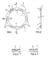
- the axial slide bearing 1 shown in FIGS. 1 and 2 is provided for a starting shoulder of a gear shaft and accordingly has an annular bearing surface 2.
- the axial sliding bearing 1 is in this case fixed on the inner circumference 3 or also on the outer circumference 4 axially bent tongues 5 on the component that absorbs the axial load against rotation.
- the axial plain bearing 1 can be made in a manner known per se completely from a plain bearing material such as. B. bronze or preferably, as shown in the drawings, from a carrier material 6, such as. B. steel sheet with a plated layer of bearing material 7, such as. B. Bronze.
- a plurality of lubricating oil grooves 8 are provided in the annular bearing surface 2, which are open against the direction of rotation of the transmission shaft, which is indicated by the arrow 9, and extend in an arcuate manner and with a rectangular cross section to their closed end.
- the arcuate lubricating oil grooves 8 have an initial section 10 which lies approximately in the direction of the resultant of the tagential and centrifugal forces acting on a particle carried in the lubricating oil and have an end section 11 which extends somewhat radially inwards.
- particles entrained in the lubricating oil are driven outwards as a result of their greater persistence, where they catch the initial sections 10 of the lubricating oil grooves 8 and continue into the end sections 11, where they adhere to the wall of the Collect lubricating oil grooves 8 as a result of the centrifugal force and wedge each other.
- the lubricating oil which is also forced into the lubricating oil grooves 8, can reach the bearing surface 2 via the gap of the axial sliding bearing.
- a lubricating oil groove according to the invention is shown in cross section, which is produced by fine stamping. Care must be taken that walls of the lubricating oil groove 8 which are as vertical as possible are achieved at a depth of about half a millimeter.
Landscapes
- Engineering & Computer Science (AREA)
- General Engineering & Computer Science (AREA)
- Mechanical Engineering (AREA)
- Chemical & Material Sciences (AREA)
- Oil, Petroleum & Natural Gas (AREA)
- Sliding-Contact Bearings (AREA)
- General Details Of Gearings (AREA)
Abstract
Description
- Die Erfindung bezieht sich auf ein Axialgleitlager für eine Anlaufschulter einer Getriebewelle der im Oberbegriff des Patentanspruchs 1 erläuterten Art.
- Aus der DE-OS 24 13 020 ist ein Axialgleitlager für eine rotierende Welle, insbesondere für Gasturbinen, bekannt, das in seiner scheibenförmigen Lagerfläche mit einer Vielzahl von entgegen der Drehrichtung offenen, bogenförmigen Schmierölnuten mit rechteckigem Querschnitt und geschlossenen Enden versehen ist.
- Das bekannte Axialgleitlager weist den Nachteil auf,. daß die bogenförmigen Schmierölnuten einen erheblichen Teil der Lagerfläche einnehmen, wodurch die mögliche Lagerbelastung verringert wird. Eine solche Anordnung ist daher für ein Axialgleitlager für eine Anlaufschulter einer Getriebewelle, bei der nur eine begrenzte ringförmige Lagerfläche zur Verfügung steht, nicht brachbar.
- Aus der DE-OS 26 39 735 ist ein Radialgleitlager aus thermoplastischem Kunststoff für rotierende Welle zu entnehmen, bei dem schräg zur Lagerfläche verlaufende Schmierölnuten mit halbrundem Querschnitt Schmutzpartikel sammeln und mit dem Schmieröl ableiten sollen bzw über ein in den Schmierölnuten angeordnetes, bürstenartiges Faserbett festhalten sollen.
- Diese bekannte Radialgleitlager weist den Nachteil auf, daß es einerseits nur dort anwendbar ist, wo ein ständiger Schmierölstrom aufrecht erhalten werden kann oder andererseits durch die Anordnung von bürstenartigen Faserbetten aufwendig ist, da diese sicher in den Schmierölnuten festgelegt werden müssen.
- Aus der DE-OS 27 28 249 ist ein Vorschlag zum Entfernen von Partikeln und Abrieb aus Gleitlagern zu entnehmen, der jedoch nur auf das Entfernen magnetisch anziehbarer Partikel abgestellt ist. Auf Seite 2, Absatz 2, der Beschreibung wird darauf hingewiesen, daß es dem Fachmann zwar bekannt ist, Partikel und Abrieb aus ölgeschmierten Lagerungen durch Sedimentation zu entfernen, daß die hierfür erforderlichen Ruhezonen und Sedimentationszeiten schwer konstruktiv zu lösen sind.
- Die Aufgabe der Erfindung ist es, ein Axialgleitlager der im Oberbegriff des Patentanspruchs 1 genannten Art derart zu verbessern, daß im Schmieröl mitgeführte Partikel, wie Abrieb und Späne, und zwar nicht nur von Eisenmetallen sondern insbesondere von Nichteisenmetallen, sicher aus dem Bereich der wirksamen Lagerfläche entfernt und festgehalten werden. Gemäß der Erfindung wird diese Aufgabe gelöst, indem ein Axialgleitlager der im Oberbegriff des Patentanspruchs 1 erläuterten Art die im Kennzeichenteil des Patentanspruchs 1 aufgezeigten Merkmale aufweist.
- Dadurch, daß die in der ringförmigen Lagerfläche angeordneten bogenförmigen Schmierölnuten einen Anfangsabschnitt aufweisen, der etwa in Richtung der Resultierenden der auf ein im Schmieröl mitgeführtes Partikel einwirkenden Tangential- und Zentrifugalkraft liegt und einen Endabschnitt aufweisen, der etwas radial nach einwärts verläuft, werden im Schmieröl mitgeführte Partikel durch die auf sie einwirkenden Kräfte in die Schmierölnuten hineingetrieben, wo sie im geschlossenen Endabschnitt festgehalten werden. Die größere Masse der Schmutzpartikel sorgt dafür, daß diese in den Endabschnitten der Schmierölnuten verbleiben während das Schmieröl über den Spalt der Lagerfläche abfließen kann.
- In den Ansprüchen 2 und 3 sind zweckmäßige Maßnahmen zum Herstellen der erfindungsgemäßen Schmierölnuten erläutert.
- Die Erfindung wird anhand eines in der beiliegenden Zeichnungen gezeigten Ausführungsbeispiels näher erläutert. Es zeigt
- Fig. 1 eine Draufsicht auf ein Axialgleitlager für eine Anlaufschulter einer Getriebewelle gemäß der Erfindung;
- Fig. 2 einen vertikalen Schnitt entlang der Linie II-II in Fig. 1;
- Fig. 3 einen Schnitt entlang der Linie III-III in Fig. 1 und
- Fig. 4 einen ähnlichen Schnitt wie Fig. 3 durch eine weitere Ausführungsform.
- Das in den Fig. 1 und 2 gezeigte Axialgleitlager 1 ist für eine Anlaufschulter einer Getriebewelle vorgesehen und weist dementsprechend eine ringförmige Lagerfläche 2 auf. Das Axialgleitlager 1 wird hierbei über am inneren Umfang 3 oder auch am äußeren Umfang 4 vorgesehene axial abgebogene Zungen 5 an dem die Axiallast aufnehmenden Bauteil gegen Drehung festgelegt.
- Das Axialgleitlager 1 kann hierbei in an sich bekannter Weise vollständig aus einem Gleitlagermaterial wie z. B. Bronze bestehen oder aber vorzugsweise, wie in den Zeichnungen gezeigt, aus einem Trägermaterial 6, wie z. B. Stahlblech mit einer aufplattierten Schicht aus Lagermaterial 7, wie z. B. Bronze, hergestellt sein.
- Gemäß der Erfindung sind in der ringförmigen Lagerfläche 2 eine Vielzahl von Schmierölnuten 8 vorgesehen, die entgegen der Drehrichtung der Getriebewelle, die durch den Pfeil 9 angedeutet ist, offen sind und bogenförmig und mit rechteckigem Querschnitt zu ihrem geschlossenen Ende verlaufen.
- Gemäß der Erfindung weisen die bogenförmigen Schmierölnuten 8 jedoch einen Anfangsabschnitt 10 auf, der etwa in Richtung der Resultierenden der auf ein im Schmieröl mitgeführtes Partikel einwirkenden Tagential- und Zentrifugalkräfte liegt und weisen einen Endabschnitt 11 auf, der etwas radial nach einwärts verläuft.
- Dadurch werden im Schmieröl mitgeführte Partikel, wie von der Fertigung zurückgebliebene Späne oder durch Verschleiß bedingter Abrieb, infolge ihres höheren Beharrungsvermögens nach außen getrieben, wo sie die Anfangsabschnitte 10 der Schmierölnuten 8 abfangen und in die Endabschnitte 11 weiterführen, wo sie sich an der Wandung der Schmierölnuten 8 infolge der einwirkenden Fliehkraft ansammeln und gegenseitig verkeilen. Das gleichfalls in die Schmierölnuten 8 hineingedrängte Schmieröl kann über den Spalt des Axialgleitlagers auf die Lagerfläche 2 gelangen.
- In Fig. 3 ist eine Ausführungsform einer erfindungsgemäßen Schmierölnut im Querschnitt gezeigt, die durch Feinprägen hergestellt wird. Dabei muß darauf geachtet werden, daß bei einer Tiefe von etwa einem halben Millimeter möglichst senkrechte Wandungen der Schmierölnut 8 erzielt werden.
- Bei der in Fig. 4 gezeigten Schmierölnut 8ʹ ist diese durch Materialabtragen mittels eines Fingerfräsers hergestellt, was zwar teurer ist aber mit größerer Sicherheit eine rechtwinklige Wandung der Schmierölnut einzuhalten erlaubt und eventuell sogar eine hinterschnittene Form der Schmierölnutwandung ermöglicht.
Claims (3)
Applications Claiming Priority (2)
| Application Number | Priority Date | Filing Date | Title |
|---|---|---|---|
| DE19863617087 DE3617087A1 (de) | 1986-05-21 | 1986-05-21 | Axialgleitlager fuer eine anlaufschulter einer getriebewelle |
| DE3617087 | 1986-05-21 |
Publications (3)
| Publication Number | Publication Date |
|---|---|
| EP0246424A2 true EP0246424A2 (de) | 1987-11-25 |
| EP0246424A3 EP0246424A3 (en) | 1988-06-01 |
| EP0246424B1 EP0246424B1 (de) | 1990-08-22 |
Family
ID=6301300
Family Applications (1)
| Application Number | Title | Priority Date | Filing Date |
|---|---|---|---|
| EP87104416A Expired - Lifetime EP0246424B1 (de) | 1986-05-21 | 1987-03-25 | Axialgleitlager für eine Anlaufschulter einer Getriebewelle |
Country Status (2)
| Country | Link |
|---|---|
| EP (1) | EP0246424B1 (de) |
| DE (2) | DE3617087A1 (de) |
Cited By (7)
| Publication number | Priority date | Publication date | Assignee | Title |
|---|---|---|---|---|
| AT391926B (de) * | 1987-11-13 | 1990-12-27 | Glyco Metall Werke | Axialgleitlager aus schichtwerkstoff und verfahren zu seiner herstellung |
| US5007746A (en) * | 1989-12-26 | 1991-04-16 | Federal-Mogul Corporation | Thrust bearing with resilient retention tang |
| US8281912B2 (en) * | 2008-03-18 | 2012-10-09 | Schaeffler Technologies AG & Co. KG | Stampable thrust washer with flow cutouts |
| WO2014055255A1 (en) * | 2012-10-02 | 2014-04-10 | Borgwarner Inc. | End face oil configuration for journal bearings |
| CN104454980A (zh) * | 2014-10-22 | 2015-03-25 | 张永斌 | 新型节能向心滑动轴承 |
| WO2021004803A1 (de) * | 2019-07-08 | 2021-01-14 | Miba Industrial Bearings Germany Gmbh | Hydrodynamisches gleitlager |
| WO2022043123A1 (de) * | 2020-08-28 | 2022-03-03 | Rolls-Royce Deutschland Ltd & Co Kg | Gleitlagervorrichtung, getriebevorrichtung mit einer gleitlagervorrichtung und gasturbinentriebwerk mit einer gleitlagervorrichtung |
Families Citing this family (6)
| Publication number | Priority date | Publication date | Assignee | Title |
|---|---|---|---|---|
| DE3820061A1 (de) * | 1988-06-13 | 1989-12-14 | Glyco Metall Werke | Gleitlager |
| JP2527161Y2 (ja) * | 1989-03-28 | 1997-02-26 | ジャトコ 株式会社 | 遊星歯車装置のキャリア組立体 |
| DE19700339C2 (de) * | 1996-01-30 | 2001-06-13 | Federal Mogul Wiesbaden Gmbh | Haupt- oder Pleuellagerelement |
| DE10034123C2 (de) * | 2000-07-13 | 2003-03-20 | Bosch Gmbh Robert | Wellenlagerung |
| DE102012210694A1 (de) * | 2012-06-25 | 2014-01-02 | Schaeffler Technologies AG & Co. KG | Abgewinkelte Anlaufscheibe eines Planetentriebs |
| DE102018110015B3 (de) | 2018-04-26 | 2019-07-18 | Schaeffler Technologies AG & Co. KG | Anlaufscheibe sowie hiermit ausgestattetes Planetengetriebe |
Family Cites Families (10)
| Publication number | Priority date | Publication date | Assignee | Title |
|---|---|---|---|---|
| DE339649C (de) * | 1917-05-30 | 1921-07-30 | Josef Desenberg | Gleitflaeche mit zahlreichen, quer zur Gleitrichtung verlaufenden Aussparungen |
| US2362667A (en) * | 1942-05-15 | 1944-11-14 | Westinghouse Electric & Mfg Co | Thrust bearing |
| US3377113A (en) * | 1965-08-03 | 1968-04-09 | Rotron Mfg Co | Hydrodynamic bearing |
| FR2032998A5 (de) * | 1969-02-24 | 1970-11-27 | Skf Svenska Kullagerfab Ab | |
| US3597027A (en) * | 1969-02-28 | 1971-08-03 | Gen Motors Corp | Thrust bearing |
| US3841720A (en) * | 1973-04-02 | 1974-10-15 | Ford Motor Co | Thrust bearing assembly |
| DE2612252A1 (de) * | 1976-03-23 | 1977-10-06 | Hackewitz Friedrich Wilhelm Vo | Selbstdruckerzeugendes gleitlager |
| DE2639735A1 (de) * | 1976-09-03 | 1978-03-16 | Fenaro Ferch & Co Kg | Gleitlager aus thermoplastischem kunststoff fuer translatorisch bewegte oder rotierende maschinen- oder geraeteteile |
| DE2728249C3 (de) * | 1977-06-23 | 1980-06-12 | Dornier System Gmbh, 7990 Friedrichshafen | Gleitlagerung |
| JPS59164823U (ja) * | 1983-04-20 | 1984-11-05 | 大同メタル工業株式会社 | 外周面に斜め油溝を有する巻きブシユ軸受 |
-
1986
- 1986-05-21 DE DE19863617087 patent/DE3617087A1/de not_active Withdrawn
-
1987
- 1987-03-25 EP EP87104416A patent/EP0246424B1/de not_active Expired - Lifetime
- 1987-03-25 DE DE8787104416T patent/DE3764397D1/de not_active Expired - Lifetime
Cited By (10)
| Publication number | Priority date | Publication date | Assignee | Title |
|---|---|---|---|---|
| AT391926B (de) * | 1987-11-13 | 1990-12-27 | Glyco Metall Werke | Axialgleitlager aus schichtwerkstoff und verfahren zu seiner herstellung |
| US5007746A (en) * | 1989-12-26 | 1991-04-16 | Federal-Mogul Corporation | Thrust bearing with resilient retention tang |
| US8281912B2 (en) * | 2008-03-18 | 2012-10-09 | Schaeffler Technologies AG & Co. KG | Stampable thrust washer with flow cutouts |
| WO2014055255A1 (en) * | 2012-10-02 | 2014-04-10 | Borgwarner Inc. | End face oil configuration for journal bearings |
| CN104718387A (zh) * | 2012-10-02 | 2015-06-17 | 博格华纳公司 | 用于轴颈轴承的端面油构造 |
| CN104454980A (zh) * | 2014-10-22 | 2015-03-25 | 张永斌 | 新型节能向心滑动轴承 |
| CN104454980B (zh) * | 2014-10-22 | 2017-04-12 | 张永斌 | 节能向心滑动轴承 |
| WO2021004803A1 (de) * | 2019-07-08 | 2021-01-14 | Miba Industrial Bearings Germany Gmbh | Hydrodynamisches gleitlager |
| US11920631B2 (en) | 2019-07-08 | 2024-03-05 | Miba Industrial Bearings Germany Osterode Gmbh | Hydrodynamic slide bearing |
| WO2022043123A1 (de) * | 2020-08-28 | 2022-03-03 | Rolls-Royce Deutschland Ltd & Co Kg | Gleitlagervorrichtung, getriebevorrichtung mit einer gleitlagervorrichtung und gasturbinentriebwerk mit einer gleitlagervorrichtung |
Also Published As
| Publication number | Publication date |
|---|---|
| DE3764397D1 (de) | 1990-09-27 |
| DE3617087A1 (de) | 1987-11-26 |
| EP0246424B1 (de) | 1990-08-22 |
| EP0246424A3 (en) | 1988-06-01 |
Similar Documents
| Publication | Publication Date | Title |
|---|---|---|
| DE69403135T2 (de) | Universaler Segmenttreibbelag für Kupplungen | |
| DE2843198C2 (de) | ||
| EP0246424A2 (de) | Axialgleitlager für eine Anlaufschulter einer Getriebewelle | |
| EP0476395B1 (de) | Anlaufscheibenanordnung für Planetenräder eines Planetenradträgers | |
| EP0840027A3 (de) | Axialgleitlager | |
| DE2231175B2 (de) | Schaufelrad einer Strömungsarbeitsmaschine | |
| DE3322578C2 (de) | Sortiervorrichtung | |
| DE2535979B2 (de) | Scheibenmühle | |
| EP3091242A1 (de) | Gleitlager mit schmiernut | |
| EP0287847B1 (de) | Schneidwerkzeug | |
| DE19680800B4 (de) | Axialwälzlager | |
| DE2345487C2 (de) | Schleifende Dichtung für Pendelwälzlager | |
| DE3231005A1 (de) | Gehaeuse fuer waelzlager mit oelfoerderschmierung | |
| DE19804734A1 (de) | Planetenscheibe | |
| WO1998028077A1 (de) | Zerkleinerungsmaschine mit einem emulgator | |
| EP0960963A2 (de) | Lagerung für einen Offenend-Spinnrotor mittels Stützscheiben | |
| DE68920606T2 (de) | Vorrichtung zum Sieben von Papierstoffbrei und Flügel für die Siebvorrichtung. | |
| DE112019002338B4 (de) | Turbolader für einen Verbrennungsmotor | |
| EP3091235B1 (de) | Rotorscheibe | |
| DE4210207C1 (en) | Grinder disc with knives for fibre-shredder - has rings of teeth with radial grinding surfaces working between similar rings of teeth on stator | |
| DE2162678A1 (de) | Radial- bzw. axialrollenlager | |
| EP2556002B1 (de) | Rollenantrieb | |
| EP1232964A2 (de) | Kurvenförderer | |
| EP1148006A1 (de) | Kettenrolle einer Transportkette | |
| DE9002218U1 (de) | Wälzlager, insbesondere Getriebelager |
Legal Events
| Date | Code | Title | Description |
|---|---|---|---|
| PUAI | Public reference made under article 153(3) epc to a published international application that has entered the european phase |
Free format text: ORIGINAL CODE: 0009012 |
|
| AK | Designated contracting states |
Kind code of ref document: A2 Designated state(s): BE DE FR GB IT NL SE |
|
| PUAL | Search report despatched |
Free format text: ORIGINAL CODE: 0009013 |
|
| AK | Designated contracting states |
Kind code of ref document: A3 Designated state(s): BE DE FR GB IT NL SE |
|
| 17P | Request for examination filed |
Effective date: 19880427 |
|
| 17Q | First examination report despatched |
Effective date: 19890505 |
|
| GRAA | (expected) grant |
Free format text: ORIGINAL CODE: 0009210 |
|
| AK | Designated contracting states |
Kind code of ref document: B1 Designated state(s): BE DE FR GB IT NL SE |
|
| GBT | Gb: translation of ep patent filed (gb section 77(6)(a)/1977) | ||
| ET | Fr: translation filed | ||
| REF | Corresponds to: |
Ref document number: 3764397 Country of ref document: DE Date of ref document: 19900927 |
|
| ITF | It: translation for a ep patent filed | ||
| REG | Reference to a national code |
Ref country code: GB Ref legal event code: 746 |
|
| PLBE | No opposition filed within time limit |
Free format text: ORIGINAL CODE: 0009261 |
|
| STAA | Information on the status of an ep patent application or granted ep patent |
Free format text: STATUS: NO OPPOSITION FILED WITHIN TIME LIMIT |
|
| 26N | No opposition filed | ||
| REG | Reference to a national code |
Ref country code: FR Ref legal event code: DL |
|
| ITTA | It: last paid annual fee | ||
| REG | Reference to a national code |
Ref country code: FR Ref legal event code: ST |
|
| EAL | Se: european patent in force in sweden |
Ref document number: 87104416.0 |
|
| REG | Reference to a national code |
Ref country code: FR Ref legal event code: RN |
|
| REG | Reference to a national code |
Ref country code: FR Ref legal event code: FC |
|
| REG | Reference to a national code |
Ref country code: FR Ref legal event code: TP Ref country code: FR Ref legal event code: CD |
|
| PGFP | Annual fee paid to national office [announced via postgrant information from national office to epo] |
Ref country code: NL Payment date: 20010228 Year of fee payment: 15 |
|
| PGFP | Annual fee paid to national office [announced via postgrant information from national office to epo] |
Ref country code: SE Payment date: 20010305 Year of fee payment: 15 |
|
| PGFP | Annual fee paid to national office [announced via postgrant information from national office to epo] |
Ref country code: BE Payment date: 20010309 Year of fee payment: 15 |
|
| PGFP | Annual fee paid to national office [announced via postgrant information from national office to epo] |
Ref country code: DE Payment date: 20010313 Year of fee payment: 15 |
|
| PGFP | Annual fee paid to national office [announced via postgrant information from national office to epo] |
Ref country code: GB Payment date: 20010315 Year of fee payment: 15 |
|
| PGFP | Annual fee paid to national office [announced via postgrant information from national office to epo] |
Ref country code: FR Payment date: 20010316 Year of fee payment: 15 |
|
| PG25 | Lapsed in a contracting state [announced via postgrant information from national office to epo] |
Ref country code: DE Free format text: LAPSE BECAUSE OF THE APPLICANT RENOUNCES Effective date: 20010822 |
|
| REG | Reference to a national code |
Ref country code: GB Ref legal event code: IF02 |
|
| PG25 | Lapsed in a contracting state [announced via postgrant information from national office to epo] |
Ref country code: GB Free format text: LAPSE BECAUSE OF NON-PAYMENT OF DUE FEES Effective date: 20020325 |
|
| PG25 | Lapsed in a contracting state [announced via postgrant information from national office to epo] |
Ref country code: SE Free format text: LAPSE BECAUSE OF NON-PAYMENT OF DUE FEES Effective date: 20020326 |
|
| PG25 | Lapsed in a contracting state [announced via postgrant information from national office to epo] |
Ref country code: BE Free format text: LAPSE BECAUSE OF NON-PAYMENT OF DUE FEES Effective date: 20020331 |
|
| BERE | Be: lapsed |
Owner name: *FORD-WERKE A.G. Effective date: 20020331 |
|
| PG25 | Lapsed in a contracting state [announced via postgrant information from national office to epo] |
Ref country code: NL Free format text: LAPSE BECAUSE OF NON-PAYMENT OF DUE FEES Effective date: 20021001 |
|
| EUG | Se: european patent has lapsed |
Ref document number: 87104416.0 |
|
| GBPC | Gb: european patent ceased through non-payment of renewal fee |
Effective date: 20020325 |
|
| PG25 | Lapsed in a contracting state [announced via postgrant information from national office to epo] |
Ref country code: FR Free format text: LAPSE BECAUSE OF NON-PAYMENT OF DUE FEES Effective date: 20021129 |
|
| NLV4 | Nl: lapsed or anulled due to non-payment of the annual fee |
Effective date: 20021001 |
|
| REG | Reference to a national code |
Ref country code: FR Ref legal event code: ST |
|
| PG25 | Lapsed in a contracting state [announced via postgrant information from national office to epo] |
Ref country code: IT Free format text: LAPSE BECAUSE OF NON-PAYMENT OF DUE FEES;WARNING: LAPSES OF ITALIAN PATENTS WITH EFFECTIVE DATE BEFORE 2007 MAY HAVE OCCURRED AT ANY TIME BEFORE 2007. THE CORRECT EFFECTIVE DATE MAY BE DIFFERENT FROM THE ONE RECORDED. Effective date: 20050325 |