EP0245740B1 - Procédé et moyen pour le retard numérique de signaux ultrasonores à la réception - Google Patents
Procédé et moyen pour le retard numérique de signaux ultrasonores à la réception Download PDFInfo
- Publication number
- EP0245740B1 EP0245740B1 EP87106410A EP87106410A EP0245740B1 EP 0245740 B1 EP0245740 B1 EP 0245740B1 EP 87106410 A EP87106410 A EP 87106410A EP 87106410 A EP87106410 A EP 87106410A EP 0245740 B1 EP0245740 B1 EP 0245740B1
- Authority
- EP
- European Patent Office
- Prior art keywords
- delay
- value
- interpolator
- output
- values
- Prior art date
- Legal status (The legal status is an assumption and is not a legal conclusion. Google has not performed a legal analysis and makes no representation as to the accuracy of the status listed.)
- Expired - Lifetime
Links
- 238000000034 method Methods 0.000 title claims description 21
- 238000005070 sampling Methods 0.000 claims description 21
- 230000003111 delayed effect Effects 0.000 claims description 8
- 238000002604 ultrasonography Methods 0.000 description 42
- 230000005540 biological transmission Effects 0.000 description 2
- 238000007796 conventional method Methods 0.000 description 1
- 238000010586 diagram Methods 0.000 description 1
- 238000002592 echocardiography Methods 0.000 description 1
- 230000010354 integration Effects 0.000 description 1
- 239000000203 mixture Substances 0.000 description 1
- 238000012285 ultrasound imaging Methods 0.000 description 1
- XLYOFNOQVPJJNP-UHFFFAOYSA-N water Substances O XLYOFNOQVPJJNP-UHFFFAOYSA-N 0.000 description 1
Images
Classifications
-
- G—PHYSICS
- G01—MEASURING; TESTING
- G01S—RADIO DIRECTION-FINDING; RADIO NAVIGATION; DETERMINING DISTANCE OR VELOCITY BY USE OF RADIO WAVES; LOCATING OR PRESENCE-DETECTING BY USE OF THE REFLECTION OR RERADIATION OF RADIO WAVES; ANALOGOUS ARRANGEMENTS USING OTHER WAVES
- G01S7/00—Details of systems according to groups G01S13/00, G01S15/00, G01S17/00
- G01S7/52—Details of systems according to groups G01S13/00, G01S15/00, G01S17/00 of systems according to group G01S15/00
- G01S7/52017—Details of systems according to groups G01S13/00, G01S15/00, G01S17/00 of systems according to group G01S15/00 particularly adapted to short-range imaging
- G01S7/52046—Techniques for image enhancement involving transmitter or receiver
-
- G—PHYSICS
- G01—MEASURING; TESTING
- G01S—RADIO DIRECTION-FINDING; RADIO NAVIGATION; DETERMINING DISTANCE OR VELOCITY BY USE OF RADIO WAVES; LOCATING OR PRESENCE-DETECTING BY USE OF THE REFLECTION OR RERADIATION OF RADIO WAVES; ANALOGOUS ARRANGEMENTS USING OTHER WAVES
- G01S15/00—Systems using the reflection or reradiation of acoustic waves, e.g. sonar systems
- G01S15/88—Sonar systems specially adapted for specific applications
- G01S15/89—Sonar systems specially adapted for specific applications for mapping or imaging
- G01S15/8906—Short-range imaging systems; Acoustic microscope systems using pulse-echo techniques
- G01S15/8909—Short-range imaging systems; Acoustic microscope systems using pulse-echo techniques using a static transducer configuration
- G01S15/8915—Short-range imaging systems; Acoustic microscope systems using pulse-echo techniques using a static transducer configuration using a transducer array
- G01S15/8918—Short-range imaging systems; Acoustic microscope systems using pulse-echo techniques using a static transducer configuration using a transducer array the array being linear
-
- G—PHYSICS
- G01—MEASURING; TESTING
- G01S—RADIO DIRECTION-FINDING; RADIO NAVIGATION; DETERMINING DISTANCE OR VELOCITY BY USE OF RADIO WAVES; LOCATING OR PRESENCE-DETECTING BY USE OF THE REFLECTION OR RERADIATION OF RADIO WAVES; ANALOGOUS ARRANGEMENTS USING OTHER WAVES
- G01S7/00—Details of systems according to groups G01S13/00, G01S15/00, G01S17/00
- G01S7/52—Details of systems according to groups G01S13/00, G01S15/00, G01S17/00 of systems according to group G01S15/00
- G01S7/52017—Details of systems according to groups G01S13/00, G01S15/00, G01S17/00 of systems according to group G01S15/00 particularly adapted to short-range imaging
- G01S7/52023—Details of receivers
- G01S7/52034—Data rate converters
-
- G—PHYSICS
- G10—MUSICAL INSTRUMENTS; ACOUSTICS
- G10K—SOUND-PRODUCING DEVICES; METHODS OR DEVICES FOR PROTECTING AGAINST, OR FOR DAMPING, NOISE OR OTHER ACOUSTIC WAVES IN GENERAL; ACOUSTICS NOT OTHERWISE PROVIDED FOR
- G10K11/00—Methods or devices for transmitting, conducting or directing sound in general; Methods or devices for protecting against, or for damping, noise or other acoustic waves in general
- G10K11/18—Methods or devices for transmitting, conducting or directing sound
- G10K11/26—Sound-focusing or directing, e.g. scanning
- G10K11/34—Sound-focusing or directing, e.g. scanning using electrical steering of transducer arrays, e.g. beam steering
- G10K11/341—Circuits therefor
- G10K11/346—Circuits therefor using phase variation
Definitions
- the invention relates to a method for delaying an ultrasonic received signal, which was reflected from an interface inside a body, by a predetermined delay value, in which the received signal is sampled at a sampling frequency, the sampled signals thus obtained are digitized and the digitized sampled signals in time the sampling frequency are delayed.
- the invention further relates to a device for performing the method mentioned in the introduction, which comprises a digitally operating multi-stage delay device, each with an output between adjacent stages, the individual stages of which each delay the digitized samples of the ultrasound received signal in time with the sampling frequency.
- a method and a device for carrying out the method of the type mentioned at the outset for digitally delaying an ultrasound signal is known from US Pat. No. 4,127,034.
- the delay device provided for this purpose consists of a shift register with taps and a multiplexer which selects the tap corresponding to a predetermined delay value.
- the smallest delay value is determined by the clock frequency. With a clock of 5 MHz, the smallest realizable delay time for focusing or beam swiveling is 200 ns. As a result, the image quality of the ultrasound image shown is correspondingly low.
- the object of the invention is to provide a method and a device which make it possible to achieve a high accuracy of the time delay with a nevertheless low sampling frequency in relation to the time resolution.
- this object is achieved according to the invention in that a plurality of interpolated values for the adjacent scan signals is formed between two adjacent scan signals, the delay values of which come closest to the predetermined delay value, and in that the adjacent scan signals and the interpolated values are used to produce that signal or that Value is selected whose delay comes closest to the specified delay value.
- the object is achieved in that the inputs of a first selection circuit are each connected to the outputs of the delay device and two outputs of the first selection circuit are each connected to two inputs of an interpolator, the first selection circuit having two adjacent sample values, the delay values of which correspond to a predetermined delay value closest to the interpolator, that the interpolator has a number of outputs that output one of the two adjacent samples and a plurality of values interpolated to the two adjacent samples, one value per output, and a second selection circuit is connected to the outputs of the interpolator, the selection circuit outputting the sampled signal or the interpolated value at its output, the delay value of which corresponds to the predetermined delay value on the next coming.
- a high accuracy of the time delay is achieved, which is in the range of e.g. a twentieth of the wavelength or better.
- a relatively low sampling frequency is achieved in relation to the time resolution. If, for example, the interpolator generates two ultrasound signals received at intervals of 50 nsec (corresponding to a clock frequency of 20 MHz), three ultrasound signals interpolated therefrom, i.e. three further signals, an accuracy with regard to the time delay can be achieved as if scanning at 80 MHz.
- Another advantage of digital processing of the received ultrasound signal is the possibility of multiplying the ultrasound signal by a constant. This enables a dynamic, continuous aperture shutdown or aperture assignment to be achieved.
- the ultrasound transducer elements located at the edge of the antenna are multiplied by a smaller factor than the ultrasound elements located in the center of the antenna.
- Another advantage of digital delay technology in the case of reception is that changeover spikes are avoided when switching from one delay value to the other. As a result, many focus positions are possible during the reception of an ultrasound vector. Exact dynamic focusing can be carried out even with large apertures.
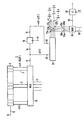
- the figure shows a digital delay device 1 for a single ultrasound reception channel K of a phased array device which is used in the medical field.
- the delay device 1 comprises a shift register 3.
- the shift register 3 has an input 5 and a number z of outputs 7.
- the z outputs 7 of the shift register 3 are connected to the z inputs of a first multiplexer 9.
- the multiplexer 9 also has a control input 11 and an output 13. Depending on a control signal at the control input 11, one of the outputs 7 of the shift register 3 is switched through to the output 13 of the first multiplexer 9.
- the register 15 also has an input 17 for a clock signal and an output 19.
- An ultrasound signal x (t) located at the input 14 of the register 15 is written into the register 15 with the next cycle.
- the ultrasonic signal x (t - ⁇ ) is then present at the output 19 of the register 15, where ⁇ is the time difference between two clock cycles.
- the subsequent ultrasonic signal y (t) which is switched through from the shift register 3 via the first multiplexer 9, is present at the input 14 of the register 15.
- the output 13 of the first multiplexer 9 is also connected to a first input 21 of an interpolator 23.
- the output 19 of the register 15 is connected to a second input 25 of the interpolator 23.
- the interpolator 23 has four outputs 27a to 27d, at each of which a different mixture of the two ultrasonic signals y (t) and x (t-Ar) located at the two inputs 21, 25 of the interpolator 23 can be tapped.
- Other mathematical interpolations can be used as well.
- the outputs 27a to 27d of the interpolator 23 are each connected to an input 29a to 29d of a second multiplexer 31.
- the second multiplexer 31 has a second control input 33 and a second output 35.
- the output 35 of the second multiplexer 31 is, for example, passed to a multiplier 37 for further data processing, which will be explained in more detail later. Multiplication by a factor C is carried out here.
- the method for delaying an ultrasound signal which is reflected from an interface inside a body and was recorded with a phased array applicator, proceeds as follows.
- This ultrasonic signal x (t) arrives at the input 5 of the shift register 3.
- This ultrasound signal x (t) is, for example, the echo of a transmission signal which has a center frequency of e.g. B. 4 MHz was sent.
- a clock frequency of 20 MHz is used to detect the curve shape of the echo signal.
- the time ⁇ between two clocks is 50 nsec.
- This sampling frequency is also used to continue clocking the digital components, that is to say the shift register 3 of the first multiplexer 9, the register 15, the interpolator 23 and the second multiplexer 31.
- the present method and the delay device proceed differently.
- the delay value rounded down to nx AT is applied to the output 13 of the first multiplexer 9 via the first multiplexer 9.
- this is a delay of 200 nsec; So the fourth tap of the shift register 3 is tapped.
- a corresponding control signal is fed from a central control device (not shown) to the first multiplexer 9 via the control input 11.
- the following ultrasound signals are present at the four outputs 27a to 27d of the interpolator 23: At the output 27a, the ultrasound signal x; the ultrasonic signal at output 27b ; the ultrasonic signal at output 27c and the ultrasound signal at the output 27d One cycle away, the value at output 27a would be y, at output 27b same at exit 27c and the same at exit 27d where z is the ultrasound signal following the ultrasound signal y in the next cycle.
- the ultrasound signal x is delayed by 250 nsec; the ultrasonic signal y located at the input 14 of the register 15 is only delayed by the value 200 nsec. What is desired, however, is the value of an ultrasound signal which, for. B. is delayed by a delay value of 235 nsec.
- the four values of the ultrasound signal at the outputs 27a to 27d are continuously transferred to the ultrasound value y due to the interpolation. This means that the ultrasound signal at output 27a applies to a delay of 250 nsec, the ultrasound signal at output 27b applies to a delay by 237.5 nsec, the ultrasound signal at output 27c applies to a delay by 225 nsec, and the ultrasound signal at output 27d applies to a delay of 212.5 nsec.
- output 27b with the closest value 237.5 nsec is to be switched through via second multiplexer 31 to output 35 of second multiplexer 31 for further data processing.
- There is only an error of 2.5 ns (instead of 15 ns without interpolation). It is thus determined interpolatorily what value the ultrasound image signal could have had had a delay in the receiver of 235 nsec. A more precise determination of the value was not possible due to the clock frequency, which corresponds to a time difference of 50 nsec.
- the method explained above for a single ultrasound channel K can be applied to all channels or only a part of the channels of an ultrasound device.
- the ultrasound signal switched through at the output 35 of the second multiplexer 31 is further processed as if it were directly at the output of the first multiplexer 9 according to a conventional method.
- the time shift by a clock length ⁇ has no negative influence on the image quality.
- a further processing that can easily be connected in a digital process is the multiplication of the ultrasound signal by a constant.
- This aperture assignment reduces the side lobe amplitudes relative to the main lobe of the antenna, thus reducing ambiguities in the antenna directional diagram.
- constant propagation medium e.g. water
- this aperture assignment is symmetrical to the center of the array. This symmetry goes at large swivel angles and above all through the echo attenuation of the non-homogeneous propagation medium, e.g. B. lost in human tissue.
- this system-related “weighting” can be compensated for within certain limits.
- the amplitude changes in the delay channels caused by the interpolation or the phase position of the sampling can also be compensated for within certain limits by multiplication by a constant C.
- the multiplier 37 is also advantageous because for each delay channel K each date of the AD value range can be set dynamically and statically. Switching off individual channels or all channels K of the ultrasound device is also possible in this way.
- the advantage of the method and the delay device is a high accuracy of the time delay (in the example of the embodiment, an accuracy of ⁇ 6.25 nsec) with a relatively low sampling frequency of 20 MHz.
- the ratio of sampling frequency to time resolution is therefore significantly improved compared to measures without interpolation.
- very long delay times of up to 20 microseconds and more are also conceivable.
- the time resolution can be made even finer and depends on the effort that is still acceptable during the interpolation.
- an interpolator 23 with eight outputs 27a to 27h is also possible. Interpolation forms other than linear can also be used.
Landscapes
- Engineering & Computer Science (AREA)
- Physics & Mathematics (AREA)
- Radar, Positioning & Navigation (AREA)
- Remote Sensing (AREA)
- Computer Networks & Wireless Communication (AREA)
- General Physics & Mathematics (AREA)
- Acoustics & Sound (AREA)
- Ultra Sonic Daignosis Equipment (AREA)
- Investigating Or Analyzing Materials By The Use Of Ultrasonic Waves (AREA)
Claims (7)
Applications Claiming Priority (2)
| Application Number | Priority Date | Filing Date | Title |
|---|---|---|---|
| DE3616498 | 1986-05-16 | ||
| DE19863616498 DE3616498A1 (de) | 1986-05-16 | 1986-05-16 | Verfahren und vorrichtung zur digitalen verzoegerung von ultraschallsignalen im empfangsfall |
Publications (2)
| Publication Number | Publication Date |
|---|---|
| EP0245740A1 EP0245740A1 (fr) | 1987-11-19 |
| EP0245740B1 true EP0245740B1 (fr) | 1990-11-28 |
Family
ID=6300961
Family Applications (1)
| Application Number | Title | Priority Date | Filing Date |
|---|---|---|---|
| EP87106410A Expired - Lifetime EP0245740B1 (fr) | 1986-05-16 | 1987-05-04 | Procédé et moyen pour le retard numérique de signaux ultrasonores à la réception |
Country Status (4)
| Country | Link |
|---|---|
| US (1) | US4787392A (fr) |
| EP (1) | EP0245740B1 (fr) |
| JP (1) | JPH0679606B2 (fr) |
| DE (2) | DE3616498A1 (fr) |
Families Citing this family (30)
| Publication number | Priority date | Publication date | Assignee | Title |
|---|---|---|---|---|
| FR2628265B1 (fr) * | 1987-03-06 | 1990-12-21 | Thomson Csf | Antenne directive a transducteurs multiples notamment pour sonar |
| FR2652654A1 (fr) * | 1989-09-29 | 1991-04-05 | Philips Electronique Lab | Echographe ultrasonore utilisant un dispositif numerique de formation de voies en reception. |
| JPH084588B2 (ja) * | 1991-07-02 | 1996-01-24 | 富士通株式会社 | 超音波受信装置 |
| US5490511A (en) * | 1992-01-14 | 1996-02-13 | Ge Yokogawa Medical Systems, Ltd | Digital phase shifting apparatus |
| US5269307A (en) * | 1992-01-31 | 1993-12-14 | Tetrad Corporation | Medical ultrasonic imaging system with dynamic focusing |
| GB2301892B (en) * | 1992-07-14 | 1997-02-26 | Intravascular Res Ltd | Methods and apparatus for the examination and treatment of internal organs |
| US5453575A (en) | 1993-02-01 | 1995-09-26 | Endosonics Corporation | Apparatus and method for detecting blood flow in intravascular ultrasonic imaging |
| US5345426A (en) * | 1993-05-12 | 1994-09-06 | Hewlett-Packard Company | Delay interpolator for digital phased array ultrasound beamformers |
| US5501219A (en) * | 1993-09-30 | 1996-03-26 | Siemens Medical Systems, Inc. | Real-time dynamic time-of-flight calculator |
| US6029116A (en) * | 1994-08-05 | 2000-02-22 | Acuson Corporation | Method and apparatus for a baseband processor of a receive beamformer system |
| US5928152A (en) * | 1994-08-05 | 1999-07-27 | Acuson Corporation | Method and apparatus for a baseband processor of a receive beamformer system |
| US5685308A (en) * | 1994-08-05 | 1997-11-11 | Acuson Corporation | Method and apparatus for receive beamformer system |
| US5793701A (en) * | 1995-04-07 | 1998-08-11 | Acuson Corporation | Method and apparatus for coherent image formation |
| GB2293240B (en) * | 1994-09-15 | 1998-05-20 | Intravascular Res Ltd | Ultrasonic visualisation method and apparatus |
| US5964709A (en) * | 1995-06-29 | 1999-10-12 | Teratech Corporation | Portable ultrasound imaging system |
| US5957846A (en) * | 1995-06-29 | 1999-09-28 | Teratech Corporation | Portable ultrasound imaging system |
| US5590658A (en) * | 1995-06-29 | 1997-01-07 | Teratech Corporation | Portable ultrasound imaging system |
| US8241217B2 (en) | 1995-06-29 | 2012-08-14 | Teratech Corporation | Portable ultrasound imaging data |
| US7500952B1 (en) | 1995-06-29 | 2009-03-10 | Teratech Corporation | Portable ultrasound imaging system |
| US6254542B1 (en) | 1995-07-17 | 2001-07-03 | Intravascular Research Limited | Ultrasonic visualization method and apparatus |
| US5784336A (en) * | 1996-11-18 | 1998-07-21 | Furuno Diagnostics America, Inc. | Delay scheme and apparatus for focussing the transmission and reception of a summed ultrasonic beam |
| DE19811346A1 (de) * | 1998-03-16 | 1999-09-30 | Siemens Ag | Verfahren zur Verarbeitung von Signalen |
| DE10028603C1 (de) * | 2000-06-09 | 2001-12-13 | Texas Instruments Deutschland | Schaltungsanordnung zur Erzeugung eines Ausgangs-Phasensignals mit einer bezüglich einer Referenzphase beliebig veränderlichen Phasenverschiebung |
| US7527592B2 (en) * | 2003-11-21 | 2009-05-05 | General Electric Company | Ultrasound probe sub-aperture processing |
| US20050113698A1 (en) * | 2003-11-21 | 2005-05-26 | Kjell Kristoffersen | Ultrasound probe transceiver circuitry |
| US7527591B2 (en) * | 2003-11-21 | 2009-05-05 | General Electric Company | Ultrasound probe distributed beamformer |
| GB0513253D0 (en) * | 2005-06-29 | 2005-08-03 | Oceanscan Ltd | Improved acoustic sensor and method |
| US20100228130A1 (en) * | 2009-03-09 | 2010-09-09 | Teratech Corporation | Portable ultrasound imaging system |
| JP5635540B2 (ja) | 2011-10-26 | 2014-12-03 | ジーイー・メディカル・システムズ・グローバル・テクノロジー・カンパニー・エルエルシー | 受信回路、超音波プローブ及び超音波画像表示装置 |
| US10405829B2 (en) | 2014-12-01 | 2019-09-10 | Clarius Mobile Health Corp. | Ultrasound machine having scalable receive beamformer architecture comprising multiple beamformers with common coefficient generator and related methods |
Family Cites Families (12)
| Publication number | Priority date | Publication date | Assignee | Title |
|---|---|---|---|---|
| US3859622A (en) * | 1973-01-15 | 1975-01-07 | Gen Electric | Electronic scanning switch for sonar |
| JPS522590A (en) * | 1975-06-24 | 1977-01-10 | Toshiba Corp | Supersonic wave emitting and receiving device |
| US4080838A (en) * | 1975-11-12 | 1978-03-28 | Hitachi Medical Corporation | Method and apparatus for controlling ultrasonic waves |
| JPS52107184A (en) * | 1976-03-05 | 1977-09-08 | Hitachi Medical Corp | Device for controlling ultrasonic diagnosis image |
| US4060792A (en) * | 1976-06-17 | 1977-11-29 | Raytheon Company | Hard clipped beam former |
| US4127034A (en) * | 1977-12-23 | 1978-11-28 | General Electric Company | Digital rectilinear ultrasonic imaging system |
| JPS5499379A (en) * | 1978-01-23 | 1979-08-06 | Tokyo Shibaura Electric Co | Ultrasonic video device |
| US4488297A (en) * | 1982-04-05 | 1984-12-11 | Fairchild Camera And Instrument Corp. | Programmable deskewing of automatic test equipment |
| FR2542884B1 (fr) * | 1983-03-18 | 1986-12-26 | Cgr Ultrasonic | Procede d'imagerie par ultrasons a partir d'un alignement d'elements transducteurs |
| EP0150452B1 (fr) * | 1984-01-30 | 1990-01-17 | Kontron Instruments Holding N.V. | Montage émetteur-récepteur pour un appareil d'imagerie à ultrasons |
| JPS60229521A (ja) * | 1984-04-27 | 1985-11-14 | Sony Tektronix Corp | デジタル信号遅延回路 |
| US4700573A (en) * | 1986-03-07 | 1987-10-20 | Hewlett-Packard Company | Method to improve accuracy in delay lines |
-
1986
- 1986-05-16 DE DE19863616498 patent/DE3616498A1/de not_active Withdrawn
-
1987
- 1987-05-04 DE DE8787106410T patent/DE3766412D1/de not_active Expired - Lifetime
- 1987-05-04 EP EP87106410A patent/EP0245740B1/fr not_active Expired - Lifetime
- 1987-05-06 US US07/046,512 patent/US4787392A/en not_active Expired - Lifetime
- 1987-05-15 JP JP62118710A patent/JPH0679606B2/ja not_active Expired - Lifetime
Also Published As
| Publication number | Publication date |
|---|---|
| JPS62280650A (ja) | 1987-12-05 |
| US4787392A (en) | 1988-11-29 |
| EP0245740A1 (fr) | 1987-11-19 |
| DE3616498A1 (de) | 1987-11-19 |
| JPH0679606B2 (ja) | 1994-10-12 |
| DE3766412D1 (de) | 1991-01-10 |
Similar Documents
| Publication | Publication Date | Title |
|---|---|---|
| EP0245740B1 (fr) | Procédé et moyen pour le retard numérique de signaux ultrasonores à la réception | |
| DE3742550C2 (fr) | ||
| DE69117709T2 (de) | Ultraschallabbildungssystem | |
| DE19524505C2 (de) | Verfahren und Vorrichtung zur digitalen Strahlformung | |
| DE3689143T2 (de) | Ultraschallabbildungssystem mit einer dynamisch fokussierten phasengesteuerten linearen Wandleranordnung. | |
| DE3885248T2 (de) | Bildung eines kohärenten Bündels. | |
| DE4409587C2 (de) | Ultraschallabbildungssystem | |
| DE69403897T2 (de) | Digitaler strahlformer mit mehrphasen-parallelverarbeitung | |
| DE19756024A1 (de) | Verfahren und Einrichtung zur Schaffung dynamisch veränderlicher Zeitverzögerungen für einen Ultraschall-Strahlformer | |
| DE19581713B4 (de) | Basisbandprozessor eines Empfangsstrahlformersystems | |
| DE19581716B4 (de) | Verfahren und Einrichtung für ein Doppler-Empfangs-Strahlformersystem | |
| DE69128919T2 (de) | Ultraschallabbildung mit radialer Abtastung eines trapezförmigen Sektors | |
| DE69923748T2 (de) | Verfahren und Vorrichtung zur Ultraschall- Bilddatenerfassung mit Erhöhung der Bildfrequenz und Bildauflösung | |
| DE69106049T2 (de) | Ultraschallbildgerät mit adaptiver Phasenaberrationskorrektur. | |
| DE69535537T2 (de) | Verfahren und vorrichtung zum digitalen mehrkanalempfang und zur diagnose mittels ultraschall | |
| DE3043047C2 (de) | Verfahren und Vorrichtung zur Ultraschallabbildung mit radialen Abtaststrahlen, mit einem hinter einer linearen Transduktoranordnung liegenden hypothetischen Ausgangspunkt | |
| DE3831537A1 (de) | Verfahren und anordnung zum adaptiven reduzieren von phasenaberrationsauswirkungen | |
| DE19756686A1 (de) | Verfahren und Einrichtung zur komplexen Bandpassfilterung und Dezimierung in einem Ultraschall-Strahlbündelformer | |
| DE3003967A1 (de) | Ultraschallabbildungssystem | |
| DE10050366A1 (de) | Numerische Optimierung einer Ultraschallstrahlbahn | |
| DE19850505A1 (de) | Verfahren und Einrichtung für eine adaptive B-Mode Bildverbesserung | |
| DE69223158T2 (de) | Empfangsstrahlformer für eine ultraschall-diagnose-vorrichtung | |
| DE102006013232A1 (de) | Mehrstufiges Strahlenformen | |
| DE69011261T2 (de) | Ultraschall-Echograph mit digitaler Einrichtung zur Formung des Strahlenbündels im Empfangsfall. | |
| DE3634504A1 (de) | Ultraschall-bildvorrichtung |
Legal Events
| Date | Code | Title | Description |
|---|---|---|---|
| PUAI | Public reference made under article 153(3) epc to a published international application that has entered the european phase |
Free format text: ORIGINAL CODE: 0009012 |
|
| AK | Designated contracting states |
Kind code of ref document: A1 Designated state(s): DE FR GB NL |
|
| 17P | Request for examination filed |
Effective date: 19871218 |
|
| 17Q | First examination report despatched |
Effective date: 19890921 |
|
| GRAA | (expected) grant |
Free format text: ORIGINAL CODE: 0009210 |
|
| AK | Designated contracting states |
Kind code of ref document: B1 Designated state(s): DE FR GB NL |
|
| GBT | Gb: translation of ep patent filed (gb section 77(6)(a)/1977) | ||
| REF | Corresponds to: |
Ref document number: 3766412 Country of ref document: DE Date of ref document: 19910110 |
|
| ET | Fr: translation filed | ||
| PLBE | No opposition filed within time limit |
Free format text: ORIGINAL CODE: 0009261 |
|
| STAA | Information on the status of an ep patent application or granted ep patent |
Free format text: STATUS: NO OPPOSITION FILED WITHIN TIME LIMIT |
|
| 26N | No opposition filed | ||
| PGFP | Annual fee paid to national office [announced via postgrant information from national office to epo] |
Ref country code: FR Payment date: 19950522 Year of fee payment: 9 |
|
| PGFP | Annual fee paid to national office [announced via postgrant information from national office to epo] |
Ref country code: NL Payment date: 19950531 Year of fee payment: 9 |
|
| PGFP | Annual fee paid to national office [announced via postgrant information from national office to epo] |
Ref country code: GB Payment date: 19960419 Year of fee payment: 10 |
|
| PG25 | Lapsed in a contracting state [announced via postgrant information from national office to epo] |
Ref country code: NL Effective date: 19961201 |
|
| PG25 | Lapsed in a contracting state [announced via postgrant information from national office to epo] |
Ref country code: FR Effective date: 19970131 |
|
| NLV4 | Nl: lapsed or anulled due to non-payment of the annual fee |
Effective date: 19961201 |
|
| REG | Reference to a national code |
Ref country code: FR Ref legal event code: ST |
|
| PG25 | Lapsed in a contracting state [announced via postgrant information from national office to epo] |
Ref country code: GB Effective date: 19970504 |
|
| GBPC | Gb: european patent ceased through non-payment of renewal fee |
Effective date: 19970504 |
|
| PGFP | Annual fee paid to national office [announced via postgrant information from national office to epo] |
Ref country code: DE Payment date: 20060724 Year of fee payment: 20 |