EP0245327B1 - Anlage zum streckrichten und längsteilen von metallbändern - Google Patents
Anlage zum streckrichten und längsteilen von metallbändern Download PDFInfo
- Publication number
- EP0245327B1 EP0245327B1 EP86906332A EP86906332A EP0245327B1 EP 0245327 B1 EP0245327 B1 EP 0245327B1 EP 86906332 A EP86906332 A EP 86906332A EP 86906332 A EP86906332 A EP 86906332A EP 0245327 B1 EP0245327 B1 EP 0245327B1
- Authority
- EP
- European Patent Office
- Prior art keywords
- stretch
- strip
- slitting
- flattening
- metal strip
- Prior art date
- Legal status (The legal status is an assumption and is not a legal conclusion. Google has not performed a legal analysis and makes no representation as to the accuracy of the status listed.)
- Expired - Lifetime
Links
- 239000002184 metal Substances 0.000 title claims abstract description 8
- 238000009434 installation Methods 0.000 title abstract 2
- 238000000034 method Methods 0.000 claims description 6
- 230000000712 assembly Effects 0.000 abstract 2
- 238000000429 assembly Methods 0.000 abstract 2
- 238000007796 conventional method Methods 0.000 description 2
- 238000011982 device technology Methods 0.000 description 2
- 238000004804 winding Methods 0.000 description 2
- 238000005452 bending Methods 0.000 description 1
- 238000005520 cutting process Methods 0.000 description 1
- 238000004519 manufacturing process Methods 0.000 description 1
Images
Classifications
-
- B—PERFORMING OPERATIONS; TRANSPORTING
- B21—MECHANICAL METAL-WORKING WITHOUT ESSENTIALLY REMOVING MATERIAL; PUNCHING METAL
- B21D—WORKING OR PROCESSING OF SHEET METAL OR METAL TUBES, RODS OR PROFILES WITHOUT ESSENTIALLY REMOVING MATERIAL; PUNCHING METAL
- B21D1/00—Straightening, restoring form or removing local distortions of sheet metal or specific articles made therefrom; Stretching sheet metal combined with rolling
- B21D1/05—Stretching combined with rolling
Definitions
- the invention relates to a method for stretch straightening and slitting metal strip, in which the metal strip is held under tension by an inlet-side and an outlet-side tensioning drum group, while it is divided lengthwise into several partial strips in the area between the tensioning drum groups by a slitting shear.
- the invention has for its object to provide a method of the type mentioned that enables the production of flat partial strips with little effort in terms of device technology.
- This object is achieved in that the metal strip in the area of the slitting shear is overstretched by the two tensioning drum groups.
- the partial strips between the slitting shear and the outlet-side tensioning drum group are preferably stretch-oriented.
- each partial strip Since in the invention the longitudinal dividing takes place under stretching and / or before passing through the stretching / straightening apparatus, the tensions of each partial strip are balanced so that each partial strip is flat.
- the stretch straightening or stretch bending straightening between the two tensioning drum groups which takes place when the belt is overstretched, also achieves a length compensation between the individual partial strips, because each partial strip is treated individually.
- the shorter partial strips created in conventional methods are stretched more in the method according to the invention than the longer partial strips created in conventional methods. This length compensation facilitates winding on the reel under the same tension.
- the invention is explained in more detail below with the aid of a drawing representing an exemplary embodiment.
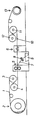
- the drawing shows a schematic side view of the system for stretching and slitting.
- the strip 1 to be stretched and longitudinally divided into partial strips is wound on a reel 2.
- the tape 1 is drawn off from an inlet-side tensioning drum set 3, 4 and passes via a slitting shear 5, which consists of several circular knives arranged next to one another on opposite sides of the sliver 1, to a straightening device 6.
- the seams 7 of the tape separated from the outer slitting knives become chopped into short pieces by a chopper 8 and fed to a scrap collecting container 9.
- the partial strips 10 arrive at a take-up reel 13 via an outlet-side tensioning drum set 11, 12.
- the tape 1 and the partial strips 10 must be under a certain Tension is maintained so that the required tension can be applied from the tensioning drum sets 3, 4, 11, 12 to the belt 1 and the partial strips 10 on the route between the two tensioning drum sets 3, 4, 11, 12.
- plane partial strips 10 are obtained with the least expenditure on device technology.
- the tape 1 is no longer stretch-oriented as before, but the individual partial strips are stretch-oriented. Due to the direct arrangement of the slitting shears 5 in front of the stretching / straightening apparatus, a special guidance of the partial strips 10 is unnecessary. Due to the simultaneous stretching of the parallel partial strips 10, taking into account the individual tension in the individual partial strips 10, they obtain the same length.
Landscapes
- Engineering & Computer Science (AREA)
- Mechanical Engineering (AREA)
- Winding, Rewinding, Material Storage Devices (AREA)
- Straightening Metal Sheet-Like Bodies (AREA)
- Shearing Machines (AREA)
Description
- Die Erfindung bezieht sich auf ein Verfahren zum Streckrichten und Längsteilen von Metallband, bei dem das Metallband von einer einlaufseitigen und einer auslaufseitigen Spanntrommelgruppe unter Spannung gehalten wird, während es im Bereich zwischen den Spanntrommelgruppen von einer Längsteilschere in mehrere Teilstreifen längsgeteilt wird.
- Es ist bekannt, daß kaltgewalzte Bänder ohne Nachbehandlung unkontrolliert verteilte innere Spannungen aufweisen. Aufgrund dieser Spannungen sind die Bänder nicht plan. Um Bänder mit der gewünschten Planheit zu erhalten, werden sie durch Überdehnen zwischen den beiden Spanntrommelgruppen streckgerichtet. Bei dickeren Bändern kann zum Überdehnen ein Streckrichtapparat zwischen den beiden Spanntrommelgruppen angeordnet sein.
- Es ist auch bekannt, die planen Bänder nach dem Streckrichten in Teilstreifen zu unterteilen und diese Teilstreifen auf einer Haspel aufzuwickeln. Beim Längsteilen entstehen jedoch neue Spannungen in den Teilstreifen, die die Ursache von neuen Unebenheiten in den Teilstreifen sind. Um plane Teilstreifen zu erhalten, müssen diese deshalb nach dem Längsteilen in einem weiteren Arbeitsgang einzeln gerichtet werden. Diese Arbeitsweise ist aufwendig.
- Schließlich ist ein Verfahren der eingangs genannten Art bekannt (US-A-3 416 347). Bei diesem Stand der Technik erfolgt das Trennen des Bandes in Teilstreifen in zwei Stufen, und zwar werden in der ersten Stufe nur Rillen in das Band eingeprägt, und in der zweiten Stufe das Band im Bereich der Rillen durchtrennt. Nach diesem Durchtrennen und vor dem Aufhaspeln ist ein Streckrichtapparat vorgesehen. Ob auf diese Art und Weise alle inneren Spannungen und beim Trennen zusätzlich eingebrachte Spannungen, die zu einer Verwerfung der Teitstreifen führen, beseitigt werden, um das Band problemlos aufwickeln zu können, ist fraglich.
- Der Erfindung liegt die Aufgabe zugrunde, ein Verfahren der eingangs genannten Art zu schaffen, das mit geringem vorrichtungstechnischen Aufwand die Herstellung planer Teilstreifen ermöglicht.
- Diese Aufgabe wird erfindungsgemäß dadurch gelöst, daß das Metallband im Bereich der Längsteilschere von den beiden Spanntrommelgruppen überdehnt wird. Vorzugsweise werden die Teilstreifen zwischen der Längsteilschere und der auslaufseitigen Spanntrommelgruppe streckgerichtet.
- Da bei der Erfindung das Längsteilen unter Streckzug und/oder vor dem Durchlauf durch den Streckrichtapparat erfolgt, werden die Spannungen eines jeden Teilstreifens ausgeglichen, so daß jeder Teilstreifen plan ist. Durch das Streckrichten oder Streckbiegerichten zwischen den beiden Spanntrommelgruppen, das unter einer Überdehnung des Bandes erfolgt, wird darüber hinaus ein Längenausgleich zwischen den einzelnen Teilstreifen erzielt, denn jeder Teil streifen wird individuell behandelt. Die bei herkömmlichen Verfahren entstehenden kürzeren Teilstreifen werden bei dem erfindungsgemäßen Verfahren stärker gedehnt als die bei herkömmlichen Verfahren entstehenden längeren Teilstreifen. Dieser Längenausgleich erleichtert das Aufwickeln auf der Aufwickelhaspel unter gleicher Zugspannung.
- Im folgenden wird die Erfindung anhand einer ein Ausführungsbeispiel darstellenden Zeichnung näher erläutert. Die Zeichnung zeigt in Seitenansicht schematisch die Anlage zum Streckrichten und Längsteilen.
- Das streckzurichtende und in Teilstreifen längszuteilende Band 1 ist auf einer Haspel 2 aufgewikkelt. Von einem einlaufseitigen Spanntrommelsatz 3, 4 wird das Band 1 abgezogen und gelangt über eine Längsteilschere 5, die aus mehreren, auf gegenüberliegenden Seiten des Bandes 1 nebeneinander angeordneten Kreismessern besteht, zu einem Richtapparat 6. Die von den äußeren Längsteilmessern abgetrennten Säume 7 des Bandes werden von einem Zerhacker 8 in kurze Stücke zerhackt und einem Schrottsammelbehälter 9 zugeführt. Die Teilstreifen 10 gelangen über einen auslaufseitigen Spanntrommelsatz 11, 12 zu einer Aufwickelhaspel 13. Zwischen derAbwickelhaspel 2 und dem einlaufseitigen Spanntrommelsatz 3,4 einerseits und dem auslaufseitigen Spanntrommelsatz 11, 12 und der Aufwickelhaspel 13 andererseits müssen das Band 1 und die Teilstreifen 10 unter einer gewissen Spannung gehalten werden, damit von den Spanntrommelsätzen 3, 4, 11, 12 auf das Band 1 und die Teilstreifen 10 auf der Strecke zwischen den beiden Spanntrommelsätzen 3, 4, 11, 12 die erforderliche Zugspannung aufgebracht werden kann.
- Die besonderen Vorteile der Erfindung bestehen darin, daß bei geringstem vorrichtungstechnischen Aufwand plane Teilstreifen 10 erhalten werden. Nicht mehr wie bisher wird das Band 1 streckgerichtet, sondern es werden die einzelnen Teilstreifen streckgerichtet. Durch die unmittelbare Anordnung der Längsteilschere 5 vor dem Streckrichtapparat erübrigt sich eine besondere Führung der Teilstreifen 10. Durch das gleichzeitige Streckrichten der parallel geführten Teilstreifen 10 erhalten unter Berücksichtigung der individuellen Spannung in den einzelnen Teilstreifen 10 diese die gleiche Länge.
Claims (2)
dadurch gekennzeichnet, daß das Metallband (1) im Bereich der Längsteilschere (5) von den beiden Spanntrommelgruppen (3,4; 11,12) überdehnt wird.
dadurch gekennzeichnet, daß die Teilstreifen (10) zwischen der Längsteilschere (5) und der auslaufseitigen Spanntrommelgruppe (11, 12) streckgerichtet werden.
Priority Applications (1)
| Application Number | Priority Date | Filing Date | Title |
|---|---|---|---|
| AT86906332T ATE56164T1 (de) | 1985-11-05 | 1986-11-05 | Anlage zum streckrichten und laengsteilen von metallbaendern. |
Applications Claiming Priority (2)
| Application Number | Priority Date | Filing Date | Title |
|---|---|---|---|
| DE3539153A DE3539153C1 (de) | 1985-11-05 | 1985-11-05 | Anlage zum Streckrichten und Laengsteilen von Metallbaendern |
| DE3539153 | 1985-11-05 |
Publications (2)
| Publication Number | Publication Date |
|---|---|
| EP0245327A1 EP0245327A1 (de) | 1987-11-19 |
| EP0245327B1 true EP0245327B1 (de) | 1990-09-05 |
Family
ID=6285173
Family Applications (1)
| Application Number | Title | Priority Date | Filing Date |
|---|---|---|---|
| EP86906332A Expired - Lifetime EP0245327B1 (de) | 1985-11-05 | 1986-11-05 | Anlage zum streckrichten und längsteilen von metallbändern |
Country Status (5)
| Country | Link |
|---|---|
| US (1) | US4866967A (de) |
| EP (1) | EP0245327B1 (de) |
| JP (1) | JPS63501411A (de) |
| DE (2) | DE3539153C1 (de) |
| WO (1) | WO1987002604A1 (de) |
Families Citing this family (15)
| Publication number | Priority date | Publication date | Assignee | Title |
|---|---|---|---|---|
| AT392747B (de) * | 1989-02-23 | 1991-05-27 | Boehler Gmbh | Verfahren und anordnung zum walzen von draht -oder stabmaterial |
| US5086634A (en) * | 1990-11-26 | 1992-02-11 | Braner, Inc. | Coil-to-coil steel slitting process |
| EP0528154A1 (de) * | 1991-07-31 | 1993-02-24 | DANIELI & C. OFFICINE MECCANICHE S.p.A. | Verfahren und Vorrichtung zum Herstellen einzelner Fertigprofile aus kalten Mehrprofilelementen |
| US6857350B1 (en) * | 1999-07-22 | 2005-02-22 | Red Bud Industries, Inc. | Appliance and process for reducing distortion of slit metal sheet |
| US20070074556A1 (en) * | 2005-10-04 | 2007-04-05 | Shape Corporation | Continuous process of roll-forming stamped sheet |
| PL2220320T3 (pl) | 2007-11-13 | 2020-01-31 | Guardian Glass, LLC | Pakiet szyb zespolonych i element dystansowy |
| US9309714B2 (en) | 2007-11-13 | 2016-04-12 | Guardian Ig, Llc | Rotating spacer applicator for window assembly |
| EP2454437B1 (de) | 2009-07-14 | 2017-05-10 | Guardian IG, LLC | Gedehnte streifen für distanzstück und abgedichtete einheit |
| EP2580418B1 (de) | 2010-06-10 | 2014-08-13 | Guardian IG, LLC | Fensterabstandhalteraufträger |
| US9228389B2 (en) | 2010-12-17 | 2016-01-05 | Guardian Ig, Llc | Triple pane window spacer, window assembly and methods for manufacturing same |
| CN103128357A (zh) * | 2011-12-02 | 2013-06-05 | 中国有色金属工业第六冶金建设有限公司 | 铝软带自动送料矫直剪切装置 |
| US9689196B2 (en) | 2012-10-22 | 2017-06-27 | Guardian Ig, Llc | Assembly equipment line and method for windows |
| US9260907B2 (en) | 2012-10-22 | 2016-02-16 | Guardian Ig, Llc | Triple pane window spacer having a sunken intermediate pane |
| JP6850418B2 (ja) * | 2017-02-08 | 2021-03-31 | 日立金属株式会社 | 金属条の製造方法 |
| US12447519B2 (en) * | 2020-12-17 | 2025-10-21 | Allor Manufacturing, Llc | Device and method for leveling a metal plate |
Family Cites Families (8)
| Publication number | Priority date | Publication date | Assignee | Title |
|---|---|---|---|---|
| DE33065C (de) * | L. VON WAGNER, Professor, und A. GlLLITZER in Budapest | Neuerung an einem Siebapparate zur Stärkefabrikation | ||
| GB465564A (en) * | 1936-10-12 | 1937-05-10 | Gunnar Hjalmar Lager | Improvements in machines for shearing metal and other sheet material |
| US3338208A (en) * | 1965-09-07 | 1967-08-29 | Paul U Voss | Continuous equipment for pickling and slitting strip steel |
| US3416347A (en) * | 1965-10-29 | 1968-12-17 | Yoder Co | Slitting and edge conditioning means |
| DE3001230C2 (de) * | 1980-01-15 | 1981-12-17 | Sundwiger Eisenhütte Maschinenfabrik Grah & Co, 5870 Hemer | Verfahren zum Spalten eines Bandes und Spaltanlage für Bänder |
| US4347723A (en) * | 1980-08-22 | 1982-09-07 | The Monarch Machine Tool Company | Method and apparatus for tensioning metallic strips on a slitting line |
| US4614101A (en) * | 1981-12-01 | 1986-09-30 | Herr-Voss Corporation | Method of rewinding slit metal strands |
| DE3203581A1 (de) * | 1982-02-03 | 1983-08-11 | Bwg Bergwerk- Und Walzwerk-Maschinenbau Gmbh, 4100 Duisburg | Verfahren und vorrichtung zum herstellen von metallband aus warmband, insbesondere warmbreitband |
-
1985
- 1985-11-05 DE DE3539153A patent/DE3539153C1/de not_active Expired
-
1986
- 1986-11-05 EP EP86906332A patent/EP0245327B1/de not_active Expired - Lifetime
- 1986-11-05 DE DE8686906332T patent/DE3673997D1/de not_active Expired - Lifetime
- 1986-11-05 WO PCT/EP1986/000635 patent/WO1987002604A1/de not_active Ceased
- 1986-11-05 JP JP61505804A patent/JPS63501411A/ja active Pending
-
1988
- 1988-11-17 US US07/273,715 patent/US4866967A/en not_active Expired - Fee Related
Also Published As
| Publication number | Publication date |
|---|---|
| DE3539153C1 (de) | 1986-07-17 |
| US4866967A (en) | 1989-09-19 |
| WO1987002604A1 (fr) | 1987-05-07 |
| EP0245327A1 (de) | 1987-11-19 |
| JPS63501411A (ja) | 1988-06-02 |
| DE3673997D1 (de) | 1990-10-11 |
Similar Documents
| Publication | Publication Date | Title |
|---|---|---|
| EP0245327B1 (de) | Anlage zum streckrichten und längsteilen von metallbändern | |
| DE2950473C2 (de) | ||
| DE19905286A1 (de) | Arbeitsverfahren und Anlage zum flexiblen und wirtschaftlichen Beizen und Kaltwalzen von Metallbändern | |
| EP2119514A1 (de) | Verfahren und Vorrichtung zum Richten eines Metallbandes | |
| DE2537188A1 (de) | Verfahren und warmbandstrasse zur verbesserung der qualitaetseigenschaften von warmband | |
| DE69330683T2 (de) | Verfahren zum Entzundern und Kaltwalzen von Metallband | |
| DE69429880T2 (de) | Planiergruppe in blechband streckrichtmaschinen mit arbeitsrollen von zunehmendem durchmesser | |
| DE3203581C2 (de) | ||
| DE69204545T2 (de) | Verfahren zur Herstellung von Profilen und/oder Stäben im kalten Zustand. | |
| DE2327657A1 (de) | Verfahren zum kontinuierlichen herstellen von geschweissten leichtbautraegerprofilen, insbesondere i- oder ttraegern | |
| EP2464473A1 (de) | Verfahren zum vieladrigen entgraten von drahtadern und zugehörige vorrichtung | |
| DE1140891B (de) | Verfahren zum Richten von Metallband | |
| DE1299587B (de) | Vorwalzstrasse fuer ó±-Profiltraeger | |
| CH435183A (de) | Verfahren und Vorrichtung zur Herstellung profilierter, geschweisster Längsträger, sowie nach dem Verfahren hergestellter Stahlleichtträger | |
| DE4445716C2 (de) | Verfahren und Fertigungslinie zum Herstellen von kaltgewaltzem, nicht rostendem Stahlband | |
| DE2623995C3 (de) | Thermisch getrenntes Profil sowie Verfahren und Anlage zu seiner Herstellung | |
| DE3919836A1 (de) | Verfahren und anlage zum coupieren der anfangswindungen und/oder endwindungen eines drahtbundes | |
| DE4124800C2 (de) | Verfahren zum Behandeln von Metallbändern | |
| DE69300944T2 (de) | Verfahren und Vorrichtung zum Herstellen von einzelnen runden Stangen im warmen Zustand aus warmen Mehrfachelementen. | |
| DE1452956A1 (de) | Fertigungsanlage fuer aus einem Steg,einem Ober- und/oder einem Untergurt zusammengeschweisste Stahlleichtbautraeger unter Verwendung von bandfoermigem Ausgangsmaterial | |
| DE747855C (de) | Bandkaltwalzwerk | |
| DE3513831C2 (de) | ||
| DE69003242T2 (de) | Verfahren zum richten von bändern durch strecken und biegen. | |
| CH358773A (de) | Verfahren und Vorrichtung zur Herstellung von metallenen längsgewellten Bändern | |
| DE833776C (de) | Verfahren zum Herstellen von Werkstuecken aus bewehrtem Beton od. dgl. |
Legal Events
| Date | Code | Title | Description |
|---|---|---|---|
| PUAI | Public reference made under article 153(3) epc to a published international application that has entered the european phase |
Free format text: ORIGINAL CODE: 0009012 |
|
| 17P | Request for examination filed |
Effective date: 19870626 |
|
| AK | Designated contracting states |
Kind code of ref document: A1 Designated state(s): AT BE CH DE FR GB IT LI LU NL SE |
|
| 17Q | First examination report despatched |
Effective date: 19890110 |
|
| GRAA | (expected) grant |
Free format text: ORIGINAL CODE: 0009210 |
|
| AK | Designated contracting states |
Kind code of ref document: B1 Designated state(s): AT BE CH DE FR GB IT LI LU NL SE |
|
| REF | Corresponds to: |
Ref document number: 56164 Country of ref document: AT Date of ref document: 19900915 Kind code of ref document: T |
|
| ET | Fr: translation filed | ||
| GBT | Gb: translation of ep patent filed (gb section 77(6)(a)/1977) | ||
| REF | Corresponds to: |
Ref document number: 3673997 Country of ref document: DE Date of ref document: 19901011 |
|
| ITF | It: translation for a ep patent filed | ||
| PG25 | Lapsed in a contracting state [announced via postgrant information from national office to epo] |
Ref country code: LI Free format text: LAPSE BECAUSE OF NON-PAYMENT OF DUE FEES Effective date: 19901130 Ref country code: CH Free format text: LAPSE BECAUSE OF NON-PAYMENT OF DUE FEES Effective date: 19901130 |
|
| RAP2 | Party data changed (patent owner data changed or rights of a patent transferred) |
Owner name: SUNDWIGER EISENHUETTE MASCHINENFABRIK GMBH & CO. |
|
| PLBI | Opposition filed |
Free format text: ORIGINAL CODE: 0009260 |
|
| REG | Reference to a national code |
Ref country code: CH Ref legal event code: PL |
|
| NLT2 | Nl: modifications (of names), taken from the european patent patent bulletin |
Owner name: SUNDWIGER EISENHUETTE MASCHINENFABRIK GMBH & CO. T |
|
| 26 | Opposition filed |
Opponent name: MANNESMANN AKTIENGESELLSCHAFT Effective date: 19910604 |
|
| NLR1 | Nl: opposition has been filed with the epo |
Opponent name: MANNESMANN AG. |
|
| ITTA | It: last paid annual fee | ||
| PGFP | Annual fee paid to national office [announced via postgrant information from national office to epo] |
Ref country code: DE Payment date: 19921228 Year of fee payment: 7 |
|
| PGFP | Annual fee paid to national office [announced via postgrant information from national office to epo] |
Ref country code: LU Payment date: 19931015 Year of fee payment: 8 |
|
| PGFP | Annual fee paid to national office [announced via postgrant information from national office to epo] |
Ref country code: FR Payment date: 19931019 Year of fee payment: 8 |
|
| PGFP | Annual fee paid to national office [announced via postgrant information from national office to epo] |
Ref country code: SE Payment date: 19931026 Year of fee payment: 8 |
|
| PGFP | Annual fee paid to national office [announced via postgrant information from national office to epo] |
Ref country code: GB Payment date: 19931027 Year of fee payment: 8 |
|
| PGFP | Annual fee paid to national office [announced via postgrant information from national office to epo] |
Ref country code: BE Payment date: 19931112 Year of fee payment: 8 |
|
| PGFP | Annual fee paid to national office [announced via postgrant information from national office to epo] |
Ref country code: AT Payment date: 19931122 Year of fee payment: 8 |
|
| PGFP | Annual fee paid to national office [announced via postgrant information from national office to epo] |
Ref country code: NL Payment date: 19931130 Year of fee payment: 8 |
|
| EPTA | Lu: last paid annual fee | ||
| RDAC | Information related to revocation of patent modified |
Free format text: ORIGINAL CODE: 0009299REVO |
|
| RDAG | Patent revoked |
Free format text: ORIGINAL CODE: 0009271 |
|
| STAA | Information on the status of an ep patent application or granted ep patent |
Free format text: STATUS: PATENT REVOKED |
|
| 27W | Patent revoked |
Effective date: 19940511 |
|
| GBPR | Gb: patent revoked under art. 102 of the ep convention designating the uk as contracting state |
Free format text: 940511 |
|
| NLR2 | Nl: decision of opposition | ||
| R27W | Patent revoked (corrected) |
Effective date: 19940511 |
|
| EUG | Se: european patent has lapsed |
Ref document number: 86906332.1 Effective date: 19940810 |
|
| APAH | Appeal reference modified |
Free format text: ORIGINAL CODE: EPIDOSCREFNO |