EP0244879B1 - Imprimante pour livrets d'épargne - Google Patents
Imprimante pour livrets d'épargne Download PDFInfo
- Publication number
- EP0244879B1 EP0244879B1 EP87107770A EP87107770A EP0244879B1 EP 0244879 B1 EP0244879 B1 EP 0244879B1 EP 87107770 A EP87107770 A EP 87107770A EP 87107770 A EP87107770 A EP 87107770A EP 0244879 B1 EP0244879 B1 EP 0244879B1
- Authority
- EP
- European Patent Office
- Prior art keywords
- passbook
- printhead
- edge
- document
- mark
- Prior art date
- Legal status (The legal status is an assumption and is not a legal conclusion. Google has not performed a legal analysis and makes no representation as to the accuracy of the status listed.)
- Expired - Lifetime
Links
Images


Classifications
-
- G—PHYSICS
- G06—COMPUTING OR CALCULATING; COUNTING
- G06K—GRAPHICAL DATA READING; PRESENTATION OF DATA; RECORD CARRIERS; HANDLING RECORD CARRIERS
- G06K13/00—Conveying record carriers from one station to another, e.g. from stack to punching mechanism
- G06K13/02—Conveying record carriers from one station to another, e.g. from stack to punching mechanism the record carrier having longitudinal dimension comparable with transverse dimension, e.g. punched card
-
- B—PERFORMING OPERATIONS; TRANSPORTING
- B41—PRINTING; LINING MACHINES; TYPEWRITERS; STAMPS
- B41J—TYPEWRITERS; SELECTIVE PRINTING MECHANISMS, i.e. MECHANISMS PRINTING OTHERWISE THAN FROM A FORME; CORRECTION OF TYPOGRAPHICAL ERRORS
- B41J11/00—Devices or arrangements of selective printing mechanisms, e.g. ink-jet printers or thermal printers, for supporting or handling copy material in sheet or web form
- B41J11/36—Blanking or long feeds; Feeding to a particular line, e.g. by rotation of platen or feed roller
- B41J11/42—Controlling printing material conveyance for accurate alignment of the printing material with the printhead; Print registering
- B41J11/46—Controlling printing material conveyance for accurate alignment of the printing material with the printhead; Print registering by marks or formations on the paper being fed
-
- B—PERFORMING OPERATIONS; TRANSPORTING
- B41—PRINTING; LINING MACHINES; TYPEWRITERS; STAMPS
- B41J—TYPEWRITERS; SELECTIVE PRINTING MECHANISMS, i.e. MECHANISMS PRINTING OTHERWISE THAN FROM A FORME; CORRECTION OF TYPOGRAPHICAL ERRORS
- B41J13/00—Devices or arrangements of selective printing mechanisms, e.g. ink-jet printers or thermal printers, specially adapted for supporting or handling copy material in short lengths, e.g. sheets
- B41J13/26—Registering devices
-
- B—PERFORMING OPERATIONS; TRANSPORTING
- B41—PRINTING; LINING MACHINES; TYPEWRITERS; STAMPS
- B41J—TYPEWRITERS; SELECTIVE PRINTING MECHANISMS, i.e. MECHANISMS PRINTING OTHERWISE THAN FROM A FORME; CORRECTION OF TYPOGRAPHICAL ERRORS
- B41J3/00—Typewriters or selective printing or marking mechanisms characterised by the purpose for which they are constructed
- B41J3/28—Typewriters or selective printing or marking mechanisms characterised by the purpose for which they are constructed for printing downwardly on flat surfaces, e.g. of books, drawings, boxes, envelopes, e.g. flat-bed ink-jet printers
- B41J3/283—Typewriters or selective printing or marking mechanisms characterised by the purpose for which they are constructed for printing downwardly on flat surfaces, e.g. of books, drawings, boxes, envelopes, e.g. flat-bed ink-jet printers on bank books or the like
Definitions
- the present invention relates to a printing apparatus for use as part of a teller terminal in automatic banking equipment for printing a record of a banking transaction on a passbook for the information and retention of the banking customer.
- Modern banking practice includes the use of so-called teller terminals for use by individual bank tellers in communicating with a supervisory data processing system. As well as keyboard and display units, it has become the practice to include in teller terminals a printer for printing customer passbooks.
- the teller opens the passbook at the latest page and indicates on the keypad which line of the passbook is next to be filled in.
- the opened passbook is then inserted into the passbook printer and the supervistory data processing system commands the passbook printer to print details on the open passbook at the indicated line according to information fed to the supervisory data processing system by the teller through his or her keypad.
- US-A 3 951 251 discloses a passbook printer wherein a passbook is opened at the latest page, is inserted into the printer in a predetermined, pre- aligned orientation, and is inducted into the printer for printing on the appropriate line.
- US-A 3 814 227 discloses a matrix of print rods which can be caused to print in any selected orientation when commanded to do so.
- JP-A-58-92 031 discloses means for detecting a page mark or marks on one edge of a bank book which is inserted, in a predetermined orientation, into a printer.
- the present invention consists in a printing system comprising a document and a printer, said document comprising first, second, third and fourth edges; said printer comprising a printhead movable along a path and a scanner operative to detect and to provide indication of which one of said first, second, third or fourth edges is a presented edge aligned parallel with the path of movement of said printhead; where said printhead is coupled to receive said indication from said scanner and is operative in response thereto to select an orientation of printing of characters on said document whereby characters printed on said document are always aligned with a predetermined one of said edges re- gardlessly of which one of said edges is aligned with said path of movement of said printhead.
- a passbook printer having a flat bed comprising a feed tray, a conveyor belt, a printing bed and a raisable barrier.
- An open passbook is placed upon the feed tray with a portion of the passbook resting on the conveyor belt.
- the passbook printer is activated and responds by raising the barrier across the flat bed.
- the barrier is provided in the vicinity of the printing bed.
- the passbook printer then activates the conveyor belt which draws the passbook from the feed tray towards the barrier.
- the passbook collides with the barrier and by sliding engagement with the conveyor belt one of the passbook's edges is aligned with the barrier. After the conveyor belt has been running for a predetermined time, sufficient to achieve the above action, the conveyor belt is switched off and the barrier is lowered out of the plane of the flat bed.
- the passbook printer comprises a transport apparatus consisting in two spaced pairs of drive rollers in the flat bed, together with a set of lowerable clamp rollers. As soon as the barrier is lowered, the passbook printer lowers the clamp rollers onto the passbook to grip the passbook against the drive rollers.
- the drive rollers are advanced by measurable increments, preferably using a stepping motor. All of the drive rollers move in concert from a common drive source. The drive rollers can be used to move the now aligned passbook a selectable distance to and fro on the flat bed.
- a printhead assembly lies behind the barrier and comprises a sensor and a matrix print head on a common belt driven by a common stepping motor transversely to the direction of movement wherein the transport apparatus is operable to move the passbook.
- the sensor is preferably an optical sensor.
- the drive rollers move the passbook forward a predetermined number of steps to lie beneath the printhead assembly.
- the passbook printer moves the sensor and printhead to a start position and thereafter sweeps the sensor across the passbook to detect where its edge begins.
- the printhead is a predetermined number of steps behind the sensor so that the passbook printer knows at all times thereafter where the printhead is relative to the edge of the passbook by means of counting the number of steps imparted to the printhead and sensor assembly.
- the passbook is provided with two kinds of pre-printing.
- the first type of pre-printing is made with thin lines and the second type with thick lines.
- the sensor is moved across the passbook.
- the thin lines keep the optical sensor dark for one or fewer steps.
- the matrix printer's own printing also keeps the reflected light to the sensor dark for one or fewer steps.
- the second kind of pre-printing is in thick, bold type and keeps the light reflected into the sensor dark for four or more steps of the sensor across the passbook. In this way, the sensor can detect the mark.
- the passbook is provided with two dense marks such that one lies at the top and one at the bottom of one of the pages when the passbook is open. Dependent upon whether the sensor detects a mark far removed from the point where it first detects the edge of the passbook or detects a mark close to the point whereat it first detects the edge of the passbook, or detects two marks in its sweep across the passbook or detects no mark at all in its sweep across the passbook, so the sensor is able to detect which of the four possible edges of the passbook has become aligned with the barrier.
- the control characters from the character generator feeding the printhead matrix printer are accordingly swung around to accord with the appropriate direction of presentation of the passbook and the printhead and drive rollers controlled to print the desired row of characters in the passbook regardless of the orientation of the passbook.
- Figure I shows a projected view of the preferred embodiment of the present invention with cover removed.
- the preferred embodiment consists in a base 10 having a top thereof, a flat bed 12 comprising a feed tray 14, a conveyor belt 16 and a printing bed 18.
- the base 10 is normally sunk into a recess on a support table up to a position indicated by a dotted line 20. It is to be understood that the base 10 can be sunk until the feed tray 14 becomes level with the supporting table to provide an extended feed area.
- Clamp roller assemblies 22 are rotatable about clamp rods 24 to form a first part of a passbook transport apparatus.
- the clamp rods 24 are shown by way of example as being rotatable by a solenoid 26 pulling on a bell crank 28 to rotate a first pulley 30 and thereby rotate a second pulley 32 through the medium of a connecting belt 34 for the second pulley 32 to rotate the clamp rod 24.
- a solenoid 26 pulling on a bell crank 28 to rotate a first pulley 30 and thereby rotate a second pulley 32 through the medium of a connecting belt 34 for the second pulley 32 to rotate the clamp rod 24.
- Those skilled in the art will be aware of other means whereby the clamp rods 24 may be rotated.
- only the leading clamp rod 24 nearer to the conveyor belt 16 need be rotatable, the clamp roller assemblies 22 on the transport apparatus remote from the conveyor belt 16 being usable in permanent engagement with their associated drive rollers.
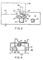
- Figure 2 shows an elevation of the assembly of Figure I with a cover 36 and printhead assembly 38 shown in phantom outline.
- a barrier 40 is raisable between the clamp roller assemblies 22 in the printing bed 18.
- a first drive motor 42 a stepping motor, drives a first toothed belt 44 in common about drive roller pulleys 46 so that all four drive pulleys 46 move in concert.
- a second drive motor 48 drives the conveyor belt 16 and can range in its type from a stepping motor to a simple electical motor.
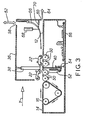
- Figure 3 shows a cross-sectional view of the complete apparatus, the cross-section being taken through that part of the preferred embodiment indicated in Figure I by the line X-X' looking in the direction of the arrows.
- the drive roller pulleys 46 rotate the drive rollers 50 as indicated.
- a bank passbook may be gripped between the clamp roller assembly 22 and its attendant drive rollers 50 to be advanced or withdrawn in the apparatus with precision by the stepping of the first drive motor 42.
- the barrier 40 can be raised by a simple second solenoid 52 returnable by means of a first spring 54.
- the barrier 40 is interposed in the path of a passbook, as will later be described, beneath the printhead assembly 38.
- the preferred embodiment further comprises an electronic assembly 56 whose function in controlling the printhead assembly 38 and the various motors 42, 48 will be later described.
- a passbook introduced on the feed tray 14 onto the conveyor belt 16 may (after printing) either be returned from whence it came back onto the feed tray 14 by reverse action of the transport apparatus consisting in the clamp roller assemblies 22 and the drive rollers 50, together with possible reverse action of conveyor belt 16, or may be directed through one or other of a first rear aperture 58 or a second rear aperture 60 as indicated respectively by a first arrow 62 and a second arrow 64, by means of a deflecting blade 66 which may be raised into an upper position by a third solenoid 68 to allow the passbook to pass through the second rear aperture 60 or which can be, in absence of energisation of the third solenoid 68, be returned by a second spring 70 onto the flat bed 12 to divert the passbook up through the first rear aperture 58.
- a passbook may also be inserted through the first rear aperture 58 to slide down the deflecting blade 66 to engage the transport apparatus 22,50 to be printed by the passbook printer.
- the transport apparatus 22,50 must transport the passbook right on to the conveyor belt 16 for the passbook to be treated thereafter in a conventional manner to be described hereafter.
- Figure 4 shows a view of the printhead assembly 38 of Figures 2 and 3 looking in the direction of the arrow Y in Figure 3.
- the printhead assembly 38 comprises a support yoke 72 for holding cog wheels 74 and stepping motor 76 respectively holding and driving a second toothed belt 78 transversely to the motion of the conveyor belt 16.
- the second toothed belt 78 supports a sensor 80 and a matrix printhead 82.
- the sensor 80 and the matrix printhead 82 are spaced apart by a known number of steps of the stepping motor 76. Thus, if the sensor 80 passes a point, the stepping motor 76 has only to step by the known predetermined number of steps to bring the matrix printhead 82 over the same point.
- the sensor 80 is a reflective optical sensor. This form of sensor is well known in the art. A focussed beam of light is sent out from a light emitting diode focussed onto a spot a predetermined distance in front of the sensor 80. A focussed photodetector also in the sensor 80 views the same spot whereat the light from the light emitting diode or other light source is focussed. When a target such as a piece of paper is placed at or near the focussed light area, the photodetector detects light and conducts current. The current is turned into a voltage by means of resistors, amplifiers and the like and can be turned into logic levels for control purposes by comparators.
- Printing on the paper causes the light from the light source in the sensor 80 to be momentarily obscured for the photodetector in the sensor 80 to detect a darkness condition.
- the sensor 80 detects a darkness condition.
- the sensor passes a paper surface it passes from detecting darkness to brightness as it encounters the paper surface and detects darkness at those points on the paper surface whereat printing of sufficient density is to found.
- the matrix printhead 82 is a conventional matrix printhead known in the art.
- the printhead comprises a plurality of parallel needles each individually acti- vatible to strike an ink ribbon against the item whereon printing is to be provided in a pattern making characters readable to a passbook user.
- a different array of needles in the matrix printhead 82 is selected to make that particular portion of the character currently being printed as the matrix printhead 82 moves to and fro as indicated by the bi-directional arrow 84. It is known in the art to use as the array of dots making each printed character an array nine characters high by seven characters wide.
- An integrated circuit memory in the eletronic assembly 56 keeps a record of the patterns for each character and as each character is called out, the electronic assembly 56 drives through electronic switches and solenoids the individual needles in the matrix printhead 82 to create the characters. As will later be described, the electronic assembly 56 further possesses the ability to select one of four different sets of patterns dependent upon the detected orientation of a passbook in the passbook printer.
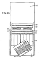
- Figure 5A shows a plan view of the apparatus of Figure I with the clamp roller assemblies 22 removed.
- the passbook 86 is placed upon the feed tray 14 and a portion of the passbook 86 urged to engage the conveyor belt 16.
- the operator of the passbook printer then provides indication that a printing operation is to be executed.
- the indication may be automatically by detection of the passbook 86 on the feed tray 14 or may be provided by switch or through communication through the teller's keypad. It does not matter from the point of view of the present invention how that indication is provided.
- the passbook printer raises the barrier 40 through slots in the printing bed 18 of the flat bed 12.
- the barrier 40 lies across the path of the conveyor belt 16.
- Figure 5B shows the next stage of operation.
- the conveyor belt 16 is activated to drive the passbook 86 by frictional coupling in the direction of the third arrow 88 until a corner of the passbook 86 engages the raised barrier 40.
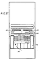
- Figure 5C shows the next stage in alignment of the passbook 86 against the barrier 40.
- the conveyor belt 16 continues to move after the corner of the passbook 86 has first engaged the barrier 40. Frictional coupling between the conveyor belt 16 and the passbook 86 causes the remaining portion of the passbook 86 which has not engaged the barrier 40 to swing round as indicated by the fourth curved arrow 90 to align one of the edges of the passbook 86 with the barrier 40.
- the conveyor belt 16 is maintained moving for a predetermined time at least equal to the amount of time required for the sequence of actions shown in Figures 5A to 5C. In practice, an excess allowance of time is provided so that the consequences of inattentiveness or poor frictional coupling may be avoided.
- Figure 5D corresponds to Figure 5C except in that the passbook 86 has become aligned with the barrier 40 with a different edge of the passbook 86 in alignment with the barrier 40.
- This different situation is in consequence of the passbook 86 having been at a different angle on the feed tray 14 from that depicted in Figure 5A.
- the passbook 86 if merely slid onto the feed tray 14 may end up with any one of its four edges aligned against the barrier 40. Whilst it is possible to detect alignments other than that shown in Figure 5C and not print the passbook 86, the present invention seeks to provide that the passbook 86 may be printed whatever the alignment thereof against the barrier 40.
- the sensor 80 on the printhead assembly 38 is employed not only to detect the orientation of the passbook 86, but also to detect the position of the passbook 86 transversely to the direction of movement of the conveyor belt 16.
- the passbook 86 is, therefore, able to continue in its progress across the printing bed 18.
- the clamp roller assembly 22 closest to the conveyor belt 16 is lowered by rotation of its associated clamp rod 24 through action of the solenoid 26.
- the first drive motor 42 is activated to advance the passbook 86 a predetermined number of steps under the printhead assembly 38 for the printhead assembly 38 to commence a scanning operation.
- the printhead assembly 38 is first taken to its home position to one side of the passbook printer.
- the sensor 80 and the matrix printhead 82 are then moved together across the passbook 86.
- the sensor 80 first detects reflected light it knows which step of the stepping motor 76 whereat the passbook 86 commences.
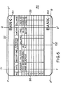
- Figure 6 shows details of the passbook 86. If the passbook 86 ends up with a first edge 92 thereof aligned against the barrier 40, the sensor 80 executes the line P-P'.
- the electronic assembly 56 starts a step count S of the stepping motor 76 whenever the photosensor 80 detects the edge of the passbook 86.
- the photosensor 80 detects no printing except that of a first dense mark 94.
- the first dense mark 94 takes the form of bold letter printing.
- the width of the printed lines are such that the photosensor in maintaining its count of the steps S detects darkness for four or more steps. Depending upon the thickness of the printing, this number can be changed according to the desire of the particular design.
- the sensor 80 will execute the line T-T' across the passbook 86.
- the ordinary printing on the passbook and previous printing by the matrix printhead 82 are of such a thickness that the sensor 80 does not see darkness for the requisite number of four steps. Accordingly, all ordinary printing upon the passbook 86 is ignored by the sensor 80.
- the sensor 80 sees no dense mark 94 whatever. In seeing no dense mark 94 in the totality of its possible excursion of steps S MAX the passbook printer may be certain that the passbook 86 has been aligned with its second edge 96 against the barrier 40.
- the sensor 80 executes the line Q-Q' across the passbook 86.
- the passbook 86 is provided with a second dense mark 100 similar to the first dense mark 94 and immediately therebelow.
- the sensor 80 therefore, encounters two dense marks along the line Q-Q'. In detecting the two dense marks, the passbook printer may be sure that the third edge 98 of the passbook 86 was the one that came into alignment with the barrier 40.
- the sensor 80 executes the line R-R' across the passbook 86. In so doing, it detects the second dense mark 100 very early in its execution of the line R-R'. In fact, it detects the second dense mark in less than a second predetermined number of steps W of the stepping motor 76 from the point where the sensor 80 first detected the edge of the passbook 86.
- the passbook printer detects a dense mark less than the second predetermined number of steps W from the point whereat the sensor 80 first detected the edge of the passbook 86, it can be sure that the passbook 86 has become aligned with the fourth edge 102 thereof having been up against the barrier 40.
- the passbook printer is able to detect which way round the passbook 86 has been aligned.
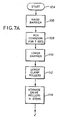
- Figure 7A shows a first portion of a flowchart indicating the activities of the electronic assembly 56 in controlling the passbook printer.
- the electronic assembly 56 goes to a first operation 106 where it raises the barrier 40.
- the electronic assembly 56 performs a second operation 108 wherein the conveyor 16 is run for a predetermined number of seconds long enough to align the passbook 86 against the barrier 40.
- the electronic assembly 56 commands the second solenoid 52 to be de-energised for the first spring 54 to lower the barrier 40 in a third operation 110.
- the electronic assembly 56 energises the solenoid 26 in a fourth operation 112 for the clamp rollers 22 to grip the passbook 86 against the drive rollers 50.
- the electronic assembly 56 performs a fifth operation 114 to advance the drive rollers 50 through a predetermined number M of steps of the first drive motor 42 to bring the passbook 86 into one of the positions relative to the sensor 80 indicated in Figure 6.
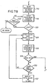
- Figure 7B shows further portions of the operation of the electronic assembly 56. Having advanced the passbook 86 the electronic assembly 56 performs a sixth operation 116 to send the printhead assembly 82, 80 to its home position at the extreme lefthand side of Figure 4 as it is shown. This may be accomplished by stepping the stepping motor 76 until a microswitch (not shown) makes electrical contact or simply by stepping the stepping motor 76 for a predetermined period of time to make sure that enough steps have been administered to drive the assembly 80, 82 hard against its end stop.
- a microswitch not shown
- the passbook printer through its electronic assembly 56 goes on to step the printhead assembly 80,82 across the passbook 86 in a seventh operation 118.
- a first test 120 of the output of the sensor 80 is made to see if the sensor 80 has detected any light. If no light has been detected, a second test is performed to see if the printhead assembly 80,82 has gone through its extreme righthand position. If not, operation passes back to the seventh operation for another step to be administered to the printhead assembly 80,82. If the maximum excursion has been reached with no light having been detected, then no passbook 86 at all has been presented to the passbook printer and indication is provided before the printer shuts down.
- the electronic assembly 56 starts counting the steps of the stepping motor 76 having first set the step count S equal to zero and also having set the count of the number of dense marks encountered M also equal to zero.
- the printhead assembly 80,82 continues to be stepped across the passbook 86 in a ninth operation 126 and its steps are counted.
- a third test 128 is applied to see if the maximum number of steps S MAX has been reached. If the maximum number of steps S MAX has been reached, then the routine exits to the testing phase shown in Figure 7C. If not, a fourth test 130 is applied to test if the sensor 80 has seen darkness for four or more steps.
- the dense mark is not encountered and control is returned to the eighth operation 124. If it has encountered the dense mark 94,100 then the dense mark count M is incremented by one and the value of the step count (S M ) whereat the dense mark was first encountered is noted down. All this is achieved in a tenth operation 132. Thereafter, the tenth operation 132 returns back to the eighth operation 124.
- Figure 7C shows the testing phase of the operational sequence shown in Figures 7A and 7B. If the third test 128 showed that the steps count S had equalled or exceeded the maximum step count S MAX , then control is transferred to a fifth test 134 which tests if the dense mark count M is equal to 0. If the dense mark count M is equal to 0, then the passbook 86 is aligned with the second edge 96 having been presented to the barrier 40. Control is, therefore, transferred to a second edge routine 136.
- the sixth test 138 tests if the dense mark count M is equal to 2. If the dense mark count M is equal to 2, then the passbook 86 has been presented for the third edge 98 to have come into alignment with the barrier 40. The control is, therefore, passed to a third edge routine 140.
- the seventh test 142 tests whether the number of steps of the step count S noted down on encountering the dense mark, namely S M exceeds the first predetermined number of steps A. If it does, then control is passed to a first edge routine 144. If not, then control passes to an eighth test 146.
- the eighth test 146 tests whether the noted down number of steps S M was less than or equal to a second predetermined number of steps W. If it is, then control is passed to a fourth edge routine 148. If not, then there is something wrong, namely a wrong kind of book or document having been presented to the passbook printer. Thus, control passes to an error routine 150 which indicates the error and prevents any further action.
- Figure 7D shows the first edge routine 144 of Figure 7C.
- the electronic assembly 56 advances the drive rollers 50 by means of the first drive motor 42 to the selected line already indicated to the passbook printer by the teller using it. Thereafter, the electronic assembly 56 executes a twelfth operation 154 wherein the matrix printhead 82 is swept just once across the passbook 86 to print a normal row of upright characters. Thereafter, in a thirteenth operation 156 the drive rollers 50 are reversed as is the conveyor belt 16 to return the passbook 86 to the user. Thereafter, operation of the passbook printer ceases.
- Figure 7E shows the fourth edge routine 148 of Figure 7C.
- the electronic assemblies 56 perform a fourteenth operation 158 to advance the drive rollers 50 to move the book for the selected line to be beneath the printhead 82. However, it does not move the book the same distance as does the eleventh operation 152 since the book is upside down and must move a different number of steps of the first drive motor 42.
- the fourteenth operation 158 the electronic assembly 56 moves the passbook 86 the required number of steps to bring the upside down desired line beneath the printhead 82.
- the electronic assembly 56 performs a fifteenth operation 160 to print a single row of printing across the passbook 86, but with the matrix characters upside down with the characters from the control memory inverted such that the first row becomes the seventh row, the second row becomes the sixth row, and so on. Further, the directions left and right are changed so that the characters come out in the opposite sequence of printing. Having performed the fifteenth operation 160, the electronic assembly 56 reverses the drive rollers 50 and the conveyor belt 16 as for the thirteenth operation 156 in a sixteenth operation 162 to return the passbook 86 to the teller.
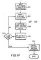
- Figure 7F shows the situation where either the second edge 96 or the third edge 98 have been aligned with the barrier 40.
- Figure 7F is equally applicable as being descriptive of the second edge routine 136 or the third edge routine 140 of Figure 7C.
- a seventeenth operation 164 the electronic assembly 56 moves the printhead 82 to be in alignment with the desired line on the passbook 86 whereat the printing is required. It is to be remembered that in both these instances the passbook is sideways on the printhead 82. The electronic assembly 56, therefore, rescrambles the characters to be sent to the matrix printhead 82 such that the rows become columns and the columns become rows.
- the printhead assembly 38 being swept through nine vertical print positions to create the character.
- the printhead 82 first starts either at the top or bottom of the line to be printed and prints one character. Control is then passed to a nineteenth operation 168 wherein the electronic assembly 56 advances the drive rollers 50 to move the passbook 86 by one character width. Thereafter, in a twentieth operation 170 the next character in whichever order is required is presented for printing. If the line is not full, control is returned by a ninth test 172 to the eighteenth operation 166. If the line of printing is finished, then in a twenty-first operation 174 the drive rollers 50 and the conveyor belt 16 are reversed, once again to return the passbook 86 to the teller.
- the present invention is not restricted to banking passbooks, but may be used on any transactional document which may be printed upon presentation in a flat form to a printer.
Landscapes
- Physics & Mathematics (AREA)
- General Physics & Mathematics (AREA)
- Engineering & Computer Science (AREA)
- Theoretical Computer Science (AREA)
- Handling Of Cut Paper (AREA)
- Financial Or Insurance-Related Operations Such As Payment And Settlement (AREA)
- Accessory Devices And Overall Control Thereof (AREA)
Claims (6)
Applications Claiming Priority (2)
| Application Number | Priority Date | Filing Date | Title |
|---|---|---|---|
| GB8412707 | 1984-05-18 | ||
| GB08412707A GB2159100B (en) | 1984-05-18 | 1984-05-18 | Passbook printer |
Related Parent Applications (2)
| Application Number | Title | Priority Date | Filing Date |
|---|---|---|---|
| EP85302043A Division-Into EP0165660B1 (fr) | 1984-05-18 | 1985-03-25 | Imprimante pour livrets d'épargne |
| EP85302043A Division EP0165660B1 (fr) | 1984-05-18 | 1985-03-25 | Imprimante pour livrets d'épargne |
Publications (3)
| Publication Number | Publication Date |
|---|---|
| EP0244879A2 EP0244879A2 (fr) | 1987-11-11 |
| EP0244879A3 EP0244879A3 (en) | 1987-11-19 |
| EP0244879B1 true EP0244879B1 (fr) | 1990-12-12 |
Family
ID=10561153
Family Applications (2)
| Application Number | Title | Priority Date | Filing Date |
|---|---|---|---|
| EP87107770A Expired - Lifetime EP0244879B1 (fr) | 1984-05-18 | 1985-03-25 | Imprimante pour livrets d'épargne |
| EP85302043A Expired EP0165660B1 (fr) | 1984-05-18 | 1985-03-25 | Imprimante pour livrets d'épargne |
Family Applications After (1)
| Application Number | Title | Priority Date | Filing Date |
|---|---|---|---|
| EP85302043A Expired EP0165660B1 (fr) | 1984-05-18 | 1985-03-25 | Imprimante pour livrets d'épargne |
Country Status (8)
| Country | Link |
|---|---|
| US (1) | US4743129A (fr) |
| EP (2) | EP0244879B1 (fr) |
| JP (1) | JPH0630920B2 (fr) |
| BR (1) | BR8502054A (fr) |
| DE (2) | DE3580920D1 (fr) |
| FR (1) | FR2564381B1 (fr) |
| GB (1) | GB2159100B (fr) |
| WO (1) | WO1985005325A1 (fr) |
Cited By (1)
| Publication number | Priority date | Publication date | Assignee | Title |
|---|---|---|---|---|
| CN1083774C (zh) * | 1996-04-25 | 2002-05-01 | 株式会社Imes | 打印机 |
Families Citing this family (78)
| Publication number | Priority date | Publication date | Assignee | Title |
|---|---|---|---|---|
| US4920882A (en) * | 1987-09-03 | 1990-05-01 | W. H. Brady Co. | Electronic labeler with printhead and web sensor combined for concurrent travel, and assemblies of identification devices therefor |
| GB2209997B (en) * | 1987-09-22 | 1991-07-17 | Unisys Corp | Printing apparatus |
| US4833591A (en) * | 1987-12-30 | 1989-05-23 | Pitney Bowes Inc. | Method for aligning a moving substrate and a read or write head |
| US4855607A (en) * | 1987-12-30 | 1989-08-08 | Pitney Bowes, Inc. | Apparatus for aligning a moving substrate and a read or write head |
| JP3004990B2 (ja) * | 1988-03-08 | 2000-01-31 | キヤノン株式会社 | プリンタ |
| GB8819194D0 (en) * | 1988-08-12 | 1988-09-14 | Mirpuri S P | Improved pos equipment |
| US4841859A (en) * | 1988-11-21 | 1989-06-27 | Komori Printing Machinery Co., Ltd. | Side lay control apparatus for sheet-fed printing press |
| DE3842583A1 (de) * | 1988-12-17 | 1990-06-21 | Reiner Ernst Gmbh Co Kg | Vorrichtung zum zufuehren von belegen in eine druck- und/oder lesestation |
| KR930000181B1 (ko) * | 1989-02-02 | 1993-01-11 | 도쿄덴기 가부시기가이샤 | 인자기 |
| JPH02305739A (ja) * | 1989-04-28 | 1990-12-19 | Ncr Corp | 通帳印字装置における印字媒体搬送機構 |
| US4944616A (en) * | 1989-11-06 | 1990-07-31 | Ncr Corporation | Passbook read/write mechanism |
| JP2697276B2 (ja) * | 1989-11-14 | 1998-01-14 | セイコーエプソン株式会社 | プリンタ |
| US5192140A (en) * | 1989-11-24 | 1993-03-09 | Kabushiki Kaisha Toshiba | Apparatus and method of printing data in a book, a notebook, or the like |
| US5267799A (en) * | 1989-11-24 | 1993-12-07 | Kabushiki Kaisha Toshiba | Apparatus and method of printing data in a book, a notebook, or the like |
| JPH03169664A (ja) * | 1989-11-30 | 1991-07-23 | Ncr Corp | 通帳印字機 |
| US5183347A (en) * | 1989-12-15 | 1993-02-02 | Kabushiki Kaisha Toshiba | Apparatus for printing images on booklets |
| US5035521A (en) * | 1990-02-06 | 1991-07-30 | Addressease, Inc. | Envelope printing mechanism |
| FI88477C (fi) * | 1991-03-25 | 1993-05-25 | Icl Personal Systems Oy | Skrivare |
| JPH05131701A (ja) * | 1991-11-14 | 1993-05-28 | Hitachi Ltd | 通帳プリンタ |
| JPH05229198A (ja) * | 1992-02-25 | 1993-09-07 | Sony Corp | カード印刷装置 |
| US5277507A (en) * | 1992-04-08 | 1994-01-11 | Stuart F. Cooper, Co. | Sheet feeder for engraving press |
| US5423619A (en) * | 1992-09-30 | 1995-06-13 | Sony Corporation | Card printing apparatus |
| WO1994022117A1 (fr) * | 1993-03-23 | 1994-09-29 | Siemens Nixdorf Informationssysteme Aktiengesellschaft | Imprimante pour documents et procede permettant la saisie de documents a l'aide de numeros de controle et au moyen de cette imprimante |
| JP3156455B2 (ja) * | 1993-08-10 | 2001-04-16 | 富士通株式会社 | 冊子状媒体の磁気データ処理機構及び冊子状媒体処理装置 |
| US5507481A (en) * | 1994-06-10 | 1996-04-16 | Interbold | Automated teller machine passbook transport mechanism |
| US5408927A (en) * | 1994-09-12 | 1995-04-25 | Pitney Bowes Inc. | Tax stamp machine |
| DE19535040B4 (de) * | 1995-09-21 | 2004-08-26 | Walter Petter | Vorrichtung zum Bedrucken von Schriftstücken |
| JP3208318B2 (ja) * | 1996-03-06 | 2001-09-10 | インターナショナル・ビジネス・マシーンズ・コーポレーション | カードホルダ |
| TW362071B (en) * | 1996-05-15 | 1999-06-21 | Seiko Epson Corp | Printer |
| US5746521A (en) * | 1996-12-20 | 1998-05-05 | Intermec Corporation | Thermal printhead with integrated printhead position sensor |
| JP3711677B2 (ja) * | 1997-01-14 | 2005-11-02 | セイコーエプソン株式会社 | プリンタ |
| DE59800407D1 (de) * | 1998-05-05 | 2001-02-01 | Maurer Electronics Gmbh | Verfahren und Kassette zum Beschriften eines heftartigen Gegenstandes in einer Beschriftungsstation |
| US6530047B1 (en) | 1999-10-01 | 2003-03-04 | Stmicroelectronics Limited | System and method for communicating with an integrated circuit |
| US6601189B1 (en) | 1999-10-01 | 2003-07-29 | Stmicroelectronics Limited | System and method for communicating with an integrated circuit |
| US6779145B1 (en) | 1999-10-01 | 2004-08-17 | Stmicroelectronics Limited | System and method for communicating with an integrated circuit |
| US6487683B1 (en) | 1999-10-01 | 2002-11-26 | Stmicroelectronics Limited | Microcomputer debug architecture and method |
| US6557119B1 (en) | 1999-10-01 | 2003-04-29 | Stmicroelectronics Limited | Microcomputer debug architecture and method |
| US6918065B1 (en) | 1999-10-01 | 2005-07-12 | Hitachi, Ltd. | Method for compressing and decompressing trace information |
| US6615370B1 (en) | 1999-10-01 | 2003-09-02 | Hitachi, Ltd. | Circuit for storing trace information |
| US7793261B1 (en) | 1999-10-01 | 2010-09-07 | Stmicroelectronics Limited | Interface for transferring debug information |
| US6567932B2 (en) | 1999-10-01 | 2003-05-20 | Stmicroelectronics Limited | System and method for communicating with an integrated circuit |
| US6463553B1 (en) | 1999-10-01 | 2002-10-08 | Stmicroelectronics, Ltd. | Microcomputer debug architecture and method |
| US6665816B1 (en) | 1999-10-01 | 2003-12-16 | Stmicroelectronics Limited | Data shift register |
| US6684348B1 (en) | 1999-10-01 | 2004-01-27 | Hitachi, Ltd. | Circuit for processing trace information |
| US6591369B1 (en) | 1999-10-01 | 2003-07-08 | Stmicroelectronics, Ltd. | System and method for communicating with an integrated circuit |
| US6542983B1 (en) | 1999-10-01 | 2003-04-01 | Hitachi, Ltd. | Microcomputer/floating point processor interface and method |
| DE10218252B4 (de) * | 2001-05-02 | 2014-04-30 | Ruhlamat Gmbh | Verfahren und Vorrichtung zum Anbringen von Sicherungsmassnahmen an Passbüchern |
| JP4556419B2 (ja) * | 2003-11-04 | 2010-10-06 | セイコーエプソン株式会社 | 記録装置およびローラ押圧装置 |
| US6856785B1 (en) * | 2003-12-22 | 2005-02-15 | Xerox Corporation | Retractable registration system and method of use |
| US7775966B2 (en) | 2005-02-24 | 2010-08-17 | Ethicon Endo-Surgery, Inc. | Non-invasive pressure measurement in a fluid adjustable restrictive device |
| US7658196B2 (en) | 2005-02-24 | 2010-02-09 | Ethicon Endo-Surgery, Inc. | System and method for determining implanted device orientation |
| US7927270B2 (en) | 2005-02-24 | 2011-04-19 | Ethicon Endo-Surgery, Inc. | External mechanical pressure sensor for gastric band pressure measurements |
| US7775215B2 (en) | 2005-02-24 | 2010-08-17 | Ethicon Endo-Surgery, Inc. | System and method for determining implanted device positioning and obtaining pressure data |
| US8016744B2 (en) | 2005-02-24 | 2011-09-13 | Ethicon Endo-Surgery, Inc. | External pressure-based gastric band adjustment system and method |
| US7699770B2 (en) | 2005-02-24 | 2010-04-20 | Ethicon Endo-Surgery, Inc. | Device for non-invasive measurement of fluid pressure in an adjustable restriction device |
| US8066629B2 (en) | 2005-02-24 | 2011-11-29 | Ethicon Endo-Surgery, Inc. | Apparatus for adjustment and sensing of gastric band pressure |
| US20060261540A1 (en) * | 2005-05-17 | 2006-11-23 | Xerox Corporation | Sheet deskewing with automatically variable differential NIP force sheet driving rollers |
| US20070132179A1 (en) * | 2005-12-14 | 2007-06-14 | Pitney Bowes Incorporated | Method and device for aligning sheets in a transport module |
| US8870742B2 (en) | 2006-04-06 | 2014-10-28 | Ethicon Endo-Surgery, Inc. | GUI for an implantable restriction device and a data logger |
| US8152710B2 (en) | 2006-04-06 | 2012-04-10 | Ethicon Endo-Surgery, Inc. | Physiological parameter analysis for an implantable restriction device and a data logger |
| US7631868B2 (en) * | 2006-05-05 | 2009-12-15 | Xerox Corporation | Scuffer apparatus and method |
| US8187163B2 (en) | 2007-12-10 | 2012-05-29 | Ethicon Endo-Surgery, Inc. | Methods for implanting a gastric restriction device |
| US8100870B2 (en) | 2007-12-14 | 2012-01-24 | Ethicon Endo-Surgery, Inc. | Adjustable height gastric restriction devices and methods |
| US8142452B2 (en) | 2007-12-27 | 2012-03-27 | Ethicon Endo-Surgery, Inc. | Controlling pressure in adjustable restriction devices |
| US8377079B2 (en) | 2007-12-27 | 2013-02-19 | Ethicon Endo-Surgery, Inc. | Constant force mechanisms for regulating restriction devices |
| US8192350B2 (en) | 2008-01-28 | 2012-06-05 | Ethicon Endo-Surgery, Inc. | Methods and devices for measuring impedance in a gastric restriction system |
| US8591395B2 (en) | 2008-01-28 | 2013-11-26 | Ethicon Endo-Surgery, Inc. | Gastric restriction device data handling devices and methods |
| US8337389B2 (en) | 2008-01-28 | 2012-12-25 | Ethicon Endo-Surgery, Inc. | Methods and devices for diagnosing performance of a gastric restriction system |
| US8221439B2 (en) | 2008-02-07 | 2012-07-17 | Ethicon Endo-Surgery, Inc. | Powering implantable restriction systems using kinetic motion |
| US7844342B2 (en) | 2008-02-07 | 2010-11-30 | Ethicon Endo-Surgery, Inc. | Powering implantable restriction systems using light |
| US8114345B2 (en) | 2008-02-08 | 2012-02-14 | Ethicon Endo-Surgery, Inc. | System and method of sterilizing an implantable medical device |
| US8057492B2 (en) | 2008-02-12 | 2011-11-15 | Ethicon Endo-Surgery, Inc. | Automatically adjusting band system with MEMS pump |
| US8591532B2 (en) | 2008-02-12 | 2013-11-26 | Ethicon Endo-Sugery, Inc. | Automatically adjusting band system |
| US8034065B2 (en) | 2008-02-26 | 2011-10-11 | Ethicon Endo-Surgery, Inc. | Controlling pressure in adjustable restriction devices |
| US8187162B2 (en) | 2008-03-06 | 2012-05-29 | Ethicon Endo-Surgery, Inc. | Reorientation port |
| US8233995B2 (en) | 2008-03-06 | 2012-07-31 | Ethicon Endo-Surgery, Inc. | System and method of aligning an implantable antenna |
| US9463647B1 (en) * | 2015-07-15 | 2016-10-11 | Toshiba Tec Kabushiki Kaisha | Printer and method for operating the same |
| JP6475376B2 (ja) * | 2018-02-14 | 2019-02-27 | Necプラットフォームズ株式会社 | 通帳処理装置 |
Family Cites Families (24)
| Publication number | Priority date | Publication date | Assignee | Title |
|---|---|---|---|---|
| GB1175146A (en) * | 1967-03-29 | 1969-12-23 | Harris Intertype Corp | Sheet Material Shaping Apparatus |
| US3849631A (en) * | 1971-03-04 | 1974-11-19 | Burroughs Corp | Punched card, badge and credit card reader |
| US4015523A (en) * | 1972-09-01 | 1977-04-05 | Aes Technology Systems, Inc. | Method and apparatus for feeding and printing documents |
| US3814227A (en) * | 1972-09-27 | 1974-06-04 | Honeywell Inc | Matrix print rotation |
| US3951251A (en) * | 1974-07-31 | 1976-04-20 | Bunker Ramo Corporation | Document positioning means for printing apparatus |
| IT1020820B (it) * | 1974-09-18 | 1977-12-30 | Olivetti & Co Spa | Dispositivo di alimentazione auto matica di documenti per macchine contabili o simili |
| JPS5722264Y2 (fr) * | 1975-03-10 | 1982-05-14 | ||
| JPS5854993B2 (ja) * | 1975-09-30 | 1983-12-07 | 富士通株式会社 | 印字制御方法 |
| JPS5245218A (en) * | 1976-06-11 | 1977-04-09 | Omron Tateisi Electronics Co | Print control system |
| JPS5492408A (en) * | 1977-12-28 | 1979-07-21 | Ricoh Kk | Paper supplying apparatus of letter printing apparatus |
| JPS54127713A (en) * | 1978-03-28 | 1979-10-03 | Mitsubishi Electric Corp | Printer |
| US4265556A (en) * | 1978-12-21 | 1981-05-05 | International Business Machines Corporation | Apparatus for setting proportional margins based upon the width of a scanned sheet of paper |
| FR2464523B1 (fr) * | 1979-08-30 | 1985-11-22 | Cii Honeywell Bull | Appareil de traitement de supports d'informations |
| JPS56144983A (en) * | 1980-04-15 | 1981-11-11 | Brother Ind Ltd | Typewriter |
| DE3014513A1 (de) * | 1980-04-16 | 1981-10-22 | Scantron GmbH & Co Elektronische Lesegeräte KG, 6000 Frankfurt | Verfahren und vorrichtung zum indentifizieren von gegenstaenden |
| JPS56162177A (en) * | 1980-05-16 | 1981-12-12 | Matsushita Graphic Commun Syst Inc | Mark sheet and system |
| JPS57137180A (en) * | 1981-02-18 | 1982-08-24 | Canon Inc | Printer |
| JPS5831788A (ja) * | 1981-08-18 | 1983-02-24 | Ricoh Co Ltd | プリンタにおける印字位置制御装置 |
| JPS5855270A (ja) * | 1981-09-30 | 1983-04-01 | Hitachi Ltd | インサ−タプリンタの書式制御方式 |
| JPS5892031A (ja) * | 1981-11-27 | 1983-06-01 | Fujitsu Ltd | 読取方式 |
| US4442769A (en) * | 1981-12-24 | 1984-04-17 | Ncr Corporation | Staging apparatus used in a sheet feeding environment |
| DE3215225C2 (de) * | 1982-04-23 | 1984-05-30 | Kienzle Apparate Gmbh, 7730 Villingen-Schwenningen | Kombinierte Druck- und Leseeinrichtung |
| JPS5929185A (ja) * | 1982-08-10 | 1984-02-16 | Fujitsu Ltd | プリンタ装置 |
| US4470591A (en) * | 1982-08-12 | 1984-09-11 | Xerox Corporation | Variable force document handling system |
-
1984
- 1984-05-18 GB GB08412707A patent/GB2159100B/en not_active Expired
- 1984-07-30 FR FR848412090A patent/FR2564381B1/fr not_active Expired - Lifetime
-
1985
- 1985-03-25 DE DE8787107770T patent/DE3580920D1/de not_active Expired - Lifetime
- 1985-03-25 EP EP87107770A patent/EP0244879B1/fr not_active Expired - Lifetime
- 1985-03-25 EP EP85302043A patent/EP0165660B1/fr not_active Expired
- 1985-03-25 DE DE8585302043T patent/DE3564220D1/de not_active Expired
- 1985-04-30 BR BR8502054A patent/BR8502054A/pt not_active IP Right Cessation
- 1985-05-15 JP JP60103626A patent/JPH0630920B2/ja not_active Expired - Lifetime
- 1985-05-17 US US06/796,028 patent/US4743129A/en not_active Expired - Lifetime
- 1985-05-17 WO PCT/GB1985/000209 patent/WO1985005325A1/fr not_active Ceased
Cited By (1)
| Publication number | Priority date | Publication date | Assignee | Title |
|---|---|---|---|---|
| CN1083774C (zh) * | 1996-04-25 | 2002-05-01 | 株式会社Imes | 打印机 |
Also Published As
| Publication number | Publication date |
|---|---|
| GB2159100A (en) | 1985-11-27 |
| EP0165660B1 (fr) | 1988-08-10 |
| DE3564220D1 (en) | 1988-09-15 |
| FR2564381B1 (fr) | 1990-02-23 |
| JPH0630920B2 (ja) | 1994-04-27 |
| US4743129A (en) | 1988-05-10 |
| EP0244879A2 (fr) | 1987-11-11 |
| GB2159100B (en) | 1988-10-26 |
| EP0165660A1 (fr) | 1985-12-27 |
| FR2564381A1 (fr) | 1985-11-22 |
| GB8412707D0 (en) | 1984-06-27 |
| BR8502054A (pt) | 1985-12-31 |
| DE3580920D1 (de) | 1991-01-24 |
| WO1985005325A1 (fr) | 1985-12-05 |
| EP0244879A3 (en) | 1987-11-19 |
| JPS6189071A (ja) | 1986-05-07 |
Similar Documents
| Publication | Publication Date | Title |
|---|---|---|
| EP0244879B1 (fr) | Imprimante pour livrets d'épargne | |
| US4981059A (en) | Cutting mechanism control for dot matrix printer | |
| US4339208A (en) | Optical sensing of wire matrix printers | |
| EP0571804A2 (fr) | Imprimante par jet d'encre multi-têtes | |
| WO1998009822A1 (fr) | Imprimante d'etiquettes a decoupeuse | |
| AU613959B2 (en) | Document handling apparatus | |
| JPH0248430B2 (fr) | ||
| GB2197824A (en) | Document printer | |
| GB2235163A (en) | Marking supports for laboratory samples | |
| US4407597A (en) | Paper feeding apparatus for printing apparatus | |
| JPS5845066B2 (ja) | バ−コ−ド情報記録方法 | |
| US20080069620A1 (en) | Hand-operated Printer and Printer Dock Configured to Facilitate Auxiliary Printing | |
| JPS6324479A (ja) | ビツトコ−ド化デ−タを有するカ−ド用読取装置 | |
| EP0015553A1 (fr) | Méthode et dispositif pour déterminer la position du support d'impression dans une imprimante rapide | |
| EP0294447A1 (fr) | Systeme de determination des espacements entre les orifices de cartouches d'impression cooperatives d'une imprimante a jet d'encre. | |
| US3857020A (en) | Automatic line tracker | |
| EP0146587A1 (fr) | Module d'application de caractere de filet magnetique. | |
| US3729618A (en) | Scanning mechanism and printer | |
| TW568836B (en) | Image forming apparatus having position sensing device | |
| JPS6233629B2 (fr) | ||
| EP0361923A1 (fr) | Dispositif et procédé pour contrôler le positionnement d'éléments de marquage pour une imprimante d'impact en série | |
| US6535145B1 (en) | Ideographic keyboard and method | |
| US5399038A (en) | Dual line slip printer | |
| JP3638197B2 (ja) | プリンタ装置 | |
| SE429116B (sv) | Anordning for pappersstyrning i skrivutrustningar |
Legal Events
| Date | Code | Title | Description |
|---|---|---|---|
| PUAI | Public reference made under article 153(3) epc to a published international application that has entered the european phase |
Free format text: ORIGINAL CODE: 0009012 |
|
| PUAL | Search report despatched |
Free format text: ORIGINAL CODE: 0009013 |
|
| 17P | Request for examination filed |
Effective date: 19870527 |
|
| AC | Divisional application: reference to earlier application |
Ref document number: 165660 Country of ref document: EP |
|
| AK | Designated contracting states |
Kind code of ref document: A2 Designated state(s): BE DE IT NL SE |
|
| AK | Designated contracting states |
Kind code of ref document: A3 Designated state(s): BE DE IT NL SE |
|
| 17Q | First examination report despatched |
Effective date: 19891128 |
|
| GRAA | (expected) grant |
Free format text: ORIGINAL CODE: 0009210 |
|
| AC | Divisional application: reference to earlier application |
Ref document number: 165660 Country of ref document: EP |
|
| AK | Designated contracting states |
Kind code of ref document: B1 Designated state(s): BE DE IT NL SE |
|
| REF | Corresponds to: |
Ref document number: 3580920 Country of ref document: DE Date of ref document: 19910124 |
|
| ITF | It: translation for a ep patent filed | ||
| PLBE | No opposition filed within time limit |
Free format text: ORIGINAL CODE: 0009261 |
|
| STAA | Information on the status of an ep patent application or granted ep patent |
Free format text: STATUS: NO OPPOSITION FILED WITHIN TIME LIMIT |
|
| 26N | No opposition filed | ||
| PGFP | Annual fee paid to national office [announced via postgrant information from national office to epo] |
Ref country code: BE Payment date: 19920409 Year of fee payment: 8 |
|
| ITTA | It: last paid annual fee | ||
| PG25 | Lapsed in a contracting state [announced via postgrant information from national office to epo] |
Ref country code: BE Effective date: 19930331 |
|
| BERE | Be: lapsed |
Owner name: UNISYS CORP. Effective date: 19930331 |
|
| PGFP | Annual fee paid to national office [announced via postgrant information from national office to epo] |
Ref country code: SE Payment date: 19940217 Year of fee payment: 10 |
|
| PGFP | Annual fee paid to national office [announced via postgrant information from national office to epo] |
Ref country code: DE Payment date: 19940329 Year of fee payment: 10 |
|
| PGFP | Annual fee paid to national office [announced via postgrant information from national office to epo] |
Ref country code: NL Payment date: 19940331 Year of fee payment: 10 |
|
| EAL | Se: european patent in force in sweden |
Ref document number: 87107770.7 |
|
| PG25 | Lapsed in a contracting state [announced via postgrant information from national office to epo] |
Ref country code: SE Effective date: 19950326 |
|
| PG25 | Lapsed in a contracting state [announced via postgrant information from national office to epo] |
Ref country code: NL Effective date: 19951001 |
|
| NLV4 | Nl: lapsed or anulled due to non-payment of the annual fee |
Effective date: 19951001 |
|
| PG25 | Lapsed in a contracting state [announced via postgrant information from national office to epo] |
Ref country code: DE Effective date: 19951201 |
|
| EUG | Se: european patent has lapsed |
Ref document number: 87107770.7 |