EP0244578A2 - Elektromotorisch angetriebene Schwenkvorrichtung - Google Patents
Elektromotorisch angetriebene Schwenkvorrichtung Download PDFInfo
- Publication number
- EP0244578A2 EP0244578A2 EP87102537A EP87102537A EP0244578A2 EP 0244578 A2 EP0244578 A2 EP 0244578A2 EP 87102537 A EP87102537 A EP 87102537A EP 87102537 A EP87102537 A EP 87102537A EP 0244578 A2 EP0244578 A2 EP 0244578A2
- Authority
- EP
- European Patent Office
- Prior art keywords
- rocker
- swivel device
- butterfly valve
- threaded nut
- threaded
- Prior art date
- Legal status (The legal status is an assumption and is not a legal conclusion. Google has not performed a legal analysis and makes no representation as to the accuracy of the status listed.)
- Granted
Links
Images
Classifications
-
- F—MECHANICAL ENGINEERING; LIGHTING; HEATING; WEAPONS; BLASTING
- F16—ENGINEERING ELEMENTS AND UNITS; GENERAL MEASURES FOR PRODUCING AND MAINTAINING EFFECTIVE FUNCTIONING OF MACHINES OR INSTALLATIONS; THERMAL INSULATION IN GENERAL
- F16H—GEARING
- F16H25/00—Gearings comprising primarily only cams, cam-followers and screw-and-nut mechanisms
- F16H25/18—Gearings comprising primarily only cams, cam-followers and screw-and-nut mechanisms for conveying or interconverting oscillating or reciprocating motions
- F16H25/20—Screw mechanisms
-
- F—MECHANICAL ENGINEERING; LIGHTING; HEATING; WEAPONS; BLASTING
- F16—ENGINEERING ELEMENTS AND UNITS; GENERAL MEASURES FOR PRODUCING AND MAINTAINING EFFECTIVE FUNCTIONING OF MACHINES OR INSTALLATIONS; THERMAL INSULATION IN GENERAL
- F16K—VALVES; TAPS; COCKS; ACTUATING-FLOATS; DEVICES FOR VENTING OR AERATING
- F16K31/00—Actuating devices; Operating means; Releasing devices
- F16K31/02—Actuating devices; Operating means; Releasing devices electric; magnetic
- F16K31/04—Actuating devices; Operating means; Releasing devices electric; magnetic using a motor
- F16K31/041—Actuating devices; Operating means; Releasing devices electric; magnetic using a motor for rotating valves
- F16K31/043—Actuating devices; Operating means; Releasing devices electric; magnetic using a motor for rotating valves characterised by mechanical means between the motor and the valve, e.g. lost motion means reducing backlash, clutches, brakes or return means
- F16K31/045—Actuating devices; Operating means; Releasing devices electric; magnetic using a motor for rotating valves characterised by mechanical means between the motor and the valve, e.g. lost motion means reducing backlash, clutches, brakes or return means with torque limiters
-
- F—MECHANICAL ENGINEERING; LIGHTING; HEATING; WEAPONS; BLASTING
- F16—ENGINEERING ELEMENTS AND UNITS; GENERAL MEASURES FOR PRODUCING AND MAINTAINING EFFECTIVE FUNCTIONING OF MACHINES OR INSTALLATIONS; THERMAL INSULATION IN GENERAL
- F16K—VALVES; TAPS; COCKS; ACTUATING-FLOATS; DEVICES FOR VENTING OR AERATING
- F16K31/00—Actuating devices; Operating means; Releasing devices
- F16K31/02—Actuating devices; Operating means; Releasing devices electric; magnetic
- F16K31/04—Actuating devices; Operating means; Releasing devices electric; magnetic using a motor
- F16K31/05—Actuating devices; Operating means; Releasing devices electric; magnetic using a motor specially adapted for operating hand-operated valves or for combined motor and hand operation
- F16K31/055—Actuating devices; Operating means; Releasing devices electric; magnetic using a motor specially adapted for operating hand-operated valves or for combined motor and hand operation for rotating valves
-
- F—MECHANICAL ENGINEERING; LIGHTING; HEATING; WEAPONS; BLASTING
- F16—ENGINEERING ELEMENTS AND UNITS; GENERAL MEASURES FOR PRODUCING AND MAINTAINING EFFECTIVE FUNCTIONING OF MACHINES OR INSTALLATIONS; THERMAL INSULATION IN GENERAL
- F16H—GEARING
- F16H25/00—Gearings comprising primarily only cams, cam-followers and screw-and-nut mechanisms
- F16H25/18—Gearings comprising primarily only cams, cam-followers and screw-and-nut mechanisms for conveying or interconverting oscillating or reciprocating motions
- F16H25/20—Screw mechanisms
- F16H2025/2043—Screw mechanisms driving an oscillating lever, e.g. lever with perpendicular pivoting axis
-
- F—MECHANICAL ENGINEERING; LIGHTING; HEATING; WEAPONS; BLASTING
- F16—ENGINEERING ELEMENTS AND UNITS; GENERAL MEASURES FOR PRODUCING AND MAINTAINING EFFECTIVE FUNCTIONING OF MACHINES OR INSTALLATIONS; THERMAL INSULATION IN GENERAL
- F16H—GEARING
- F16H25/00—Gearings comprising primarily only cams, cam-followers and screw-and-nut mechanisms
- F16H25/18—Gearings comprising primarily only cams, cam-followers and screw-and-nut mechanisms for conveying or interconverting oscillating or reciprocating motions
- F16H25/20—Screw mechanisms
- F16H25/22—Screw mechanisms with balls, rollers, or similar members between the co-operating parts; Elements essential to the use of such members
- F16H25/2204—Screw mechanisms with balls, rollers, or similar members between the co-operating parts; Elements essential to the use of such members with balls
-
- Y—GENERAL TAGGING OF NEW TECHNOLOGICAL DEVELOPMENTS; GENERAL TAGGING OF CROSS-SECTIONAL TECHNOLOGIES SPANNING OVER SEVERAL SECTIONS OF THE IPC; TECHNICAL SUBJECTS COVERED BY FORMER USPC CROSS-REFERENCE ART COLLECTIONS [XRACs] AND DIGESTS
- Y10—TECHNICAL SUBJECTS COVERED BY FORMER USPC
- Y10T—TECHNICAL SUBJECTS COVERED BY FORMER US CLASSIFICATION
- Y10T74/00—Machine element or mechanism
- Y10T74/18—Mechanical movements
- Y10T74/18568—Reciprocating or oscillating to or from alternating rotary
- Y10T74/18576—Reciprocating or oscillating to or from alternating rotary including screw and nut
- Y10T74/18752—Manually driven
Definitions
- the invention relates to an electric motor-driven swivel device, in particular for opening and closing a butterfly valve for a pipeline with an electric motor, through which e.g. A threaded spindle can be actuated via a gear mechanism, on which a threaded nut can be moved back and forth, which is coupled to a switching shaft for the butterfly valve via a rocker arm.
- the object of the invention is to improve the previously known devices of this type with regard to the transmission of force to the element to be driven, furthermore the space requirement and the construction effort are to be reduced.
- the rocker is expediently rotatable on the threaded nut, on the other hand articulated on the shift sleeve relative to the latter.
- the rocker arm is advantageously provided with an elongated hole in which the selector shaft engages with the rocker arm in a sliding but non-rotatable manner.
- the elongated hole can be covered with a low-friction plastic, e.g. Delrin, be lined up.
- the limit switches for reversing the pivoting movement of the rocker can be adjustably attached to a switch carrier by means of elongated holes, whereby the stroke of the rocker can be changed.
- a display disc coupled to the rocker can be provided to indicate the rocker position.
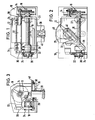
- the pivoting device is shown schematically in side view, an electric motor 12 having a motor shaft 14 which drives a gear 16 is attached to a motor plate or motor housing 10.
- the transmission 16 may be a two-stage gear transmission as shown.
- the unspecified output wheel of the transmission 16 is coupled to a threaded spindle 18 which is mounted in bearings 20, which are only indicated schematically and which are arranged in the motor housing.
- the engine plate or engine housing 10 forms the carrier for the engine, the bearing and the transmission.
- a threaded nut 22 is seated on the threaded spindle 18 and moves along the latter when the threaded spindle 18 rotates.
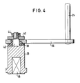
- the pin 24 is fixed to the rocker 26, e.g. riveted, as shown in FIG. 4.
- the threaded nut 22 cooperates with limit switches 30 which are attached to a switch carrier 32, e.g. are screwed on.
- the limit switches 30 are expediently attached to the switch carrier 32 via elongated holes 34, so that the limit switches 30 on the switch carrier 32, which runs parallel to the threaded spindle 18, are adjustable, as a result of which the stroke of the threaded nut 22 on the threaded spindle 18 and thus the stroke of the rocker arm 26 is adjustable.
- the rocker 26 is provided with an elongated hole 36 which is covered with a plastic layer 38, e.g. Delrin who is lined up.
- a square 40 which is part of the control shaft 28, projects into the slot 36 of the rocker 26.
- the square 40 is slidably guided in the slot 36, so that a rotationally fixed coupling is formed between the rocker 26 and the shift shaft 28, but the rocker can move relative to the shift shaft during the pivoting movement.
- the connection between the rocker and the shift shaft is completed by a washer 42, which is placed above the elongated hole 36 on a threaded shoulder of the shift shaft 28, and a nut 44, which is screwed onto this threaded shoulder, as shown in FIG. 4.
- threaded spindle 18 is a rolling spindle and the threaded nut 22 in the form of a recirculating ball nut in order to Reduce friction between the spindle and nut.
- This pivoting movement of the rocker 26 is transmitted via the slot 36 and the square 40 to the switching shaft 28, which also carries out a corresponding pivoting movement and opens or closes the shut-off device, not shown, connected to it.
- the rocker 26 is coupled to the control shaft 28 and thus to the shut-off device in such a way that the latter assumes its closed position in one end position of the rocker 26 and its open position in the other end position of the rocker 26. In this way it is achieved that the torque exerted by the rocker 26 on the shut-off device reaches a maximum in the open position and in the closed position of the shut-off gear, since in the two end positions of the rocker 26 the lever arm for rotating the selector shaft 28, i.e. the distance between the central axis of the pin 24 and the central axis of the control shaft 28 is greatest.
- rocker arm 26 and shift shaft 28 By using a closed elongated hole instead of an open guide at the rear end of the rocker arm, a better connection between rocker arm 26 and shift shaft 28 is achieved and, in particular, the latter is prevented from tilting in the end positions.
- the threaded nut 22 is preferably designed as a recirculating ball nut, but it can also be made of plastic.
- the pivoting device enables the element to be actuated, e.g. a butterfly valve to pivot at least through an angle of 90 °.
Landscapes
- Engineering & Computer Science (AREA)
- General Engineering & Computer Science (AREA)
- Mechanical Engineering (AREA)
- Transmission Devices (AREA)
- Electrically Driven Valve-Operating Means (AREA)
- Mechanically-Actuated Valves (AREA)
Abstract
Description
- Die Erfindung betrifft eine elektromotorisch angetriebene Schwenkvorrichtung, insbesondere zum öffnen und Schließen einer Absperrklappe für eine Rohrleitung mit einem Elektromotor, durch den z.B. über ein Getriebe eine Gewindespindel betätigbar ist, auf der eine Gewindemutter hin- und herbewegbar ist, die über eine Schwinge mit einer Schaltwelle für die Absperrklappe gekoppelt ist.
- Aufgabe der Erfindung ist es, die bisher bekannten Vorrichtungen dieser Art hinsichtlich der Kraftübertragung auf das anzutreibende Element zu verbessern, ferner soll der Platzbedarf und der konstruktive Aufwand verringert werden.
- Nach der Erfindung wird dies dadurch erreicht, daß in den beiden Endlagen der Schwinge das auf die Absperrkläppe ausgeübte Drehmoment ein Maximum erreicht.
- Vorzugsweise ist in den beiden Endlagen der Schwinge der Abstand zwischen dem Anlenkpunkt der Schwinge an der Gewindemutter und der Drehachse der Schaltwelle ein Maximum.
- Die Schwinge ist zweckmäßigerweise an der Gewindemutter drehbar,an der Schaltmuffe dagegen verschiebbar relativ zu dieser angelenkt.
- Vorteilhafterweise ist die Schwinge mit einem Langloch versehen, in welches die Schaltwelle gleitend, aber drehfest mit der Schwinge eingreift. Das Langloch kann mit einem reibungsarmen Kunststoff, z.B. Delrin, ausgekleidet sein.
- Vorteilhafterweise können ferner die Endschalter zur Umsteuerung der Schwenkbewegung der Schwinge an einem Schalterträger mittels Langlöchern verstellbar angebracht sein, wodurch der Hub der Schwinge verändert werden kann.
- Zur Anzeige der Schwingenstellung kann eine mit der Schwinge gekoppelte Anzeigescheibe vorgesehen sein.
- Schließlich ist die Gewindespindel vorzugsweise als Rollspindel und die Gewindemutter als Kugelumlaufmutter ausgeführt, wodurch die Reibungskräfte beträchtlich herabgesetzt werden können.
- Eine beispielsweise Ausführungsform der Erfindung wird nachfolgend anhand der Zeichnung erläutert, in der
- Fig. 1 schematisch eine Vorderansicht der Schwenkvorrichtung zeigt.
- Fig. 2 zeigt schematisch eine Draufsicht auf die Vorrichtung nach Fig. 2;
- Fig. 3 zeigt schematisch eine Seitenansicht auf die Vorrichtung nach Fig. 1 und
- Fig. 4 zeigt teilweise im Schnitt die Schaltwelle mit der Schwinge im Detail.
- In Fig. 1 ist die Schwenkvorrichtung in Seitenansicht schematisch dargestellt, wobei auf einem Motorblech oder Motorgehäuse 10 ein Elektromotor 12 befestigt ist, der eine Motorwelle 14 hat, welche ein Getriebe 16 antreibt. Das Getriebe 16 kann z.B., wie dargestellt, ein zweistufiges Zahnradgetriebe sein.
- Das nicht näher bezeichnete Ausgangsrad des Getriebes 16 ist mit einer Gewindespindel 18 gekoppelt, die in nur schematisch angedeuteten Lagern 20, die im Motorgehäuse angeordnet sind, gelagert ist. Das Motorblech oder Motorgehäuse 10 bildet den Träger für den Motor, das Lager und das Getriebe.
- Auf der Gewindespindel 18 sitzt eine Gewindemutter 22, die bei Drehung der Gewindespindel 18 sich längs der letzteren bewegt.
- Ober einen Zapfen 24 ist die Gewindemutter 22 drehbar mit einer Schwinge 26 gekoppelt, über welche eine Schaltwelle 28 eines hin- und herzuschwenkenden Elements, Z.B. eine Absperrklappe für eine Rohrleitung, betätigbar ist.
- Der Zapfen 24 ist mit der Schwinge 26 fest verbunden, z.B. vernietet, wie Fig. 4 zeigt.
- Die Gewindemutter 22 arbeitet mit Endschaltern 30 zusammen, die an einem Schalterträger 32 befestigt, z.B. angeschraubt sind. Die Befestigung der Endschalter 30 am Schalterträger 32 erfolgt zweckmäßigerweise über Langlöcher 34, so daß die Endschalter 30 am Schalterträger 32, welcher parallel zur Gewindespindel 18 verläuft, verstellbar sind, wodurch der Hub der Gewindemutter 22 auf der Gewindespindel 18 und damit der Hub der Schwinge 26 verstellbar ist.
- Wie Fig. 2 schematisch zeigt, ist die Schwinge 26 mit einem Langloch 36 versehen, das mit einer Kunststoffschicht 38, z.B. Delrin, ausgekleidet ist. In das Langloch 36 der Schwinge 26 ragt ein Zweikant 40 hinein, der Teil der Schaltwelle 28 ist. Der Zweikant 40 ist im Langloch 36 verschiebbar geführt, so daß zwischen der Schwinge 26 und der Schaltwelle 28 eine drehfeste Kopplung gebildet wird, wobei sich aber die Schwinge relativ zur Schaltwelle während der Schwenkbewegung verschieben kann. Die Verbindung zwischen Schwinge und Schaltwelle wird vervollständigt durch eine Scheibe 42, die oberhalb des Langloches 36 auf einen Gewindeansatz der Schaltwelle 28 aufgesetzt ist, sowie eine Mutter 44, die auf diesen Gewindeansatz geschraubt ist, wie Fig. 4 zeigt.
- Die Schaltwelle 28 hat an ihrer Unterseite, wie ebenfalls Fig. 4 zeigt, ein Vierkantloch 46 zur drehfesten Verbindung mit dem zu betätigenden Element. Wie Fig. 3 zeigt, ist mit der Schwinge 26 eine Anzeigescheibe 48 verbunden, welche die jeweilige Stellung der Schwinge und damit des mit ihr gekoppelten Absperrorgans anzeigt.
- Es wird vorgezogen, die Gewindespindel 18 als Rollspindel und die Gewindemutter 22 in Form einer Kugelumlaufmutter auszuführen, um die Reibung zwischen Spindel und Mutter zu reduzieren.
- Die erfindungsgemäße Schwenkvorrichtung arbeitet wie folgt. Wenn der Elektromotor 12 eingeschaltet wird, so treibt er über das Getriebe 16 die Gewindespindel 18 an. Sobald diese sich dreht, beginnt die Gewindemutter 22 auf der Gewindespindel 18 sich in deren Achsrichtung zu bewegen, bis sie auf einen der beiden Endschalter 30 trifft, der durch den Zapfen 24 betätigt wird, wodurch der Motor 12 umgeschaltet und damit auch die Drehrichtung der Gewindespindel 18 umgekehrt wird. Die Gewindemutter 22 läuft dann in umgekehrter Richtung längs der Gewindespindel 18, bis sie auf den anderen Endschalter 30 trifft, wodurch dieser betätigt und dadurch der Motor 12 erneut umgeschaltet wird.
- Die Gewindemutter 22 bewegt sich somit auf der Gewindespindel 18, gesteuert durch die beiden Endschalter 30 hin und her. Bei dieser Hin-und Herbewegung wird die Schwinge 26, die schwenkbar mit der Gewindemutter 22 verbunden ist, mitgenommen, so daß die Schwinge 26 eine Schwenkbewegung ausführt.
- Diese Schwenkbewegung der Schwinge 26 wird über das Langloch 36 und den Zweikant 40 auf die Schaltwelle 28 übertragen, die ebenfalls eine entsprechende Schwenkbewegung ausführt und das mit ihr verbundene, nicht gezeigte Absperrorgan öffnet oder schließt.
- Die Schwinge 26 ist derart mit der Schaltwelle 28 und damit mit dem Absperrorgan gekoppelt, daß das letztere seine geschlossene Stellung in der einen Endstellung der Schwinge 26 und seine geöffnete Stellung in der anderen Endstellung der Schwinge 26 einnimmt. Auf diese Weise wird erreicht, daß das von der Schwinge 26 auf das Absperrorgan ausgeübte Drehmoment in der öffnungsstellung und in der Schließstellung des Absperrorgangs ein Maximum erreicht, da in den beiden Endstellungen der Schwinge 26 der Hebelarm zur Drehung der Schaltwelle 28, d.h. der Abstand zwischen der Mittelachse des Zapfens 24 und der Mittelachse der Schaltwelle 28 am größten ist.
- Während der Schwenkbewegung der Schwinge wird dieser Abstand und damit der Hebelarm verändert und er erreicht sein Minimum in der Mittelstellung der Schwinge zwischen den beiden Endstellungen.
- Wie Fig. 2 zeigt, wird die Schwinge 26 während ihres Schwenkweges im Bereich der Schaltwelle 28 nach rückwärts über diese hinausgeschoben, weil sich während der Schwenkbewegung der Schwinge 26 der obengenannte Hebel oder Abstand von dem Maximalwert in den beiden Endstellungen der Schwinge 26 auf den Minimalwert in der Mittelstellung der Schwinge ändert.
- Trotzdem ist hierzu kein erhöhter Platzbedarf erforderlich, da wegen des Motors und des Getriebes an der Rückseite der Vorrichtung ausreichend Platz für dieses übergreifen der Schwinge zur Verfügung steht.
- An der Vorderseite der Schwinge, d.h. an der Verbindungsstelle der Schwinge 26 und des Zpfens 24 mit der Gewindemutter 22 ist demgegenüber, im Gegensatz zu früheren Schwenkvorrichtungen, kein zusätzlicher Raumbedarf erforderlich, weil die Schwinge an der Gewindemutter drehbar aber im übrigen fest angelenkt ist.
- Durch die Verwendung eines geschlossenen Langloches anstelle einer am hinteren Ende der Schwinge offenen Führung wird ferner eine bessere Verbindung zwischen Schwinge 26 und Schaltwelle 28 als bisher erreicht und insbesondere ein Kippen der letzteren in den Endstellungen verhindert.
- Infolge der Verwendung des reibungsarmen Kunststoffbelages 38 und der langen Führung des Zweikantes 40 im Langloch 36 wird eine beträchtliche Verminderung der Reibung erzielt.
- Die Gewindemutter 22 wird, wie bereits erwähnt, vorzugsweise als Kugelumlaufmutter ausgeführt, sie kann aber auch aus Kunststoff ausgeführt sein. Die Schwenkvorrichtung ermöglicht es, das zu betätigende Element, z.B. eine Absperrklappe, mindestens über einen Winkel von 90° zu schwenken.
Claims (8)
Applications Claiming Priority (3)
| Application Number | Priority Date | Filing Date | Title |
|---|---|---|---|
| DE3615368A DE3615368C2 (de) | 1986-05-06 | 1986-05-06 | Elektromotorisch angetriebene Schwenkvorrichtung |
| DE8612452U DE8612452U1 (de) | 1986-05-06 | 1986-05-06 | Elektromotorisch angetriebene Schwenkvorrichtung |
| DE3615368 | 1986-05-06 |
Publications (3)
| Publication Number | Publication Date |
|---|---|
| EP0244578A2 true EP0244578A2 (de) | 1987-11-11 |
| EP0244578A3 EP0244578A3 (en) | 1988-09-07 |
| EP0244578B1 EP0244578B1 (de) | 1990-08-08 |
Family
ID=40298207
Family Applications (1)
| Application Number | Title | Priority Date | Filing Date |
|---|---|---|---|
| EP87102537A Expired - Lifetime EP0244578B1 (de) | 1986-05-06 | 1987-02-23 | Elektromotorisch angetriebene Schwenkvorrichtung |
Country Status (5)
| Country | Link |
|---|---|
| US (1) | US4715580A (de) |
| EP (1) | EP0244578B1 (de) |
| JP (1) | JP2521278B2 (de) |
| BR (1) | BR8702279A (de) |
| DE (2) | DE3615368C2 (de) |
Cited By (3)
| Publication number | Priority date | Publication date | Assignee | Title |
|---|---|---|---|---|
| GB2241353A (en) * | 1990-01-26 | 1991-08-28 | Weber Srl | Motorized throttle valve |
| CN102554675A (zh) * | 2010-12-08 | 2012-07-11 | 孙长顺 | 调速滑块 |
| US11473694B1 (en) | 2021-05-14 | 2022-10-18 | Spears Manufacturing Co. | Valve operator assembly |
Families Citing this family (11)
| Publication number | Priority date | Publication date | Assignee | Title |
|---|---|---|---|---|
| DE3615368C2 (de) | 1986-05-06 | 1996-01-25 | Fritz Mueller | Elektromotorisch angetriebene Schwenkvorrichtung |
| JPH0711647Y2 (ja) * | 1989-07-27 | 1995-03-22 | アイシン精機株式会社 | ヘツドレスト装置 |
| US4995278A (en) * | 1989-08-04 | 1991-02-26 | Huang Yung C | Car mark emblem display and storage device |
| JP2539688B2 (ja) * | 1989-11-02 | 1996-10-02 | 東芝機械株式会社 | 移動体の早送り速度制御方法 |
| US5052424A (en) * | 1990-07-16 | 1991-10-01 | Eaton Corporation | Electrically operated servo actuator with automatic shut off |
| US6098957A (en) * | 1998-07-31 | 2000-08-08 | Honeywell Inc. | Electro-mechanical torque limiter for valve actuators |
| DE10061184A1 (de) * | 2000-12-07 | 2002-06-13 | Murrplastik Produktionstechnik | Motorventil |
| DE102006043994A1 (de) | 2006-09-19 | 2008-03-27 | GEMÜ Gebrüder Müller GmbH & Co. KG | Motorgesteuerter Schwenkantrieb |
| DE102007001741A1 (de) * | 2007-01-11 | 2008-07-17 | Siemens Ag | Vorrichtung zur linearen Bewegung eines Ventilgliedes |
| US9772046B2 (en) * | 2013-12-05 | 2017-09-26 | Badger Meter, Inc. | Method and apparatus for mounting a control valve positioner |
| JP2018197566A (ja) * | 2017-05-23 | 2018-12-13 | Ntn株式会社 | バルブ用電動アクチュエータおよびバルブ装置 |
Family Cites Families (17)
| Publication number | Priority date | Publication date | Assignee | Title |
|---|---|---|---|---|
| US1033577A (en) * | 1910-11-01 | 1912-07-23 | Faconeisenwalzwerk L Mannstaedt & Cie Ag | Reversing-valve for regenerative furnaces. |
| US2704947A (en) * | 1953-04-30 | 1955-03-29 | Morgan Smith S Co | Manual and automatic valve actuator with declutching unit |
| US3063298A (en) * | 1959-11-09 | 1962-11-13 | Kenneth R Elliott | Operator for rotary valve |
| GB966039A (en) * | 1961-11-24 | 1964-08-06 | Rotork Eng Co Ltd | Improvements in or relating to auxiliary drive units,more particularly for valve actuators |
| GB1064954A (en) * | 1963-05-31 | 1967-04-12 | English Electric Co Ltd | Improvements relating to operating mechanisms for spindle-controlled devices |
| DE1897712U (de) * | 1964-03-14 | 1964-07-30 | Ruhrtal Elek Zitaetsgesellscha | Motorgetriebene stellvorrichtung, insbesondere fuer elektrische schaltgeraete. |
| DE1675986B1 (de) * | 1964-07-31 | 1971-04-08 | Grove Valve & Regulator Co | Betaetigungsvorrichtung fuer Rohrleitungsarmaturen |
| US3575378A (en) * | 1969-06-18 | 1971-04-20 | Pratt Co Henry | Valve operator mechanism |
| US3651711A (en) * | 1970-04-16 | 1972-03-28 | Anderson Greenwood & Co | Shaft rotating device |
| DE2123677C3 (de) * | 1971-05-13 | 1974-07-25 | Research Engineering Co., Houston, Tex. (V.St.A.) | Elektromotorische Antriebsvorrichtung, insbesondere für Ventile |
| JPS4738254U (de) * | 1971-05-21 | 1972-12-27 | ||
| US3774462A (en) * | 1972-04-20 | 1973-11-27 | J Thompson | Valve actuator |
| US3877677A (en) * | 1974-03-06 | 1975-04-15 | Mueller Co | Valve operator for butterfly valves or the like |
| JPS54156228U (de) * | 1978-04-22 | 1979-10-30 | ||
| JPS565879U (de) * | 1979-06-25 | 1981-01-19 | ||
| US4625758A (en) * | 1985-06-28 | 1986-12-02 | Itt Corporation | Valve actuator apparatus |
| DE3615368C2 (de) | 1986-05-06 | 1996-01-25 | Fritz Mueller | Elektromotorisch angetriebene Schwenkvorrichtung |
-
1986
- 1986-05-06 DE DE3615368A patent/DE3615368C2/de not_active Expired - Lifetime
- 1986-05-06 DE DE8612452U patent/DE8612452U1/de not_active Expired
-
1987
- 1987-02-17 US US07/015,222 patent/US4715580A/en not_active Expired - Lifetime
- 1987-02-23 EP EP87102537A patent/EP0244578B1/de not_active Expired - Lifetime
- 1987-02-25 JP JP62042473A patent/JP2521278B2/ja not_active Expired - Lifetime
- 1987-05-05 BR BR8702279A patent/BR8702279A/pt not_active IP Right Cessation
Cited By (3)
| Publication number | Priority date | Publication date | Assignee | Title |
|---|---|---|---|---|
| GB2241353A (en) * | 1990-01-26 | 1991-08-28 | Weber Srl | Motorized throttle valve |
| CN102554675A (zh) * | 2010-12-08 | 2012-07-11 | 孙长顺 | 调速滑块 |
| US11473694B1 (en) | 2021-05-14 | 2022-10-18 | Spears Manufacturing Co. | Valve operator assembly |
Also Published As
| Publication number | Publication date |
|---|---|
| DE8612452U1 (de) | 1986-06-26 |
| DE3615368A1 (de) | 1987-11-12 |
| DE3615368C2 (de) | 1996-01-25 |
| EP0244578B1 (de) | 1990-08-08 |
| EP0244578A3 (en) | 1988-09-07 |
| BR8702279A (pt) | 1988-02-17 |
| JP2521278B2 (ja) | 1996-08-07 |
| JPS62261785A (ja) | 1987-11-13 |
| US4715580A (en) | 1987-12-29 |
Similar Documents
| Publication | Publication Date | Title |
|---|---|---|
| DE4431348C2 (de) | Automatische Schiebetür | |
| EP0244578B1 (de) | Elektromotorisch angetriebene Schwenkvorrichtung | |
| DE2443375C3 (de) | Steuereinrichtung für ein von Hand zu führendes und zu steuerndes Fahrzeug | |
| DE2942006A1 (de) | Schiebedach fuer kraftfahrzeuge | |
| DE68907692T2 (de) | Schiebedachaufbau für ein Fahrzeug. | |
| DE3117040C2 (de) | Betätigungsvorrichtung für ein Kipp- und Schiebedach eines Kraftfahrzeugs oder dergleichen | |
| DE3908293A1 (de) | Scheibenwischervorrichtung | |
| EP0825367A3 (de) | Betätigungseinrichtung für ein Kraftfahrzeuggetriebe | |
| DE3119920C2 (de) | ||
| DE3913480C2 (de) | ||
| DE3520502A1 (de) | Antriebsvorrichtung fuer ventile | |
| DE3707837C2 (de) | ||
| DE4209652C1 (en) | Two directional drive for sunroof panel of motor vehicle - has electromotor coupled to drive pinion on drive shaft via reduction gearing | |
| DE1480678B2 (de) | Fernschalteinrichtung fuer wechselgetriebe von kraftfahrzeugen | |
| DE4433595A1 (de) | Lenkstockschalter als Getriebeschalter mit fixierbarer Neutralstellung | |
| DE2231265A1 (de) | Fussteuervorrichtung, insbesondere fuer zahnaerztliche geraete | |
| DE4131858C2 (de) | ||
| DE19526995A1 (de) | Vorrichtung zum Einsetzen in einen seilzugbetätigten Kraftfahrzeugschalthebel-Gelenkmechanismus | |
| DE69705783T2 (de) | Verbessertes motorisiertes landwirtschaftliches Arbeitsgerät | |
| DE885017C (de) | Kraftheber, insbesondere fuer landwirtschaftliche Zugmaschinen, mit einer durch Motorkraft bewegten Hubspindel | |
| DE69002753T2 (de) | Aufbau eines elektrischen Schiebedaches. | |
| DE69815034T2 (de) | Vorrichtung und Verfahren zur Erlangung eines Betätigungsmomentes | |
| DE3002968A1 (de) | Betaetigungsvorrichtung fuer geschwindigkeitswechselgetriebe von kraftfahrzeugen | |
| DE2846898C2 (de) | Höheneinstellvorrichtung für ein Fahrzeug-Schiebedach | |
| EP0216377B1 (de) | Mechanische Schaltvorrichtung für Wechselgetriebe von Fahrzeugen |
Legal Events
| Date | Code | Title | Description |
|---|---|---|---|
| PUAI | Public reference made under article 153(3) epc to a published international application that has entered the european phase |
Free format text: ORIGINAL CODE: 0009012 |
|
| AK | Designated contracting states |
Kind code of ref document: A2 Designated state(s): CH FR GB IT LI |
|
| PUAL | Search report despatched |
Free format text: ORIGINAL CODE: 0009013 |
|
| AK | Designated contracting states |
Kind code of ref document: A3 Designated state(s): CH FR GB IT LI |
|
| 17P | Request for examination filed |
Effective date: 19880922 |
|
| 17Q | First examination report despatched |
Effective date: 19890728 |
|
| GRAA | (expected) grant |
Free format text: ORIGINAL CODE: 0009210 |
|
| AK | Designated contracting states |
Kind code of ref document: B1 Designated state(s): CH FR GB IT LI |
|
| ET | Fr: translation filed | ||
| ITF | It: translation for a ep patent filed | ||
| GBT | Gb: translation of ep patent filed (gb section 77(6)(a)/1977) | ||
| ITTA | It: last paid annual fee | ||
| PLBE | No opposition filed within time limit |
Free format text: ORIGINAL CODE: 0009261 |
|
| STAA | Information on the status of an ep patent application or granted ep patent |
Free format text: STATUS: NO OPPOSITION FILED WITHIN TIME LIMIT |
|
| 26N | No opposition filed | ||
| REG | Reference to a national code |
Ref country code: GB Ref legal event code: IF02 |
|
| PGFP | Annual fee paid to national office [announced via postgrant information from national office to epo] |
Ref country code: FR Payment date: 20060215 Year of fee payment: 20 |
|
| PGFP | Annual fee paid to national office [announced via postgrant information from national office to epo] |
Ref country code: GB Payment date: 20060221 Year of fee payment: 20 Ref country code: CH Payment date: 20060221 Year of fee payment: 20 |
|
| PGFP | Annual fee paid to national office [announced via postgrant information from national office to epo] |
Ref country code: IT Payment date: 20060228 Year of fee payment: 20 |
|
| PG25 | Lapsed in a contracting state [announced via postgrant information from national office to epo] |
Ref country code: GB Free format text: LAPSE BECAUSE OF EXPIRATION OF PROTECTION Effective date: 20070222 |
|
| REG | Reference to a national code |
Ref country code: GB Ref legal event code: PE20 |
|
| REG | Reference to a national code |
Ref country code: CH Ref legal event code: PL |