EP0244564B1 - Dispositif de protection pour empêcher de forer dans une serrure - Google Patents
Dispositif de protection pour empêcher de forer dans une serrure Download PDFInfo
- Publication number
- EP0244564B1 EP0244564B1 EP87101566A EP87101566A EP0244564B1 EP 0244564 B1 EP0244564 B1 EP 0244564B1 EP 87101566 A EP87101566 A EP 87101566A EP 87101566 A EP87101566 A EP 87101566A EP 0244564 B1 EP0244564 B1 EP 0244564B1
- Authority
- EP
- European Patent Office
- Prior art keywords
- plate
- actuating elements
- stays
- protector
- end parts
- Prior art date
- Legal status (The legal status is an assumption and is not a legal conclusion. Google has not performed a legal analysis and makes no representation as to the accuracy of the status listed.)
- Expired
Links
- 238000005553 drilling Methods 0.000 title claims description 7
- 230000001012 protector Effects 0.000 claims description 8
- 125000006850 spacer group Chemical group 0.000 claims description 7
- 229910000760 Hardened steel Inorganic materials 0.000 claims description 6
- 229910000831 Steel Inorganic materials 0.000 claims description 6
- 239000000919 ceramic Substances 0.000 claims description 6
- 239000010959 steel Substances 0.000 claims description 6
- 210000002105 tongue Anatomy 0.000 claims description 4
- 241000220317 Rosa Species 0.000 claims 2
- 238000009434 installation Methods 0.000 description 28
- 230000001681 protective effect Effects 0.000 description 14
- 230000009993 protective function Effects 0.000 description 2
- 238000003780 insertion Methods 0.000 description 1
- 230000037431 insertion Effects 0.000 description 1
- 238000003754 machining Methods 0.000 description 1
Images

Classifications
-
- E—FIXED CONSTRUCTIONS
- E05—LOCKS; KEYS; WINDOW OR DOOR FITTINGS; SAFES
- E05B—LOCKS; ACCESSORIES THEREFOR; HANDCUFFS
- E05B15/00—Other details of locks; Parts for engagement by bolts of fastening devices
- E05B15/16—Use of special materials for parts of locks
- E05B15/1614—Use of special materials for parts of locks of hard materials, to prevent drilling
Definitions
- the invention relates to a protective device against drilling into the actuating elements of espagnolette fittings for windows, doors or the like.
- a flat plate made of hardened steel, sintered steel, hard ceramic or the like, which can be inserted into the recess of the wing spar on the outside of the actuating elements, the edge contour of which the contour of the installation recess is coordinated, the plate being able to be placed directly against the outer side surface of the installation housing and being supported with a longitudinal edge against the back of the faceplate or a foot part of the installation housing.
- a protective device or a protector of this type for use in connection with locks is already known from GB-A-2 111 583. It is intended to prevent burglars from heighting the window or door sash from the outside drill the actuators and thereby make them accessible for unlawful opening of the windows and doors.
- the invention has for its object to provide a protective device of the generic type that can be properly and safely assigned to the actuators or the installation housing even before the installation of the drive rod fittings, so that the desired protective function is guaranteed in any case while facilitating the striking work.
- the retaining lugs can be formed by tabs or tongues which are bent up from the plane of the plate and which have end parts bent at right angles.
- Another possible design of the protective device according to the invention is characterized by two plates which are congruent in terms of their contours and which are connected to one another at a distance by spacer bolts, one plate consisting of hardened steel, sintered steel, hard ceramic or the like. while the other plate with the spacer bolts forms the retaining lugs and is provided with openings for the rosette fastening screws and the square mandrel of a bearing rosette and an operating handle located therein.
- the drive rod fitting 1 shown in the drawing has a faceplate 2, behind which a drive rod 3 is guided in a longitudinally sliding manner.
- a drive rod 3 At the drive rod 3 there are locking pins 4, one of which can be seen in Fig. 1.
- the locking pins 4 can each be displaced in a longitudinal slot 5 of the faceplate 2.
- the installation housing 6 for actuating elements for example a rotatably mounted pinion 7, is fastened, this or this being or being in engagement with the drive rod 3.
- the actuating elements or the pinion 7 are assigned an operating handle 8 which is rotatably seated in a bearing rosette 9.
- the operating handle 8 can be coupled to the inner square 11 of the pinion 7 or the like via a square mandrel 10, while at the same time the bearing rosette 9 is to be anchored in threaded holes 13 of the installation housing 6 by screws 12, which are only indicated by dash-dotted lines.
- the installation housing 6 is received in an installation recess 14 of the wing spar 15, while the bearing rosette 9 is seated on the end face 16 of this wing spar 15 on the room side.
- a flat plate is inserted into the mounting recess 14 of the wing spar 15 on the side surface of the drilling housing 6 facing away from the bearing rosette 9 17 made of hardened steel, sintered steel, hard ceramic or the like.
- the plate 17 is suitably received by the installation recess 14 of the wing spar 15 and lies directly on the side surface of the installation housing 6.
- the plate 17 With its straight longitudinal edge 18, the plate 17 rests against the back of the faceplate 2 or a foot part 19 of the installation housing 6 that is held in engagement therewith and is thereby held in the installation recess 14.
- the hardened or otherwise resistant to machining plate 17 forms a protective device against illegal drilling of the installation housing 6 or the actuating elements arranged therein (pinion 7). It also protects the engagement area of the square mandrel 10 and the screws 12 for holding the bearing rosette 9 for the operating handle 8.
- the plate 17 can be properly connected to the mounting housing 6 before the insertion of the connecting rod fitting 1 into the mounting recess 14, it is provided with holding projections 20 which protrude at right angles from its side facing the mounting housing 6 and can engage behind support surfaces located on the mounting housing 6 .
- 1 are formed by tabs or tongues which are bent up from the plane of the plate and which have end parts 21 bent at right angles.
- the retaining lugs 20 or tabs or tongues are inserted from behind into slot-like recesses 6a of the installation housing 6, so that their bent end parts 21 can overlap the side surface of the installation housing 6 opposite the plate 17, as is indicated in FIG. 2.
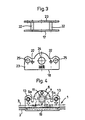
- the protective device against drilling into the installation housing can also consist of two plates 17 and 23 which are congruent in terms of their contours and which are connected to one another by spacers 22 at a distance.
- One plate 17 consists of hardened steel, sintered steel, hard ceramic or the like, while the other plate 23 is provided with passages 25 for the screws 12 for holding the bearing rosette 9 and a further passage 24 for the square mandrel 10 of the operating handle 8.
- This protective device is pushed from behind onto the installation housing 6 of the connecting rod fitting 1 in such a way that the two spacer bolts 22 engage in the slot-like cutouts 6a which are open at the rear, while the two plates 17 and 23 abut the opposite side surfaces of the installation housing 6 come.
- the spacer bolts 22 can also each carry a single thin disk or a flat head, which supports the mounting housing 6 at the edge of the slot-like recesses 6a and thereby holds the plate 17 in the desired position.
Landscapes
- Aiming, Guidance, Guns With A Light Source, Armor, Camouflage, And Targets (AREA)
Claims (3)
Priority Applications (1)
| Application Number | Priority Date | Filing Date | Title |
|---|---|---|---|
| AT87101566T ATE44397T1 (de) | 1986-05-09 | 1987-02-05 | Schutzvorrichtung gegen anbohren. |
Applications Claiming Priority (4)
| Application Number | Priority Date | Filing Date | Title |
|---|---|---|---|
| DE19868612668 DE8612668U1 (de) | 1986-05-09 | 1986-05-09 | Schutzvorrichtung gegen Anbohren |
| DE8612668U | 1986-05-09 | ||
| DE19868625816 DE8625816U1 (de) | 1986-09-26 | 1986-09-26 | Schutzvorrichtung gegen Anbohren |
| DE8625816U | 1986-09-26 |
Publications (2)
| Publication Number | Publication Date |
|---|---|
| EP0244564A1 EP0244564A1 (fr) | 1987-11-11 |
| EP0244564B1 true EP0244564B1 (fr) | 1989-07-05 |
Family
ID=25950862
Family Applications (1)
| Application Number | Title | Priority Date | Filing Date |
|---|---|---|---|
| EP87101566A Expired EP0244564B1 (fr) | 1986-05-09 | 1987-02-05 | Dispositif de protection pour empêcher de forer dans une serrure |
Country Status (2)
| Country | Link |
|---|---|
| EP (1) | EP0244564B1 (fr) |
| DE (1) | DE3760296D1 (fr) |
Families Citing this family (2)
| Publication number | Priority date | Publication date | Assignee | Title |
|---|---|---|---|---|
| DE4317994C1 (de) * | 1993-05-28 | 1994-10-20 | Winkhaus Fa August | Schließzylinder |
| CH704743B1 (de) | 2012-05-09 | 2012-10-15 | August Scherrer | Schutzvorrichtung gegen das Aufbohren von Fenstern und Fenstertüren. |
Family Cites Families (2)
| Publication number | Priority date | Publication date | Assignee | Title |
|---|---|---|---|---|
| DE3033585C2 (de) * | 1980-09-06 | 1984-11-08 | Heinrich 3550 Marburg Sälzer | Schutzvorrichtung für Schlüssellöcher |
| GB2111583A (en) * | 1981-11-28 | 1983-07-06 | Speedcraft Limited | Protector for locks |
-
1987
- 1987-02-05 EP EP87101566A patent/EP0244564B1/fr not_active Expired
- 1987-02-05 DE DE8787101566T patent/DE3760296D1/de not_active Expired
Also Published As
| Publication number | Publication date |
|---|---|
| DE3760296D1 (en) | 1989-08-10 |
| EP0244564A1 (fr) | 1987-11-11 |
Similar Documents
| Publication | Publication Date | Title |
|---|---|---|
| DE3234512C2 (de) | Türschild für ein Türschloß | |
| EP2113624B1 (fr) | Dispositif de fixation de porte ou de fenêtre | |
| DE102017002647B4 (de) | Einbruchsicherung für mindestens einen Flügel eines Fensters oder einer Tür | |
| EP0244564B1 (fr) | Dispositif de protection pour empêcher de forer dans une serrure | |
| DE8710534U1 (de) | Profilschließzylinder mit Axialsicherung | |
| EP0539908A1 (fr) | Gache réglable pour une porte ou une fenêtre | |
| EP3366873B1 (fr) | Sécurité de fenêtre/porte | |
| DE3437563C2 (fr) | ||
| DE202015105909U1 (de) | Einbruchsicherung | |
| EP1918492A2 (fr) | Ferrure pour la fixation d'une poignée sur une porte ou une fenêtre | |
| EP0302005A2 (fr) | Verrou pour jalousie | |
| EP0036480A1 (fr) | Ferrure pour portes entièrement vitrées | |
| EP1801325B1 (fr) | Système de verrouillage | |
| DE202019105897U1 (de) | Drückerlagerung mit einem Tür- oder Fensterdrücker | |
| DE3305209C3 (de) | Türschloß | |
| DE8625816U1 (de) | Schutzvorrichtung gegen Anbohren | |
| DE3406975C2 (fr) | ||
| DE29702743U1 (de) | Schutzbeschlag zur Sicherung des Schloßgesperres einer Tür | |
| EP0589209A2 (fr) | Serrure cylindrique | |
| EP0276379B1 (fr) | Dispositif de fixation pour armatures | |
| DE2106180C3 (de) | Drehstangenschloß | |
| DE202005020123U1 (de) | Schutzvorrichtung für ein Türschloß | |
| DE3729986C2 (de) | Schutzvorrichtung für Zylinderschlösser | |
| CH690306A5 (de) | Einsteckschloss. | |
| DE102017009348B4 (de) | Fenster- & Türsicherung zur nachträglichen Sicherung für mindestens einen Flügel, eines Fensters oder einer Tür |
Legal Events
| Date | Code | Title | Description |
|---|---|---|---|
| PUAI | Public reference made under article 153(3) epc to a published international application that has entered the european phase |
Free format text: ORIGINAL CODE: 0009012 |
|
| AK | Designated contracting states |
Kind code of ref document: A1 Designated state(s): AT BE CH DE FR GB IT LI NL SE |
|
| 17P | Request for examination filed |
Effective date: 19871121 |
|
| 17Q | First examination report despatched |
Effective date: 19880810 |
|
| ITF | It: translation for a ep patent filed | ||
| GRAA | (expected) grant |
Free format text: ORIGINAL CODE: 0009210 |
|
| AK | Designated contracting states |
Kind code of ref document: B1 Designated state(s): AT BE CH DE FR GB IT LI NL SE |
|
| REF | Corresponds to: |
Ref document number: 44397 Country of ref document: AT Date of ref document: 19890715 Kind code of ref document: T |
|
| GBT | Gb: translation of ep patent filed (gb section 77(6)(a)/1977) | ||
| REF | Corresponds to: |
Ref document number: 3760296 Country of ref document: DE Date of ref document: 19890810 |
|
| ET | Fr: translation filed | ||
| PLBI | Opposition filed |
Free format text: ORIGINAL CODE: 0009260 |
|
| 26 | Opposition filed |
Opponent name: FERCO INTERNATIONAL USINE DE FERRURES DE BATIMENT Effective date: 19900105 |
|
| PLBI | Opposition filed |
Free format text: ORIGINAL CODE: 0009260 |
|
| NLR1 | Nl: opposition has been filed with the epo |
Opponent name: FERCO INTERNATIONAL USINE DE FERRURES DE BATIMENT |
|
| 26 | Opposition filed |
Opponent name: ROTO FRANK AKTIENGESELLSCHAFT Effective date: 19900402 Opponent name: FERCO INTERNATIONAL USINE DE FERRURES DE BATIMENT Effective date: 19900105 |
|
| NLR1 | Nl: opposition has been filed with the epo |
Opponent name: ROTO FRANK AKTIENGESELLSCHAFT. |
|
| ITTA | It: last paid annual fee | ||
| PGFP | Annual fee paid to national office [announced via postgrant information from national office to epo] |
Ref country code: SE Payment date: 19930122 Year of fee payment: 7 Ref country code: DE Payment date: 19930122 Year of fee payment: 7 |
|
| PGFP | Annual fee paid to national office [announced via postgrant information from national office to epo] |
Ref country code: GB Payment date: 19930201 Year of fee payment: 7 |
|
| PGFP | Annual fee paid to national office [announced via postgrant information from national office to epo] |
Ref country code: AT Payment date: 19930202 Year of fee payment: 7 |
|
| PGFP | Annual fee paid to national office [announced via postgrant information from national office to epo] |
Ref country code: CH Payment date: 19930203 Year of fee payment: 7 |
|
| PGFP | Annual fee paid to national office [announced via postgrant information from national office to epo] |
Ref country code: FR Payment date: 19930218 Year of fee payment: 7 |
|
| PGFP | Annual fee paid to national office [announced via postgrant information from national office to epo] |
Ref country code: NL Payment date: 19930228 Year of fee payment: 7 |
|
| PGFP | Annual fee paid to national office [announced via postgrant information from national office to epo] |
Ref country code: BE Payment date: 19930329 Year of fee payment: 7 |
|
| RDAG | Patent revoked |
Free format text: ORIGINAL CODE: 0009271 |
|
| STAA | Information on the status of an ep patent application or granted ep patent |
Free format text: STATUS: PATENT REVOKED |
|
| REG | Reference to a national code |
Ref country code: CH Ref legal event code: PL |
|
| 27W | Patent revoked |
Effective date: 19931012 |
|
| GBPR | Gb: patent revoked under art. 102 of the ep convention designating the uk as contracting state |
Free format text: 931012 |
|
| NLR2 | Nl: decision of opposition | ||
| EUG | Se: european patent has lapsed |
Ref document number: 87101566.5 Effective date: 19940420 |
|
| APAH | Appeal reference modified |
Free format text: ORIGINAL CODE: EPIDOSCREFNO |