EP0244485A1 - Führungsanordnung für garnenden - Google Patents
Führungsanordnung für garnenden Download PDFInfo
- Publication number
- EP0244485A1 EP0244485A1 EP85905114A EP85905114A EP0244485A1 EP 0244485 A1 EP0244485 A1 EP 0244485A1 EP 85905114 A EP85905114 A EP 85905114A EP 85905114 A EP85905114 A EP 85905114A EP 0244485 A1 EP0244485 A1 EP 0244485A1
- Authority
- EP
- European Patent Office
- Prior art keywords
- yarn
- take
- tube
- rotary
- rollers
- Prior art date
- Legal status (The legal status is an assumption and is not a legal conclusion. Google has not performed a legal analysis and makes no representation as to the accuracy of the status listed.)
- Granted
Links
Images


Classifications
-
- B—PERFORMING OPERATIONS; TRANSPORTING
- B65—CONVEYING; PACKING; STORING; HANDLING THIN OR FILAMENTARY MATERIAL
- B65H—HANDLING THIN OR FILAMENTARY MATERIAL, e.g. SHEETS, WEBS, CABLES
- B65H67/00—Replacing or removing cores, receptacles, or completed packages at paying-out, winding, or depositing stations
- B65H67/08—Automatic end-finding and material-interconnecting arrangements
- B65H67/086—Preparing supply packages
- B65H67/088—Prepositioning the yarn end into the interior of the supply package
-
- B—PERFORMING OPERATIONS; TRANSPORTING
- B65—CONVEYING; PACKING; STORING; HANDLING THIN OR FILAMENTARY MATERIAL
- B65H—HANDLING THIN OR FILAMENTARY MATERIAL, e.g. SHEETS, WEBS, CABLES
- B65H2701/00—Handled material; Storage means
- B65H2701/30—Handled filamentary material
- B65H2701/31—Textiles threads or artificial strands of filaments
Definitions
- the present invention relates to a yarn end finding device for releasing a bunch winding wound around an end of a spinning bobbin to find a yarn end.
- a bunch winding around which a plurality of yarn ends are wound to prevent the yarn being transported from being released.
- the bobbin In supplying such a spinning bobbin to an automatic winder in the rewinding step, the bobbin is supplied in the state wherein said bunch winding is released.
- a yarn end is released by a suction air while injecting compressed air toward the end of the bobbin in a direction of releasing the yarn.
- a bunch winding is gripped by an opening and closing gripper in the form of scissors and moved relatively in an axial direction of a bobbin to forcibly remove the bunch winding in a pull-out fashion rather than releasing.
- the present invention overcomes the above- described drawbacks and provides a positive yarn end finding device.
- a peripheral surface of a roller which rotates around one axis is pressed against the bunch winding position of a spinning bobbin, and a rotary axis of the roller is inclined in a direction different from the axis of a take-up tube.
- the peripheral surface of the roller which rotates around the axis in a direction different from that of the take-up tube, is pressed against the bunch winding position to provide a force for gradually displacing a yarn layer of the bunch winding wound around the take-up tube toward the axis of the take-up tube, thus easily releasing even the firmly wound bunch winding.
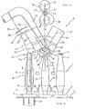
- a spinning bobbin 1 in the state being inserted and stood on a tray 4 formed from a peg 3 projected on a disc-like base plate 2 is transported in a direction as indicated by arrow 9 along a passage 8 formed by guide plates 6 and 7 on a conveyor 5.
- the bobbin tray 4 has an internal space a lower surface of which is open and is formed at a forward end of the peg 3 with an air passage hole 10, so that a yarn end finding portion is transported, in the state being suspended from the upper and within a take-up tube or a bobbin, to a winder.
- the tray passage 8 is formed into a passage curved in a yarn end finding processing station 12 as shown in Fig.
- a bottom guide plate 13 is fixed on the same plane as that of the conveyor 5.
- the bunch winding is released, and in position II, the released yarn end is cut into a given length and attracted into the take-up tube. Therefore, a hole 14 for passage of an attracted air is formed in a guide plate 13 directly below the tray in position II.
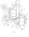
- the yarn end finding device S is composed of rotary rollers 15 and 16 arranged on opposite sides of a bobbin la in the bunch winding releasing position, an attraction pipe 17 for attracting the released yarn end, a cutter 18 for cutting the attracted yarn end into a given length, etc.
- One rotary roller 15 is secured to a rotary shaft 22 through a motor 20 secured to a bracket 19 and a reduction gear 21.
- the roller 15 is formed with a large diameter flange 23, and a small diameter portion 15 is coated with a member having a great coefficient of friction such as rubber.
- the flange portion 23 is provided to stop upward movement of the take-up tube at a.fixed position when the roller 15 is inclined to press against a take-up tube lla.
- the other roller 16 is also secured to a rotary shaft 26 through a motor 24 secured to a bracket and a reduction gear 25, and the roller 16 is formed with a flange portion 27.
- Axes Cl and C2 of the rotary shafts 22 and 26 of the rotary rollers 15 and 16 respectively are inclined at an angle 6 with respect to an axis C3 of the bobbin 1 and are arranged so that they may be urged from both sides of the take-up tube lla. Furthermore, as shown in Figs. 1 and 3, a line 11 connecting between rotational centers of the rotary rollers 15 and 16 is arranged to be slightly deviated through a, and a locating member 28 for locating the upper end of the take-up tube lla is mounted on a bracket of one rotary roller 15 by means of a mounting member not shown.
- the locating member 28 comprises a rotary disc, and the take-up tube lla is supported and positioned at three points, the first and second rotary rollers 15, 16 and the disc 28 so that even when the take-up tube is rotated, the yarn end releasing may be carried out smoothly without deflection of the forward end thereof.
- the disc 28 may be replaced by other non-rotary abutment member which is brought into abutment with a part of the take-up tube.
- a suction pipe 17 is provided above the bobbin la at the yarn end finding position so that an open end 17a of the suction pipe 17 is positioned.
- the suction pipe 17 is formed with a slit 17b for guiding the yarn end to a position of a cutter 18 over a suitable length from the open end 17a.
- the yarn cutter 18 and a guide plate 29 are arranged through a bracket 30 in the yarn running area, on which the yarn travels, along the slit 17b of the suction pipe 17.
- the cutter 18 may be of one internally provided with a sensor for detecting presence or absence of a yarn and a cutter having a movable blade actuated according to a yarn- presence signal of said sensor, or one in which sensor and cutter are separated, which can be suitably selected.
- a bobbin as a yarn end finding miss bobbin is discharged from a normal transporting passage. That is, a movable gate actuated according to the yarn-absence signal of the sensor is provided at the inlet side of a branch passage branched from the transporting passage so that bobbins are portioned out into a yarn end finding success bobbin and a yarn end finding miss bobbin, which have passed through the yarn end finding device, by the opening and closing of the movable gate and are moved to the normal transporting passage and the branch passage, respectively.
- a roller engaging and disengaging device 31 for bringing the take-up tube into engagement with or disengagement from the respective rotary rollers 15 and 16. That is, a rotary solenoid 32 is secured to a bracket 19 on which one roller 15 driving motor 20 is mounted, and a connecting bar 35 is connected between a pivotal lever 34 secured to an output shaft 33 of the rotary solenoid 32 and the other roller 16 driving motor 24 so that the rotary rollers 15 and 16 may be moved close to and away therefrom by utilization of flexture of the brackets 19 and 36 in a lateral direction.
- brackets carrying thereon the rotary rollers 15 and 16 may be supported pivotably within the horizontal plane to thereby engage and disengage the rollers 15 and 16.
- the brackets 19 and 36 are flexed in the direction in which the rollers are moved away from each other, whilst when moved in a direction as indicated at arrow 38, the brackets 19 and 36 are flexed in a direction in which the rollers 15 and 16 are moved close to each other.
- compressed air injection nozzles 39 and 40 provided on both sides below the bobbin make it possible to effect yarn end finding having no top bunch and with a yarn end attached to a yarn layer surface Sf of the spinning bobbin la.
- the nozzles 39 and 40 are arranged so that they are inclined toward the surface of the yarn end and air may be injected in a direction of releasing the yarn end.
- the spinning bobbin 1 having a top bunch Yl in the state being inserted and stood on the bobbin tray 4 is transported on the conveyor 5 in a direction as indicated at arrow 9, and the bobbin 1 reaches the bunch winding releasing position I, the bobbin once stops.
- the rollers 15 and 16 is pressed against the take-up tube lla by the activation of the rotatary solenoid 32 shown in Fig. 2.
- the rotary rollers 15 and 16 are already in rotation by the drive of the motors 20 and 24, and also the suctioning of the suction pipe 17 and the air injection from the nozzles 39 and 40 are being carried out.
- the take-up tube When the peripheral surfaces of the inclined rotary rollers 15 and 16 are pressed against the bunch winding position of the take-up tube, the take-up tube is rotated in a direction in which the yarn end is released by the component of the turning force of the rollers 15 and 16, the force exerts on the yarn of the bunch winding to raise the latter axially upwardly of the take-up tube, and the take-up tube lla has a tapered surface to be narrowed toward the.upper forward end, and therefore the yarn of the bunch winding is easily released and disengaged upwardly from the take-up tube lla, whereby the yarn is suctioned or attracted by the suction pipe 17.
- the released and suctioned yarn end moves along the slit llb of the suction pipe 17, and guided toward the cutter device 18 while being guided by the guide plate 29 of Figs. 1 and 2.
- the yarn Y2 positioned between the slit end 17c of the suction pipe 17 and the bobbin la is not yet arrived at a predetermined position of the cutter 18, and when the bobbin la arrives at the yarn end suction position II of Figs. 1 and 5, the yarn Y3 moves into the groove 18a of the cutter device to insure the presence of the yarn by the sensor encased within the cutter, whereby the cutter is actuated to cut the yarn at the cutter position.
- the cut end of the yarn on the side of the suction pipe 17 of the cut yarn is suctioned into the suction pipe 17 for removal.
- the yarn end on the bobbin lb is suctioned into the take-up tube from the upper end of the take-up pipe llb by the inject effect resulting from the suction air of the suction pipe 41 below the tray 4 in Fig. 1, and the yarn end of a fixed length assumes a state hung down into the take-up pipe as shown by the dash-dotted contour lines Y4 to terminate the yarn end finding operation.
- the guide member 43 at the yarn end suction position shown in Figs. 1 and 4 is provided for the contact thereof with the upper end of the take-up tube 11 of the bobbin to prevent deflection of the upper end of the bobbin, i.e., for locating of a bobbin when the cut yarn end is suctioned, and for locating of a yarn positioned between the cutter 18 and the bobbin lb, so that the cut yarn-end may be positively taken into the take-up tube llc.
- the guide member 43 is formed from a plate or a wire.
- a bunch winding wound about the spinning bobbin may be released by the yarn end- finding device according to the present invention to thereby positively release the bunch winding without damaging the surface of the take-up tube.
- the releasing of the bunch winding according to the present invention may be carried out while carrying the spinning bobbin on the transporting medium such as a tray, the operation is quickly accomplished and in addition the entire system may be advantageously automated.
Landscapes
- Engineering & Computer Science (AREA)
- Textile Engineering (AREA)
- Replacing, Conveying, And Pick-Finding For Filamentary Materials (AREA)
- Spinning Or Twisting Of Yarns (AREA)
- Guides For Winding Or Rewinding, Or Guides For Filamentary Materials (AREA)
Applications Claiming Priority (1)
| Application Number | Priority Date | Filing Date | Title |
|---|---|---|---|
| PCT/JP1985/000574 WO1987002342A1 (fr) | 1985-10-15 | 1985-10-15 | Appareil permettant de faire sortir l'extremite d'un fil |
Publications (3)
| Publication Number | Publication Date |
|---|---|
| EP0244485A1 true EP0244485A1 (de) | 1987-11-11 |
| EP0244485A4 EP0244485A4 (de) | 1989-02-02 |
| EP0244485B1 EP0244485B1 (de) | 1992-06-17 |
Family
ID=13846599
Family Applications (1)
| Application Number | Title | Priority Date | Filing Date |
|---|---|---|---|
| EP85905114A Expired EP0244485B1 (de) | 1985-10-15 | 1985-10-15 | Führungsanordnung für garnenden |
Country Status (4)
| Country | Link |
|---|---|
| US (1) | US4880176A (de) |
| EP (1) | EP0244485B1 (de) |
| DE (1) | DE3586248T2 (de) |
| WO (1) | WO1987002342A1 (de) |
Cited By (3)
| Publication number | Priority date | Publication date | Assignee | Title |
|---|---|---|---|---|
| EP0347535A1 (de) * | 1988-06-24 | 1989-12-27 | W. SCHLAFHORST AG & CO. | Verfahren und Einrichtung zum pneumatischen Erfassen und Überkopfabziehen des Fadenendes eines Kopses |
| EP0463443A3 (en) * | 1990-06-15 | 1992-01-22 | W. Schlafhorst Ag & Co. | Device for positioning of bobbins placed on independent individual carriers and turning them around their vertical axis |
| CN111717730A (zh) * | 2019-03-22 | 2020-09-29 | 卓郎纺织解决方案两合股份有限公司 | 筒管准备方法 |
Families Citing this family (2)
| Publication number | Priority date | Publication date | Assignee | Title |
|---|---|---|---|---|
| JP2541841B2 (ja) * | 1988-06-08 | 1996-10-09 | 村田機械株式会社 | 糸端の口出し装置 |
| CN111891836B (zh) * | 2020-07-17 | 2022-03-04 | 青岛宏大纺织机械有限责任公司 | 一种托盘式络筒机及络筒生产方法 |
Family Cites Families (13)
| Publication number | Priority date | Publication date | Assignee | Title |
|---|---|---|---|---|
| US3108618A (en) * | 1960-03-03 | 1963-10-29 | Toyoda Automatic Loom Works | Bunch remover |
| US3236464A (en) * | 1962-02-03 | 1966-02-22 | Reiners Walter | Device for removing a starting length of yarn from a textile coil |
| CH411653A (de) * | 1963-04-05 | 1966-04-15 | Reiners Walter Dr Ing | Verfahren und Vorrichtung zum Vorbereiten des Abspulvorganges von Spulen |
| GB1091249A (en) * | 1963-12-21 | 1967-11-15 | Reiners Walter | Method and apparatus for feeding supply packages to the winding stations of a thread winding machine |
| GB1158707A (en) | 1965-10-20 | 1969-07-16 | Murata Machinery Co Ltd | An Automatic Cop Supplying Method and Apparatus |
| DE1560574A1 (de) * | 1966-02-17 | 1970-12-10 | Reiners Walter Dr Ing | Vorrichtung zum Freilegen des in der Ober- oder Unterwindung festgelegten Fadenanfanges von Ablaufkopsen |
| US3381908A (en) * | 1966-11-15 | 1968-05-07 | Gojo Factory Shimadzu Seisakus | Automatic cop feeder for a winding machine |
| US3897022A (en) * | 1970-05-18 | 1975-07-29 | Savio Spa | Eliminate tail-ends of yarn and to pick up the end of the end of the wound yarn |
| IT997474B (it) * | 1973-05-04 | 1975-12-30 | Savio Spa | Dispositivo per la ricerca l estrazione ed il posizionamento temporale del bandolo nelle spole |
| DE2423493C2 (de) * | 1974-05-15 | 1983-03-24 | W. Schlafhorst & Co, 4050 Mönchengladbach | Vorrichtung zum pneumatischen Ablösen des Fadenfangs an rotierenden Textilspulen |
| JPS5969372A (ja) * | 1982-10-13 | 1984-04-19 | Murata Mach Ltd | 糸端の口出し装置 |
| JPS6112936A (ja) * | 1984-06-27 | 1986-01-21 | Murao Boki Kk | 精紡管糸の口糸引き出し装置 |
| JPS6260781A (ja) * | 1985-09-10 | 1987-03-17 | Murata Mach Ltd | 糸端の口出し方法 |
-
1985
- 1985-10-15 EP EP85905114A patent/EP0244485B1/de not_active Expired
- 1985-10-15 US US07/066,419 patent/US4880176A/en not_active Expired - Fee Related
- 1985-10-15 WO PCT/JP1985/000574 patent/WO1987002342A1/ja not_active Ceased
- 1985-10-15 DE DE8585905114T patent/DE3586248T2/de not_active Expired - Fee Related
Cited By (3)
| Publication number | Priority date | Publication date | Assignee | Title |
|---|---|---|---|---|
| EP0347535A1 (de) * | 1988-06-24 | 1989-12-27 | W. SCHLAFHORST AG & CO. | Verfahren und Einrichtung zum pneumatischen Erfassen und Überkopfabziehen des Fadenendes eines Kopses |
| EP0463443A3 (en) * | 1990-06-15 | 1992-01-22 | W. Schlafhorst Ag & Co. | Device for positioning of bobbins placed on independent individual carriers and turning them around their vertical axis |
| CN111717730A (zh) * | 2019-03-22 | 2020-09-29 | 卓郎纺织解决方案两合股份有限公司 | 筒管准备方法 |
Also Published As
| Publication number | Publication date |
|---|---|
| EP0244485B1 (de) | 1992-06-17 |
| WO1987002342A1 (fr) | 1987-04-23 |
| DE3586248T2 (de) | 1993-01-28 |
| DE3586248D1 (de) | 1992-07-23 |
| US4880176A (en) | 1989-11-14 |
| EP0244485A4 (de) | 1989-02-02 |
Similar Documents
| Publication | Publication Date | Title |
|---|---|---|
| US4535945A (en) | Method and device for locating and holding a thread end | |
| US4278489A (en) | Web splicing apparatus | |
| US4616789A (en) | Yarn end readying device in winder | |
| JPH055746B2 (de) | ||
| US5950957A (en) | Bobbin winding unit of a textile machine for producing cross-wound bobbins | |
| JP2702022B2 (ja) | ウエブリールの自動交換装置 | |
| EP0244485B1 (de) | Führungsanordnung für garnenden | |
| JP2006193333A (ja) | 綾巻きパッケージを製作する繊維機械の作業位置の糸捕集ノズルにおける負圧を制御するための装置 | |
| US6298647B1 (en) | Yarn-connecting device for a cheese-producing textile machine | |
| US5511734A (en) | Method and apparatus for severing the free yarn end of a yarn reserve winding | |
| JPS6270178A (ja) | 糸端の口出し装置 | |
| US4878629A (en) | Reserve winding of yarn on a tube of a cross-wound bobbin and method and appartus of forming same | |
| EP1277683B1 (de) | Verfahren und Vorrichtung zum Aufnehmen von Material | |
| CN108423493A (zh) | 一种纱管线头捕捉装置及捕捉方法 | |
| EP1236668B1 (de) | Verfahren zum Anlegen eines Garnes an eine Spulhülse in einer automatischen Aufwickelmaschine und automatische Aufwickelmaschine | |
| KR920001806B1 (ko) | 정방관사의 구사 인출장치 | |
| JP2702021B2 (ja) | ウエブリールのウエブ引出し装置 | |
| JP2695373B2 (ja) | 玉揚げ装置 | |
| US5363637A (en) | Method of threading in a false twisting machine and an apparatus for carrying out the same | |
| JPH0251835B2 (de) | ||
| JP2009084023A (ja) | 繊維機械 | |
| JP2656692B2 (ja) | 糸条パッケ−ジの糸端取出方法及び装置 | |
| JPS5842107B2 (ja) | ロ−タリマガジンヘノカンシキヨウキユウツツ | |
| JP2872598B2 (ja) | 糸条パッケージの糸端取り出し方法及びその装置 | |
| JPH10259527A (ja) | 糸条巻取機の糸掛け装置 |
Legal Events
| Date | Code | Title | Description |
|---|---|---|---|
| PUAI | Public reference made under article 153(3) epc to a published international application that has entered the european phase |
Free format text: ORIGINAL CODE: 0009012 |
|
| 17P | Request for examination filed |
Effective date: 19870611 |
|
| AK | Designated contracting states |
Kind code of ref document: A1 Designated state(s): DE IT |
|
| A4 | Supplementary search report drawn up and despatched |
Effective date: 19890202 |
|
| 17Q | First examination report despatched |
Effective date: 19900828 |
|
| GRAA | (expected) grant |
Free format text: ORIGINAL CODE: 0009210 |
|
| ITF | It: translation for a ep patent filed | ||
| AK | Designated contracting states |
Kind code of ref document: B1 Designated state(s): DE IT |
|
| REF | Corresponds to: |
Ref document number: 3586248 Country of ref document: DE Date of ref document: 19920723 |
|
| PLBE | No opposition filed within time limit |
Free format text: ORIGINAL CODE: 0009261 |
|
| STAA | Information on the status of an ep patent application or granted ep patent |
Free format text: STATUS: NO OPPOSITION FILED WITHIN TIME LIMIT |
|
| 26N | No opposition filed | ||
| PGFP | Annual fee paid to national office [announced via postgrant information from national office to epo] |
Ref country code: DE Payment date: 19941206 Year of fee payment: 10 |
|
| PG25 | Lapsed in a contracting state [announced via postgrant information from national office to epo] |
Ref country code: DE Effective date: 19960702 |