EP0243952B1 - A method for manufacturing and reinforcing a catalytic unit intended for purifying exhaust gases - Google Patents
A method for manufacturing and reinforcing a catalytic unit intended for purifying exhaust gases Download PDFInfo
- Publication number
- EP0243952B1 EP0243952B1 EP87106249A EP87106249A EP0243952B1 EP 0243952 B1 EP0243952 B1 EP 0243952B1 EP 87106249 A EP87106249 A EP 87106249A EP 87106249 A EP87106249 A EP 87106249A EP 0243952 B1 EP0243952 B1 EP 0243952B1
- Authority
- EP
- European Patent Office
- Prior art keywords
- catalytic unit
- unit
- central shaft
- secured
- shaft
- Prior art date
- Legal status (The legal status is an assumption and is not a legal conclusion. Google has not performed a legal analysis and makes no representation as to the accuracy of the status listed.)
- Expired
Links
Images

Classifications
-
- F—MECHANICAL ENGINEERING; LIGHTING; HEATING; WEAPONS; BLASTING
- F01—MACHINES OR ENGINES IN GENERAL; ENGINE PLANTS IN GENERAL; STEAM ENGINES
- F01N—GAS-FLOW SILENCERS OR EXHAUST APPARATUS FOR MACHINES OR ENGINES IN GENERAL; GAS-FLOW SILENCERS OR EXHAUST APPARATUS FOR INTERNAL-COMBUSTION ENGINES
- F01N3/00—Exhaust or silencing apparatus having means for purifying, rendering innocuous, or otherwise treating exhaust
- F01N3/08—Exhaust or silencing apparatus having means for purifying, rendering innocuous, or otherwise treating exhaust for rendering innocuous
- F01N3/10—Exhaust or silencing apparatus having means for purifying, rendering innocuous, or otherwise treating exhaust for rendering innocuous by thermal or catalytic conversion of noxious components of exhaust
- F01N3/24—Exhaust or silencing apparatus having means for purifying, rendering innocuous, or otherwise treating exhaust for rendering innocuous by thermal or catalytic conversion of noxious components of exhaust characterised by constructional aspects of converting apparatus
- F01N3/28—Construction of catalytic reactors
- F01N3/2803—Construction of catalytic reactors characterised by structure, by material or by manufacturing of catalyst support
- F01N3/2807—Metal other than sintered metal
- F01N3/281—Metallic honeycomb monoliths made of stacked or rolled sheets, foils or plates
-
- B—PERFORMING OPERATIONS; TRANSPORTING
- B01—PHYSICAL OR CHEMICAL PROCESSES OR APPARATUS IN GENERAL
- B01J—CHEMICAL OR PHYSICAL PROCESSES, e.g. CATALYSIS OR COLLOID CHEMISTRY; THEIR RELEVANT APPARATUS
- B01J35/00—Catalysts, in general, characterised by their form or physical properties
- B01J35/50—Catalysts, in general, characterised by their form or physical properties characterised by their shape or configuration
- B01J35/56—Foraminous structures having flow-through passages or channels, e.g. grids or three-dimensional monoliths
-
- F—MECHANICAL ENGINEERING; LIGHTING; HEATING; WEAPONS; BLASTING
- F01—MACHINES OR ENGINES IN GENERAL; ENGINE PLANTS IN GENERAL; STEAM ENGINES
- F01N—GAS-FLOW SILENCERS OR EXHAUST APPARATUS FOR MACHINES OR ENGINES IN GENERAL; GAS-FLOW SILENCERS OR EXHAUST APPARATUS FOR INTERNAL-COMBUSTION ENGINES
- F01N2260/00—Exhaust treating devices having provisions not otherwise provided for
- F01N2260/18—Exhaust treating devices having provisions not otherwise provided for for improving rigidity, e.g. by wings, ribs
-
- F—MECHANICAL ENGINEERING; LIGHTING; HEATING; WEAPONS; BLASTING
- F01—MACHINES OR ENGINES IN GENERAL; ENGINE PLANTS IN GENERAL; STEAM ENGINES
- F01N—GAS-FLOW SILENCERS OR EXHAUST APPARATUS FOR MACHINES OR ENGINES IN GENERAL; GAS-FLOW SILENCERS OR EXHAUST APPARATUS FOR INTERNAL-COMBUSTION ENGINES
- F01N2330/00—Structure of catalyst support or particle filter
- F01N2330/02—Metallic plates or honeycombs, e.g. superposed or rolled-up corrugated or otherwise deformed sheet metal
- F01N2330/04—Methods of manufacturing
-
- Y—GENERAL TAGGING OF NEW TECHNOLOGICAL DEVELOPMENTS; GENERAL TAGGING OF CROSS-SECTIONAL TECHNOLOGIES SPANNING OVER SEVERAL SECTIONS OF THE IPC; TECHNICAL SUBJECTS COVERED BY FORMER USPC CROSS-REFERENCE ART COLLECTIONS [XRACs] AND DIGESTS
- Y10—TECHNICAL SUBJECTS COVERED BY FORMER USPC
- Y10S—TECHNICAL SUBJECTS COVERED BY FORMER USPC CROSS-REFERENCE ART COLLECTIONS [XRACs] AND DIGESTS
- Y10S55/00—Gas separation
- Y10S55/30—Exhaust treatment
-
- Y—GENERAL TAGGING OF NEW TECHNOLOGICAL DEVELOPMENTS; GENERAL TAGGING OF CROSS-SECTIONAL TECHNOLOGIES SPANNING OVER SEVERAL SECTIONS OF THE IPC; TECHNICAL SUBJECTS COVERED BY FORMER USPC CROSS-REFERENCE ART COLLECTIONS [XRACs] AND DIGESTS
- Y10—TECHNICAL SUBJECTS COVERED BY FORMER USPC
- Y10T—TECHNICAL SUBJECTS COVERED BY FORMER US CLASSIFICATION
- Y10T29/00—Metal working
- Y10T29/49—Method of mechanical manufacture
- Y10T29/49345—Catalytic device making
Definitions
- the present invention relates to a method for manufacturing and reinforcing a catalytic unit used for the purification of exhaust gases, by coating a corrugated foilband (2) and a straight foil band (3) with a support material layer and a catalyst layer, securing said foilbands (2, 3) to a central shaft (4) and winding said foilbands (2, 3), placed one on top of the other, around a central shaft (4) thereby forming a helical catalytic unit (1) of desired size.
- Such a unit is known previously from, for example, GB patent 2 069 364.
- the unit is first made from uncoated foil bands, and at both or one of the ends of the unit there are welded one or several seams the purpose of which is to prevent axial movement of the helical foil bands in relation to one another.
- the catalytic unit cannot be coated with a support material and a catalytic material until after the welding, since the support material lowers the electric conductivity and prevents the flow of current during welding.
- the support material When the support material is added to a complete unit, it does not spread evenly but accumulates in the cavities formed by the meeting points of the foils and collects in itself the actual catalyst, in which case the catalyst material will not be used effectively, a factor which for its part increases the costs and lowers the efficiency.
- the seams produced do not necessarily withstand the stresses the unit is subjected to during use.
- DE Patent 2924592 discloses a method for making a catalytic unit, in which method an uncoated corrugated foil band and an uncoated straight foil band are secured together by brazing. This method has a disadvantage in that in connection with the brazing it is necessary to use high temperatures, which results in the weakening of the structure and a deterioration of the surface.
- the catalytic unit can be coated until after the foil bands have been secured together.
- the brazing is difficult to carry out.
- FR-A-2 214 818 discloses a further method for making a catalytic unit.
- a corrugated foil band and a straight foil band are coated with a catalytically active metal, which is oxidized after it is coated to form a supported catalyst layer.
- a metal oxide may be coated directly on the foilbands.
- the foil bands placed one on top of the other are wound around a central shaft to form a helical unit.
- the helical unit is placed inside a tube and thereafter secured to the tube, e. g. by welding or brazing.
- Crosspieces are arranged at the ends of the tube to prevent axial movement of the helical unit inside the retaining tube.
- the object of the present invention is to provide a method for making and reinforcing a catalytic unit, a method which does not have the disadvantages of previously known methods. What is more, the invention is to provide a method by way of which it is possible to stabilize the shape of the catalytic unit, using simple means.
- this is achieved in that after winding the foilbands rigid end supports are secured to the ends of the shaft in such a way that they press somewhat to inside the unit, thereby preventing axial movement of the foils in relation to each other.
- a catalytic unit which keeps its shape even when subjected to great stress.
- the system according to the invention prevents the movement and rubbing of the foils against each other, which could cause the catalyst layer to be rubbed off and, furthermore the channels to be clogged as the unit is twisted.
- both the corrugated foil band and the straight foil band are coated first with the support material and then with the catalyst material. Thereafter the foil bands, placed one on top of the other, are secured to the central shaft which serves as the rotation shaft at the manufacturing stage of the catalytic unit.
- the central shaft is a thin rod, preferably slit at both ends, which helps the securing of the shaft to the rotating device.
- the slits at the ends of the shaft may be parallel or may run in different directions, for example be perpendicular to each other.
- the rigid end supports preferably have at maximum the length of the diameter of the unit.
- the foil bands are cut and their ends are secured to the unit.
- the unit is detached from the rotating device, the shaft remaining as a support shaft inside the catalytic unit, and transverse end supports are secured to the ends of the shaft.
- the end supports should preferably have the length of the diameter of the catalytic unit so that the catalytic unit becomes a rigid piece which retains its shape.
- the end supports are pressed into slits preferably located at the ends of the shaft, in such a way that the supports press about 1-3 mm to inside the unit, preventing the movement of the foil bands in relation to each other. Thereafter, the end supports are secured firmly to the ends of the shaft, for example by welding. In this case only the ends of the shaft are exposed to the heat caused by the welding, and so the heat will not damage the catalytic unit.
- an end support can be made up of two or several supports placed crosswise and fitted into a slit of a suitable shape formed at the end of the shaft.
- An end support can be secured to the central shaft also in some manner other than that described above, for example by drilling through the center of gravity of the end support a hole into which the end of the central shaft is fitted and secured. Except by welding, the end support can also be secured by, for example fitting a cotter pin into a hole drilled transversely through the end of the shaft after the shaft has been fitted into the hole formed in the end support.
- the central shaft and the end supports are preferably made of fire-resistant steel.
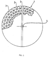
- Figure 1 depicts an end view of a catalytic unit according to the invention
- Figure 2 depicts a side view of a preferred embodiment of the invention.
Landscapes
- Chemical & Material Sciences (AREA)
- Chemical Kinetics & Catalysis (AREA)
- Engineering & Computer Science (AREA)
- Mechanical Engineering (AREA)
- Organic Chemistry (AREA)
- Health & Medical Sciences (AREA)
- Toxicology (AREA)
- Combustion & Propulsion (AREA)
- Materials Engineering (AREA)
- General Engineering & Computer Science (AREA)
- Catalysts (AREA)
- Exhaust Gas After Treatment (AREA)
- Exhaust Gas Treatment By Means Of Catalyst (AREA)
- Medicines Containing Antibodies Or Antigens For Use As Internal Diagnostic Agents (AREA)
- Nitrogen And Oxygen Or Sulfur-Condensed Heterocyclic Ring Systems (AREA)
- Ultra Sonic Daignosis Equipment (AREA)
Priority Applications (1)
| Application Number | Priority Date | Filing Date | Title |
|---|---|---|---|
| AT87106249T ATE47200T1 (de) | 1986-04-29 | 1987-04-29 | Herstellung und verstaerkungsverfahren einer katalytischen einheit zum reinigen von abgasen. |
Applications Claiming Priority (2)
| Application Number | Priority Date | Filing Date | Title |
|---|---|---|---|
| FI861801 | 1986-04-29 | ||
| FI861801A FI74523C (fi) | 1986-04-29 | 1986-04-29 | Framstaellnings- och befaestningsfoerfarande av en katalytcell avsedd foer rening av avgas. |
Publications (2)
| Publication Number | Publication Date |
|---|---|
| EP0243952A1 EP0243952A1 (en) | 1987-11-04 |
| EP0243952B1 true EP0243952B1 (en) | 1989-10-11 |
Family
ID=8522531
Family Applications (1)
| Application Number | Title | Priority Date | Filing Date |
|---|---|---|---|
| EP87106249A Expired EP0243952B1 (en) | 1986-04-29 | 1987-04-29 | A method for manufacturing and reinforcing a catalytic unit intended for purifying exhaust gases |
Country Status (8)
| Country | Link |
|---|---|
| US (2) | US4741082A (fi) |
| EP (1) | EP0243952B1 (fi) |
| AT (1) | ATE47200T1 (fi) |
| AU (1) | AU589512B2 (fi) |
| CA (1) | CA1273481A (fi) |
| DE (1) | DE3760750D1 (fi) |
| ES (1) | ES2011034B3 (fi) |
| FI (1) | FI74523C (fi) |
Families Citing this family (31)
| Publication number | Priority date | Publication date | Assignee | Title |
|---|---|---|---|---|
| DE3634235C1 (de) * | 1986-10-08 | 1988-03-31 | Sueddeutsche Kuehler Behr | Matrix fuer einen katalytischen Reaktor zur Abgasreinigung |
| DE3738537A1 (de) * | 1987-11-13 | 1989-06-01 | Sueddeutsche Kuehler Behr | Verfahren und vorrichtung zur herstellung eines traegerkoerpers fuer einen katalytischen reaktor |
| US4782570A (en) * | 1987-11-16 | 1988-11-08 | General Motors Corporation | Fabrication and assembly of metal catalytic converter catalyst substrate |
| FI78161C (fi) * | 1987-11-16 | 1989-06-12 | Kemira Oy | Foerfarande foer framstaellning och foerstaerkning av en katalytcellstruktur anvaendbar foer rening av avgaser. |
| DE8816514U1 (de) * | 1988-04-25 | 1989-10-26 | Emitec Gesellschaft für Emissionstechnologie mbH, 5204 Lohmar | Elektrisch beheizbarer Katalysator-Trägerkörper |
| US5163291A (en) * | 1988-08-13 | 1992-11-17 | Usui Kokusai Sangyo Kabushiki Kaisha | Metal-made carrier body for exhaust gas cleaning catalyst |
| US4928485A (en) * | 1989-06-06 | 1990-05-29 | W. R. Grace & Co.,-Conn. | Metallic core member for catalytic converter and catalytic converter containing same |
| JPH04136412A (ja) * | 1990-09-28 | 1992-05-11 | Nissan Motor Co Ltd | ハニカム触媒コンバータの加熱装置 |
| GB2250215A (en) * | 1990-11-29 | 1992-06-03 | Rover Group | A catalytic converter |
| JP3366914B2 (ja) * | 1991-07-04 | 2003-01-14 | 松本鋼管株式会社 | 触媒メタル担体とその製造方法 |
| US5554342A (en) * | 1991-12-20 | 1996-09-10 | Toyota Jidosha Kabushiki Kaisha | Electrical heating type catalytic device |
| JP2568751Y2 (ja) * | 1992-02-28 | 1998-04-15 | 三恵技研工業株式会社 | 排気浄化装置 |
| JP3222542B2 (ja) * | 1992-04-24 | 2001-10-29 | 株式会社デンソー | 金属製触媒担体 |
| US5298046A (en) * | 1993-01-06 | 1994-03-29 | Minnesota Mining And Manufacturing Company | Diesel particulate filter element and filter |
| US5546746A (en) * | 1993-02-04 | 1996-08-20 | W. R. Grace & Co.-Conn. | Core element useful in a combined electrically heatable and light-off converter |
| DE4338327A1 (de) * | 1993-11-10 | 1995-05-11 | Witte Alexander Dr Ing | Abgaskatalysator und Verfahren zur Herstellung eines solchen für ein Kraftfahrzeug |
| WO1995020434A1 (en) * | 1994-01-27 | 1995-08-03 | Engelhard Corporation | Process for recovering catalyst supports |
| US5431886A (en) * | 1994-04-08 | 1995-07-11 | W. R. Grace & Co.-Conn. | Combined electrically heatable converter |
| US5632961A (en) * | 1995-01-10 | 1997-05-27 | W. R. Grace & Co.-Conn. | Reinforcing web for a multicellular converter |
| US5721188A (en) * | 1995-01-17 | 1998-02-24 | Engelhard Corporation | Thermal spray method for adhering a catalytic material to a metallic substrate |
| JP3755008B2 (ja) * | 1995-05-22 | 2006-03-15 | 株式会社日本自動車部品総合研究所 | 排ガス浄化用金属製触媒担体の製造方法 |
| DE19523532A1 (de) * | 1995-06-28 | 1997-01-02 | Emitec Emissionstechnologie | Katalysatoranordnung mit zwei- oder mehrsträngiger Abgasführung |
| GB2320692B (en) * | 1996-12-27 | 1999-01-13 | Emitec Emissionstechnologie | Catalytic converter arrangement |
| US20010033812A1 (en) * | 1997-06-24 | 2001-10-25 | Haruhiko Nagura | Catalyst converter |
| US20020128151A1 (en) * | 1998-05-01 | 2002-09-12 | Michael P. Galligan | Catalyst members having electric arc sprayed substrates and methods of making the same |
| DE19922358C1 (de) * | 1999-05-14 | 2001-01-25 | Helmut Swars | Wabenkörper |
| DE19922356C2 (de) * | 1999-05-14 | 2001-06-13 | Helmut Swars | Wabenkörper |
| RU2151308C1 (ru) * | 1999-07-06 | 2000-06-20 | Центральный научно-исследовательский автомобильный и автомоторный институт | Нейтрализатор |
| US6852141B2 (en) * | 2001-06-06 | 2005-02-08 | Donaldson Company, Inc. | Filter element having center piece and methods |
| EP2845640B1 (en) | 2013-09-06 | 2018-10-24 | Vysoké Ucení Technické V Brne | Multifunction operation unit for reducing pollutant concentration in a waste gas |
| US20150064079A1 (en) * | 2014-11-19 | 2015-03-05 | Electro-Motive Diesel, Inc. | Catalyst substrate module for exhaust aftertreatment system |
Family Cites Families (17)
| Publication number | Priority date | Publication date | Assignee | Title |
|---|---|---|---|---|
| GB1388637A (en) * | 1971-06-02 | 1975-03-26 | Gould Inc | Article for catalytic reduction of nox |
| DE2302746A1 (de) * | 1973-01-20 | 1974-07-25 | Sueddeutsche Kuehler Behr | Traegermatrix fuer einen katalytischen reaktor zur abgasreinigung bei brennkraftmaschinen, insb. ottomotoren von kraftfahrzeugen, sowie ein herstellungsverfahren |
| US4004887A (en) * | 1973-03-16 | 1977-01-25 | Tenneco Inc. | Catalytic converter having a resilient thermal-variation compensating monolith-mounting arrangement |
| US4193793A (en) * | 1974-12-26 | 1980-03-18 | Union Carbide Corporation | Porous metal-alumina composite |
| JPS5266813U (fi) * | 1975-11-14 | 1977-05-18 | ||
| GB1567593A (en) * | 1976-10-20 | 1980-05-21 | Matsushita Electric Industrial Co Ltd | Exhaust gas control equipment |
| CA1102706A (en) * | 1977-05-06 | 1981-06-09 | Rainer Scholz | Monolithic metal catalyst for the detoxication of the exhaust gases of internal combustion engines |
| DE2924592C2 (de) * | 1979-06-19 | 1983-05-26 | Süddeutsche Kühlerfabrik Julius Fr. Behr GmbH & Co KG, 7000 Stuttgart | Verfahren zum Herstellen einer Trägermatrix für einen katalytischen Reaktor zur Abgasreinigung bei Brennkraftmaschinen von Kraftfahrzeugen |
| FR2460709A1 (fr) * | 1979-07-09 | 1981-01-30 | Renault | Dispositif de protection de reacteurs catalytiques |
| US4250146A (en) * | 1979-10-05 | 1981-02-10 | Uop Inc. | Caseless monolithic catalytic converter |
| DE2944841A1 (de) * | 1979-11-07 | 1981-05-21 | Degussa Ag, 6000 Frankfurt | Katalytischer abgaskonverter fuer brennkraftmaschinen |
| GB2069364B (en) * | 1980-02-19 | 1984-05-23 | Johnson Matthey Co Ltd | Exhaust gas purification catalyst units |
| KR870000844B1 (ko) * | 1981-03-10 | 1987-04-25 | 후꾸다 이꾸마사 | 질소산화물 제거용 판상촉매의 제조방법 및 그 장치 |
| AU524682B2 (en) * | 1981-04-30 | 1982-09-30 | Marrett Manufacturing (Prietary) Limited | Gas scrubber |
| US4637568A (en) * | 1985-07-30 | 1987-01-20 | Cornelison Richard C | Mandrel for winding flexible metal catalyst core |
| US4598063A (en) * | 1985-08-09 | 1986-07-01 | Retallick William B | Spiral catalyst support and method of making it |
| US4795616A (en) * | 1987-06-19 | 1989-01-03 | General Motors Corporation | Catalytic converter monolithic substrate retention |
-
1986
- 1986-04-29 FI FI861801A patent/FI74523C/fi not_active IP Right Cessation
-
1987
- 1987-04-16 AU AU71709/87A patent/AU589512B2/en not_active Ceased
- 1987-04-23 CA CA000535365A patent/CA1273481A/en not_active Expired - Fee Related
- 1987-04-24 US US07/042,310 patent/US4741082A/en not_active Expired - Lifetime
- 1987-04-29 DE DE8787106249T patent/DE3760750D1/de not_active Expired
- 1987-04-29 AT AT87106249T patent/ATE47200T1/de not_active IP Right Cessation
- 1987-04-29 EP EP87106249A patent/EP0243952B1/en not_active Expired
- 1987-04-29 ES ES87106249T patent/ES2011034B3/es not_active Expired
-
1988
- 1988-02-22 US US07/159,548 patent/US5055275A/en not_active Expired - Lifetime
Also Published As
| Publication number | Publication date |
|---|---|
| ATE47200T1 (de) | 1989-10-15 |
| DE3760750D1 (en) | 1989-11-16 |
| AU589512B2 (en) | 1989-10-12 |
| FI74523B (fi) | 1987-10-30 |
| EP0243952A1 (en) | 1987-11-04 |
| AU7170987A (en) | 1987-11-05 |
| US4741082A (en) | 1988-05-03 |
| CA1273481A (en) | 1990-09-04 |
| US5055275A (en) | 1991-10-08 |
| FI861801A0 (fi) | 1986-04-29 |
| ES2011034B3 (es) | 1989-12-16 |
| FI74523C (fi) | 1988-02-08 |
Similar Documents
| Publication | Publication Date | Title |
|---|---|---|
| EP0243952B1 (en) | A method for manufacturing and reinforcing a catalytic unit intended for purifying exhaust gases | |
| US5436216A (en) | Self-heat generation type honeycomb filter and its apparatus | |
| KR0168990B1 (ko) | 배기가스 정화용 금속담체 및 그 제조방법 | |
| DE69503574T3 (de) | Heizungseinheit und katalytischer Umwandler | |
| JPH10121953A (ja) | 内燃機関に使用する触媒転化器を製造する方法 | |
| KR920005089B1 (ko) | 배기가스 정화용 촉매를 담지하기 위한 금속제 담지모체(擔持母體)와 그의 제조방법 | |
| KR100386206B1 (ko) | 피복된일체식금속지지체의제조방법 | |
| US4433064A (en) | Method for imparting resistance to axial displacement of convolutions in a convoluted catalyst substrate | |
| DE3663976D1 (en) | Method for the selective soldering of a metallic catalyst support body, and a catalyst support body obtained by this method | |
| EP0277477B1 (de) | Metallischer Katalysator-Trägerkörper mit verkürztem Mantelrohr | |
| US6613296B1 (en) | Relieved support material for catalytic converter and the process of making the same | |
| EP0121174B1 (de) | Katalysator-Trägerkörper für Verbrennungskraftmaschinen mit Dehnungsschlitzen | |
| JPH10513120A (ja) | 触媒コンバータ本体のろう付け | |
| EP0121175B1 (de) | Katalysator-Trägerkörper für Verbrennungskraftmaschinen aus konisch wendelförmig gewickelten Blechstreifen | |
| US4886711A (en) | Catalytic converter metal monolithic catalyst substrate | |
| JP3677053B2 (ja) | モノリシック金属担体触媒及び排気ガス浄化方法 | |
| US4221843A (en) | Construction of elliptical metal substrates | |
| CA1323752C (en) | Method for manufacturing and reinforcing a catalytic unit to be used for purifying exhaust gases | |
| EP0141490A1 (en) | Spool for use in carbon fiber oxidation and method for manufacturing same | |
| DE60207174T2 (de) | Kegelförmige Enden für Vorrichtungen zur Abgasemissionssteuerung und Verfahren zur Herstellung | |
| GB2099740A (en) | Bonded structures and their manufacture using a surface alloying process | |
| EP0243951A1 (en) | A method for encasing a catalytic unit used for the purification of exhaust gases | |
| JP3527966B2 (ja) | 排気ガス浄化用コンバーターの組立方法 | |
| DE60014782T2 (de) | Anordnung eines Katalysators in einem Gehäuse sowie Methode zur Aufbringung einer katalytischen Beschichtung auf denselben | |
| JPH0751579A (ja) | 排ガス浄化触媒用メタル担体 |
Legal Events
| Date | Code | Title | Description |
|---|---|---|---|
| PUAI | Public reference made under article 153(3) epc to a published international application that has entered the european phase |
Free format text: ORIGINAL CODE: 0009012 |
|
| 17P | Request for examination filed |
Effective date: 19870429 |
|
| AK | Designated contracting states |
Kind code of ref document: A1 Designated state(s): AT BE CH DE ES FR GB IT LI NL SE |
|
| 17Q | First examination report despatched |
Effective date: 19880506 |
|
| GRAA | (expected) grant |
Free format text: ORIGINAL CODE: 0009210 |
|
| AK | Designated contracting states |
Kind code of ref document: B1 Designated state(s): AT BE CH DE ES FR GB IT LI NL SE |
|
| REF | Corresponds to: |
Ref document number: 47200 Country of ref document: AT Date of ref document: 19891015 Kind code of ref document: T |
|
| REF | Corresponds to: |
Ref document number: 3760750 Country of ref document: DE Date of ref document: 19891116 |
|
| ET | Fr: translation filed | ||
| ITF | It: translation for a ep patent filed | ||
| PLBE | No opposition filed within time limit |
Free format text: ORIGINAL CODE: 0009261 |
|
| STAA | Information on the status of an ep patent application or granted ep patent |
Free format text: STATUS: NO OPPOSITION FILED WITHIN TIME LIMIT |
|
| 26N | No opposition filed | ||
| ITTA | It: last paid annual fee | ||
| EAL | Se: european patent in force in sweden |
Ref document number: 87106249.3 |
|
| PGFP | Annual fee paid to national office [announced via postgrant information from national office to epo] |
Ref country code: AT Payment date: 20010309 Year of fee payment: 15 |
|
| PGFP | Annual fee paid to national office [announced via postgrant information from national office to epo] |
Ref country code: FR Payment date: 20010312 Year of fee payment: 15 |
|
| PGFP | Annual fee paid to national office [announced via postgrant information from national office to epo] |
Ref country code: SE Payment date: 20010319 Year of fee payment: 15 Ref country code: GB Payment date: 20010319 Year of fee payment: 15 Ref country code: CH Payment date: 20010319 Year of fee payment: 15 |
|
| PGFP | Annual fee paid to national office [announced via postgrant information from national office to epo] |
Ref country code: DE Payment date: 20010321 Year of fee payment: 15 |
|
| PGFP | Annual fee paid to national office [announced via postgrant information from national office to epo] |
Ref country code: NL Payment date: 20010322 Year of fee payment: 15 |
|
| PGFP | Annual fee paid to national office [announced via postgrant information from national office to epo] |
Ref country code: ES Payment date: 20010405 Year of fee payment: 15 |
|
| PGFP | Annual fee paid to national office [announced via postgrant information from national office to epo] |
Ref country code: BE Payment date: 20010410 Year of fee payment: 15 |
|
| REG | Reference to a national code |
Ref country code: GB Ref legal event code: IF02 |
|
| PG25 | Lapsed in a contracting state [announced via postgrant information from national office to epo] |
Ref country code: GB Free format text: LAPSE BECAUSE OF NON-PAYMENT OF DUE FEES Effective date: 20020429 Ref country code: AT Free format text: LAPSE BECAUSE OF NON-PAYMENT OF DUE FEES Effective date: 20020429 |
|
| PG25 | Lapsed in a contracting state [announced via postgrant information from national office to epo] |
Ref country code: SE Free format text: LAPSE BECAUSE OF NON-PAYMENT OF DUE FEES Effective date: 20020430 Ref country code: LI Free format text: LAPSE BECAUSE OF NON-PAYMENT OF DUE FEES Effective date: 20020430 Ref country code: ES Free format text: LAPSE BECAUSE OF NON-PAYMENT OF DUE FEES Effective date: 20020430 Ref country code: CH Free format text: LAPSE BECAUSE OF NON-PAYMENT OF DUE FEES Effective date: 20020430 Ref country code: BE Free format text: LAPSE BECAUSE OF NON-PAYMENT OF DUE FEES Effective date: 20020430 |
|
| PG25 | Lapsed in a contracting state [announced via postgrant information from national office to epo] |
Ref country code: NL Free format text: LAPSE BECAUSE OF NON-PAYMENT OF DUE FEES Effective date: 20021101 Ref country code: DE Free format text: LAPSE BECAUSE OF NON-PAYMENT OF DUE FEES Effective date: 20021101 |
|
| EUG | Se: european patent has lapsed |
Ref document number: 87106249.3 |
|
| REG | Reference to a national code |
Ref country code: CH Ref legal event code: PL |
|
| GBPC | Gb: european patent ceased through non-payment of renewal fee |
Effective date: 20020429 |
|
| PG25 | Lapsed in a contracting state [announced via postgrant information from national office to epo] |
Ref country code: FR Free format text: LAPSE BECAUSE OF NON-PAYMENT OF DUE FEES Effective date: 20021231 |
|
| NLV4 | Nl: lapsed or anulled due to non-payment of the annual fee |
Effective date: 20021101 |
|
| REG | Reference to a national code |
Ref country code: FR Ref legal event code: ST |
|
| REG | Reference to a national code |
Ref country code: ES Ref legal event code: FD2A Effective date: 20030514 |
|
| PG25 | Lapsed in a contracting state [announced via postgrant information from national office to epo] |
Ref country code: IT Free format text: LAPSE BECAUSE OF NON-PAYMENT OF DUE FEES;WARNING: LAPSES OF ITALIAN PATENTS WITH EFFECTIVE DATE BEFORE 2007 MAY HAVE OCCURRED AT ANY TIME BEFORE 2007. THE CORRECT EFFECTIVE DATE MAY BE DIFFERENT FROM THE ONE RECORDED. Effective date: 20050429 |