EP0243883B1 - Enrouleur pour sangle - Google Patents
Enrouleur pour sangle Download PDFInfo
- Publication number
- EP0243883B1 EP0243883B1 EP87105968A EP87105968A EP0243883B1 EP 0243883 B1 EP0243883 B1 EP 0243883B1 EP 87105968 A EP87105968 A EP 87105968A EP 87105968 A EP87105968 A EP 87105968A EP 0243883 B1 EP0243883 B1 EP 0243883B1
- Authority
- EP
- European Patent Office
- Prior art keywords
- shaft
- rewinding device
- connecting rods
- belt
- belt rewinding
- Prior art date
- Legal status (The legal status is an assumption and is not a legal conclusion. Google has not performed a legal analysis and makes no representation as to the accuracy of the status listed.)
- Expired - Lifetime
Links
Images


Classifications
-
- B—PERFORMING OPERATIONS; TRANSPORTING
- B60—VEHICLES IN GENERAL
- B60R—VEHICLES, VEHICLE FITTINGS, OR VEHICLE PARTS, NOT OTHERWISE PROVIDED FOR
- B60R22/00—Safety belts or body harnesses in vehicles
- B60R22/34—Belt retractors, e.g. reels
- B60R22/36—Belt retractors, e.g. reels self-locking in an emergency
Definitions
- the invention relates to a self-locking belt retractor, in particular for motor vehicle seat belts, with a belt winding shaft mounted in a housing and acted upon by a rewind spring, consisting of a shaft core and a plastic shaft body which has two radially acting from the inside to the outside of the housing Locking elements surrounded and a symmetrical quadruple locking are assigned to locking elements, the locking elements being coupled by connecting rods parallel to the shaft axis, arranged within the shaft cross-section and rotating with the shaft, and to the housing-fixed stops when self-locking is triggered via a belt and / or vehicle-sensitive System engage.
- a generic belt retractor is known from DE-OS 28 26 286; In the case of the object described there, two separate locking members are arranged on each side of the belt retractor, which are moved in a spring-loaded manner by rotating an associated connecting rod radially outward until engagement with the toothing fixed to the housing. The force returning the locking members from the locking position is applied via a spring that directly couples the two locking members.
- This known arrangement has the disadvantage that a locking element must be attached to the two connecting rods on each side, which, in addition to a comparatively large amount of material, also places high demands on the accuracy in determining the position of the locking elements relative to the associated connecting rods, since proper functioning of the locking members is only guaranteed if the construction is exactly symmetrical.
- the control element is to be arranged in the form of a control disc next to the locking members, which means that a corresponding width of the belt retractor is required. The return of the locking members only via the springs connecting them does not ensure a synchronous unblocking process, which can impair the functional safety of the belt retractor.
- the invention is therefore based on the object of improving a generic belt retractor in such a way that the design of the locking member is simplified while keeping the overall width small and in particular a synchronous behavior when blocking and unblocking is achieved.
- the invention initially has the advantage that there is a particularly simple locking element design, as connecting rods and parts acting as locking elements are now produced in one piece and as such can be clipped into the plastic body of the shaft; this ensures absolute synchronism when the belt retractor is blocked, since the locking element designs are always in the same geometric relationship to the connecting rod.
- the support of the locking member designs on the housing-fixed toothing on the one hand and on the force-absorbing shaft core on the other hand it is ensured that the storage of the locking members in the form of the connecting rods in the event of a blockage is advantageously free from a load caused by the torque to be transmitted from the shaft to the housing.
- the advantage associated with the design of the locking element according to the invention is that the connecting rods and their bent portions acting as locking elements are kept in a round cross-section which is easy to manufacture and to handle during assembly, and consequently the toothing which is fixed to the housing can also be designed with semicircular tooth flanks, which means less effort Manufacturing requires.
- the U-shaped locking members bent off from the connecting rods reach through the control disk of the belt-sensitive or vehicle-sensitive system twice, that is to say enclosing it, so that the control disk now moves closer to the locking member designs, so that the overall width of the belt retractor is reduced.
- an additional reset disk to be arranged on the side of the belt retractor opposite the control disk side, which supports the targeted and thus synchronous return of the locking members to the control disk side.
- This reset disk is also penetrated twice in the same way as the control disk by the U-shaped locking member designs, so that there is a small requirement for overall width.
- the reset disk is spring-loaded against the shaft body, so that when the shaft is relieved of the belt webbing, the locking members are returned to the starting position via correspondingly arranged slopes in the openings in the reset disk.
- the plastic body with the recesses gene to accommodate the connecting rods and their cranking in two parts and continue to insert the bearing devices for the shaft when assembling the half shells around the flat-rectangular steel core.
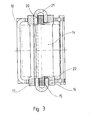
- the belt retractor has a C-shaped housing 10 with two side plates 11, which are held at a predetermined distance by a spacer rod 12 arranged on the open housing side.
- a belt winding shaft 14 is rotatably mounted, on which belt webbing, not shown in detail, is wound.
- the belt winding shaft 14 consists of a flat rectangular steel sheet 15 as the core and two half-shells 16, 17 of a shaft plastic body. At the end projecting beyond the one side plate, the shaft 14 is coupled to a winding spring 18 (FIG. 7), which on the other hand is attached to a plastic cover 19.
- a connecting rod 20 is arranged at the two ends of the steel core 15, which are clipped with their round section running along the steel core 15 in a form-fitting manner so that they can rotate in the half-shell profile.
- the connecting rods 20 are bent in a U-shaped manner, with the bent portions 21 thus constituting the bent elements symmetrically encompassing the steel core 15 and on the side or half-shell 16, 17 opposite the associated connecting rod 20 in a recess 22 formed there accordingly Wave profile are fitted.
- a circumferential toothing 23 is formed with tooth flanks 21 which are rounded in accordance with the round profile of the crooks 21 arranged for engagement in the toothing 23.
- FIGS. 4-6 show the so-called system side of the belt retractor, on which the belt-sensitive or vehicle-sensitive control system is provided for deflecting the bent portions 21 of the connecting rod 20 acting as locking members in their blocking position;
- Such systems are known in structure and mode of operation, for example from DE-GM 74 25 531.
- a tooth gap control device is provided, as described in detail in DE-OS 28 17 214 according to the task and mode of operation, since in particular With regard to a synchronous locking of the belt retractor at four points, the avoidance of tooth-on-tooth blocking is of particular importance.
- the shaft 14 continues via the side plate 11 with a bearing journal 24 which is fitted with a flange 25 between the half-shells 16, 17 of the shaft body 14 and is enclosed and held by them in the assembled state.
- the shaft 14 is mounted with the journal 24 in a housing cover 26 which is attached to the side plate 11.
- a control disk 27 and an inertial mass 28 are rotatably mounted on the bearing journal 24 with the shaft 14, which are loaded against one another by a spring 29 acting as a g-value spring.
- a control lever 30 is arranged on the control disk 27, which, when the inertial mass 28 and the control disk 27 are mutually rotated, is driven by the former into a circumferential internal toothing 31 of the housing cover 26 and thus holds the control disk 27 in its further rotation in a respectively defined position.
- the inertial mass is designed in a symmetrical, pendulum-like manner with two T-shaped cutouts over the ends of the shaft core 15 (FIG. 4).
- the control disk 27 has an external toothing 27a which interacts with a vehicle-sensitive system, not shown, in the sense of stopping the rotary movement of the control disk 27.
- the connecting rods 20 with the U-shaped bent portions 21 pass through the control disk twice, so that the control disk 27 is mounted directly next to the end of the shaft 14.
- the actuating through opening 32 is formed with radial play to control the radially pivotable crank 21 from the wave profile 16, 17 into the blocking position with engagement in the housing teeth 23, so that a relative movement of the control disc 27 opposite the wave profile 14 causes a radial pivoting of the bent portion 21 by the control gap 32 causing the radial deflection.
- FIGS. 7 and 8 show the side of the belt retractor with the winding spring 18 opposite the system side described.
- a reset disk 33 for the locking members 21 is additionally arranged, from the point of view of symmetry in the same way as the control disk 27.
- the reset disk 33 is penetrated symmetrically twice in openings 34 by the connecting rods 20 with offsets 21, so that also the reset disk 33 is arranged and mounted directly next to the shaft end.
- each opening 34 of the reset disk 33 merges into a bevel 35 which is directed radially outward in accordance with the blocking position of the locking members 21, the transitions being rounded such that the bent portions 21 are easily guided in openings 34 and associated bevels 35 results.
- the return disk 33 is coupled via a spring 36 to the shaft 14, which is supported by a pin 37 arranged on the associated half-shell 16, 17.
- the self-locking belt reel-up shown in this way works as follows: In normal operation, the belt webbing can be pulled off or wound on the shaft 14, the components coupled in their rotational movement to the shaft 14, namely the return disk 33 on the one hand and the control disk 27 and inertial mass 28 on the other turn with shaft 14. If there is a corresponding shaft acceleration due to a belt acceleration above the response threshold of the g-value spring 29, the result is a relative rotation of the control disk 27 and the inertial mass 28 relative to one another, the inertial mass 28 for deflecting the lever 30 into the toothing 31 the housing cover provides, whereby the engagement of the lever 30 in said toothing then prevents further rotation of the control disc 27 at a defined location. A corresponding stop of the rotary movement of the control disk 27 is brought about when the vehicle-sensitive system (not shown) responds by an engagement of a sensor-controlled lever in the external toothing 27a of the control disk 2.
- the housing for the belt retractor can be kept very small, since one-sided loads, twisting of the shaft and a punctiform load on the shaft bearing due to radial stress on the shaft itself no longer occur.
- the same pairs of forces form at the opposite blocking points, which brings about a symmetrical load.
- FIGS. 9 and 9a The simple manufacture of the wire pawls as connecting rods 20 with bent locking member designs 21 is finally shown in FIGS. 9 and 9a, in which the two-part shaft design is also clearly expressed.
- FIGS. 10 and 10a further savings in the width of the belt retractor can be achieved by flattening the bends of the bent portions 21 relative to the connecting rods 20.
Landscapes
- Engineering & Computer Science (AREA)
- Mechanical Engineering (AREA)
- Automotive Seat Belt Assembly (AREA)
Claims (14)
Applications Claiming Priority (2)
| Application Number | Priority Date | Filing Date | Title |
|---|---|---|---|
| DE3614283 | 1986-04-26 | ||
| DE19863614283 DE3614283A1 (de) | 1986-04-26 | 1986-04-26 | Gurtaufroller |
Publications (2)
| Publication Number | Publication Date |
|---|---|
| EP0243883A1 EP0243883A1 (fr) | 1987-11-04 |
| EP0243883B1 true EP0243883B1 (fr) | 1990-08-29 |
Family
ID=6299667
Family Applications (1)
| Application Number | Title | Priority Date | Filing Date |
|---|---|---|---|
| EP87105968A Expired - Lifetime EP0243883B1 (fr) | 1986-04-26 | 1987-04-23 | Enrouleur pour sangle |
Country Status (4)
| Country | Link |
|---|---|
| US (1) | US4802634A (fr) |
| EP (1) | EP0243883B1 (fr) |
| DE (2) | DE3614283A1 (fr) |
| ZA (1) | ZA872916B (fr) |
Families Citing this family (12)
| Publication number | Priority date | Publication date | Assignee | Title |
|---|---|---|---|---|
| KR100225766B1 (ko) * | 1991-04-11 | 1999-10-15 | 타카다 쥬우이찌로오 | 시이트벨트 리트랙터 |
| JPH04314650A (ja) * | 1991-04-11 | 1992-11-05 | Takata Kk | シートベルトリトラクタ |
| JP3093852B2 (ja) * | 1992-01-30 | 2000-10-03 | タカタ株式会社 | シートベルトリトラクタ |
| JP3233429B2 (ja) * | 1992-03-06 | 2001-11-26 | タカタ株式会社 | シートベルトリトラクタ |
| KR100249998B1 (ko) * | 1992-03-24 | 2000-05-01 | 다카다 쥬이치로 | 시이트벨트 리트랙터 |
| JPH05278566A (ja) * | 1992-04-06 | 1993-10-26 | Takata Kk | シートベルトリトラクタ |
| JPH08133011A (ja) * | 1994-11-07 | 1996-05-28 | Tokai Rika Co Ltd | ウエビング巻取装置 |
| DE19757373A1 (de) * | 1997-12-22 | 1999-06-24 | Takata Europ Gmbh | Anordnung zum Aufrollen eines Gurtbandes |
| DE19901143C1 (de) * | 1999-01-14 | 2000-05-04 | Norma Tallinn As | Sicherheitsgurt-Aufroller |
| EP1619091B1 (fr) | 2004-07-20 | 2007-10-03 | Key Safety Systems, Inc. | Rétracteur |
| GB201121604D0 (en) | 2011-12-15 | 2012-01-25 | Airbus Uk Ltd | A shaft locking device |
| CN103010990B (zh) * | 2012-12-03 | 2015-04-15 | 浙江双友物流器械股份有限公司 | 一种绞车的带轴连接件及制作方法 |
Family Cites Families (9)
| Publication number | Priority date | Publication date | Assignee | Title |
|---|---|---|---|---|
| GB1022344A (en) * | 1962-07-09 | 1966-03-09 | Britax London Ltd | Improvements in and relating to safety belts |
| US3471100A (en) * | 1966-05-17 | 1969-10-07 | Robert N Arcari | Self-adjusting safety reel |
| CH487009A (de) * | 1968-03-01 | 1970-03-15 | R Weber Georges | Rétracteur à verrouillage d'urgence pour ceinture de sécurité |
| SE404131B (sv) * | 1975-12-09 | 1978-09-25 | Graenges Essem Ab | Lasanordning vid for fordon avsedda sekerhetsselar |
| DE2817214A1 (de) * | 1978-04-20 | 1979-10-31 | Autoflug Gmbh | Gurtaufroller mit automatischer blockierung fuer kraftfahrzeug-sicherheitsgurte |
| DE2826286C2 (de) * | 1978-06-15 | 1989-07-20 | Repa Feinstanzwerk Gmbh, 7071 Alfdorf | Sicherheitsgurtaufrollautomat |
| DE3303209A1 (de) * | 1983-02-01 | 1984-08-02 | Hans-Hellmut Dipl.-Ing. 2061 Sülfeld Ernst | Blockiereinrichtung fuer sicherheitsgurtaufrollautomaten |
| DE3339527A1 (de) * | 1983-11-02 | 1985-05-09 | Autoflug Gmbh, 2084 Rellingen | Aufwickelvorrichtung fuer sicherheitsgurte |
| DE3341289A1 (de) * | 1983-11-15 | 1985-05-30 | Autoflug Gmbh, 2084 Rellingen | Doppelseitig sperrbarer gurtaufroller |
-
1986
- 1986-04-26 DE DE19863614283 patent/DE3614283A1/de not_active Withdrawn
-
1987
- 1987-04-23 EP EP87105968A patent/EP0243883B1/fr not_active Expired - Lifetime
- 1987-04-23 DE DE8787105968T patent/DE3764527D1/de not_active Expired - Fee Related
- 1987-04-24 US US07/042,414 patent/US4802634A/en not_active Expired - Fee Related
- 1987-04-24 ZA ZA872916A patent/ZA872916B/xx unknown
Also Published As
| Publication number | Publication date |
|---|---|
| DE3614283A1 (de) | 1987-10-29 |
| ZA872916B (en) | 1987-12-30 |
| EP0243883A1 (fr) | 1987-11-04 |
| DE3764527D1 (de) | 1990-10-04 |
| US4802634A (en) | 1989-02-07 |
Similar Documents
| Publication | Publication Date | Title |
|---|---|---|
| EP0243883B1 (fr) | Enrouleur pour sangle | |
| DE2826286C2 (de) | Sicherheitsgurtaufrollautomat | |
| DE2606293C3 (de) | Vorrichtung zum Zurückziehen und Aufrollen eines Sicherheitsgurtes | |
| DE3711537C2 (fr) | ||
| WO1997033778A1 (fr) | Systeme combine pour enrouler et tendre une ceinture, muni d'un limiteur de force | |
| EP0067322B1 (fr) | Dispositif pour l'enroulement d'une sangle de ceinture de sécurité | |
| DE3937149A1 (de) | Kreuzspulmess- und -anzeigegeraet | |
| DE10061086B4 (de) | Sitzgurteinzieheinrichtung | |
| DE3011283A1 (de) | Sicherheitsgurtaufroller | |
| DE3049564C2 (fr) | ||
| EP0472529B1 (fr) | Enrouleur de ceinture de securite avec dispositif de deblocage | |
| DE3744274A1 (de) | Elektromotor, insbesondere elektrischer kleinmotor | |
| EP0963889B1 (fr) | Bobine d'enroulement pour un rétracteur de sangle d'un système de retenue d'un occupant de véhicule | |
| EP2797779A2 (fr) | Enrouleur autobloquant doté d'un dispositif permettant la déconnexion de son système de commande sensible à la sangle en agissant sur l'arbre d'entraînement | |
| DE2915750A1 (de) | Selbstsperrender gurtaufroller fuer sicherheitsgurte | |
| EP0335360B1 (fr) | Enrouleur de ceinture | |
| DE10337252B4 (de) | Gurtspule für einen Gurtaufroller | |
| DE3116705C2 (fr) | ||
| DE2817214A1 (de) | Gurtaufroller mit automatischer blockierung fuer kraftfahrzeug-sicherheitsgurte | |
| DE2823334A1 (de) | Selbstsperrender gurtaufroller fuer sicherheitsgurte | |
| DE3341289A1 (de) | Doppelseitig sperrbarer gurtaufroller | |
| DE2122419C2 (de) | Aufwickelvorrichtung für einen Sicherheitsgurt | |
| DE3539280A1 (de) | Gurtaufroller mit klemmvorrichtung | |
| WO2018087266A1 (fr) | Rétracteur de ceinture | |
| DE1781365B1 (de) | Gurtaufroller |
Legal Events
| Date | Code | Title | Description |
|---|---|---|---|
| PUAI | Public reference made under article 153(3) epc to a published international application that has entered the european phase |
Free format text: ORIGINAL CODE: 0009012 |
|
| AK | Designated contracting states |
Kind code of ref document: A1 Designated state(s): DE ES FR GB IT SE |
|
| 17P | Request for examination filed |
Effective date: 19880503 |
|
| 17Q | First examination report despatched |
Effective date: 19890620 |
|
| GRAA | (expected) grant |
Free format text: ORIGINAL CODE: 0009210 |
|
| AK | Designated contracting states |
Kind code of ref document: B1 Designated state(s): DE ES FR GB IT SE |
|
| PG25 | Lapsed in a contracting state [announced via postgrant information from national office to epo] |
Ref country code: SE Free format text: THE PATENT HAS BEEN ANNULLED BY A DECISION OF A NATIONAL AUTHORITY Effective date: 19900829 |
|
| REF | Corresponds to: |
Ref document number: 3764527 Country of ref document: DE Date of ref document: 19901004 |
|
| ITF | It: translation for a ep patent filed |
Owner name: BARZANO' E ZANARDO MILANO S.P.A. |
|
| ET | Fr: translation filed | ||
| PG25 | Lapsed in a contracting state [announced via postgrant information from national office to epo] |
Ref country code: ES Free format text: LAPSE BECAUSE OF FAILURE TO SUBMIT A TRANSLATION OF THE DESCRIPTION OR TO PAY THE FEE WITHIN THE PRESCRIBED TIME-LIMIT Effective date: 19901210 |
|
| GBT | Gb: translation of ep patent filed (gb section 77(6)(a)/1977) | ||
| RAP2 | Party data changed (patent owner data changed or rights of a patent transferred) |
Owner name: AUTOFLUG GMBH & CO FAHRZEUGTECHNIK |
|
| PG25 | Lapsed in a contracting state [announced via postgrant information from national office to epo] |
Ref country code: GB Effective date: 19910423 |
|
| ITTA | It: last paid annual fee | ||
| PLBE | No opposition filed within time limit |
Free format text: ORIGINAL CODE: 0009261 |
|
| STAA | Information on the status of an ep patent application or granted ep patent |
Free format text: STATUS: NO OPPOSITION FILED WITHIN TIME LIMIT |
|
| 26N | No opposition filed | ||
| GBPC | Gb: european patent ceased through non-payment of renewal fee | ||
| PG25 | Lapsed in a contracting state [announced via postgrant information from national office to epo] |
Ref country code: FR Effective date: 19911230 |
|
| REG | Reference to a national code |
Ref country code: FR Ref legal event code: ST |
|
| PGFP | Annual fee paid to national office [announced via postgrant information from national office to epo] |
Ref country code: DE Payment date: 19950406 Year of fee payment: 9 |
|
| PG25 | Lapsed in a contracting state [announced via postgrant information from national office to epo] |
Ref country code: DE Effective date: 19970101 |
|
| PG25 | Lapsed in a contracting state [announced via postgrant information from national office to epo] |
Ref country code: IT Free format text: LAPSE BECAUSE OF NON-PAYMENT OF DUE FEES;WARNING: LAPSES OF ITALIAN PATENTS WITH EFFECTIVE DATE BEFORE 2007 MAY HAVE OCCURRED AT ANY TIME BEFORE 2007. THE CORRECT EFFECTIVE DATE MAY BE DIFFERENT FROM THE ONE RECORDED. Effective date: 20050423 |