EP0335360B1 - Enrouleur de ceinture - Google Patents
Enrouleur de ceinture Download PDFInfo
- Publication number
- EP0335360B1 EP0335360B1 EP89105510A EP89105510A EP0335360B1 EP 0335360 B1 EP0335360 B1 EP 0335360B1 EP 89105510 A EP89105510 A EP 89105510A EP 89105510 A EP89105510 A EP 89105510A EP 0335360 B1 EP0335360 B1 EP 0335360B1
- Authority
- EP
- European Patent Office
- Prior art keywords
- belt
- locking
- belt retractor
- retractor according
- coiling shaft
- Prior art date
- Legal status (The legal status is an assumption and is not a legal conclusion. Google has not performed a legal analysis and makes no representation as to the accuracy of the status listed.)
- Expired - Lifetime
Links
Images


Classifications
-
- B—PERFORMING OPERATIONS; TRANSPORTING
- B60—VEHICLES IN GENERAL
- B60R—VEHICLES, VEHICLE FITTINGS, OR VEHICLE PARTS, NOT OTHERWISE PROVIDED FOR
- B60R22/00—Safety belts or body harnesses in vehicles
- B60R22/34—Belt retractors, e.g. reels
- B60R22/36—Belt retractors, e.g. reels self-locking in an emergency
- B60R22/405—Belt retractors, e.g. reels self-locking in an emergency responsive to belt movement and vehicle movement
Definitions
- the invention relates to a belt retractor for a motor vehicle seat belt restraint system with a vehicle-sensitive and belt-band-sensitive locking mechanism, which has a locking toothing fixed to the housing and an opposing pawl on a side surface of the belt winding shaft, which is pivotally mounted to this and which is disengaged by a return spring in its rest position is pretensioned with the locking toothing and can be pivoted in a vehicle-sensitive manner in locking engagement with the locking toothing by means of a control cam on a control disk which can be rotated relative to the belt winding shaft and which is provided on its outer circumference with control teeth which interact with a control pawl which can be controlled by a vehicle-sensitive sensor.
- Belt retractors of this type are known in numerous designs.
- FR-A-2 413 914 which forms a rule, discloses such an embodiment.
- the development of belt retractors has led from simple locking mechanisms, which directly control the pawl by means of a pendulum or the like, to complex, so-called indirect locking, both vehicle-sensitive and belt-strap-sensitive locking mechanisms. These meet the strict requirements for a low response threshold and safe function by avoiding tooth bouncing when the tooth tips of the pawl and ratchet teeth meet.
- a control disk is provided which, via a control cam, presses the pawl into locking engagement with the locking teeth when it is rotated relative to the belt spool.
- This relative rotation occurs in a vehicle-sensitive manner in that the control disk is stopped in its rotational movement by a control pawl which is driven into the path of the control teeth on the outer circumference of the control disk by an inertia sensor.
- Belt-sensitive this relative rotation is caused by the fact that the control disk is also designed as an inertial disk or is permanently assigned to an inertial disk, so that it remains behind the latter when the belt winding shaft is suddenly accelerated.
- the object of the present invention is to improve them further in two respects: on the one hand, the so-called blocking path, which is the rotation angle of the belt winding shaft from the beginning of the Triggering the locking process until the locking effect occurs, be reduced, and on the other hand, this functional improvement should be paired with a simplified construction that lowers the manufacturing costs.
- the pawl is mounted in its center of gravity and the webbing-sensitive locking takes place solely under the action of inertia forces.
- the invention is based on the idea that there is no need for the participation of a control disk for the webbing-sensitive locking.
- the locking path defined above is determined, among other things, by the angle of rotation of the control disk relative to the belt winding shaft, which is required to carry out the complete control stroke of the control cam.
- a significantly shorter locking path can be achieved by the inventive design of the belt retractor with belt-sensitive locking, because the pawl strives for sudden acceleration of the belt winding shaft to remain in its position and is consequently pivoted by the rotation of the belt winding shaft immediately into locking engagement with the locking teeth.
- Another advantage is a simplification and weight saving on the control disc, which now does not have to be provided with a mass body such as an inertia disc or the like for the webbing-sensitive control. This advantage is particularly significant if the belt retractor is equipped with a back tensioning device which, during a back tensioning operation, exposes a control disk combined with an inertia disk to extremely high loads.
- a second pawl is pivotally mounted eccentrically at the axial end of the belt winding shaft and is offset in the circumferential direction relative to the first pawl by an angle that is a fraction the dividing step corresponds to the locking teeth fixed to the housing. So if the one pawl with its tooth tip meets a tooth tip of the locking toothing, the tooth tip of the other pawl certainly hits a tooth gap. A possible bouncing tooth has therefore no harmful effect.
- the two pawls are of identical design, preferably in a plan view in the form of a parallelogram, the sharp corner of which forms the tip of a pawl, and if the two pawls are arranged approximately diametrically opposite one another.
- the available space is optimally used, since pawls that can withstand high mechanical stress can be accommodated in an approximately cylindrical volume, the height of which corresponds to the width of a ring that supports the locking toothing.
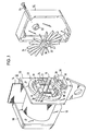
- a belt retractor is shown in perspective with the housing cap removed and opened from the side of the locking mechanism.
- the belt retractor generally designated 10, has a housing 12 in the form of a U-shaped frame, in the side plates of which a belt winding shaft 18 is rotatably mounted, on which the belt webbing 14 is wound.
- the belt winding shaft has a shaft extension 16 which protrudes from a side surface of the belt winding shaft 18 and from the housing 12.
- a ring part 22 is fastened, which is provided with an internal toothing which forms a locking toothing 24 fixed to the housing.
- an open bearing housing 26 for a control pawl 28 pivotably mounted therein is fastened to the side plate 20 of the housing 12.
- the control pawl 28 rests on a metal ball 30, which is held in the bearing housing 26 and forms an inertia sensor.
- a control disk 32 is rotatably mounted on the shaft extension 16.
- This control disk 32 consists of a bearing hub, from which control teeth 34 protrude in a star shape, and a control cam 36 integrally formed on the bearing hub.
- the housing cap 50 shown removed in FIG. 1 is provided on its inside with a bearing bush 52 in which the end of the shaft extension 16 is mounted easily is.
- the housing cap 50 is fastened to the side plate 20 of the housing 12 by means of screws 54.
- an assembly 56 is fastened in a similar manner, which accommodates a winding spring of the belt retractor in the usual way.
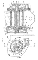
- the longitudinal section shown in Fig. 6 shows that the locking mechanism of the belt retractor is symmetrical.
- a corresponding locking toothing and two locking pawls 38A, 40A are provided on the other side.
- the pawls 38 and 38A are rigidly connected to each other by a shaft 60 which is rotatably mounted in an axial bore 62 of the belt winding shaft 18.
- the pawls 38, 38A are positively placed on the ends of the shaft 60 and fastened thereon, for example, by caulking.
- the two pawls 40, 40A are connected to one another in a similar manner by a shaft.
- the locking teeth 24, 24A and the pawls 38 and 38A and 40 and 40A are each aligned.
- Each of the pawls 38, 38A and 40, 40A is supported in its center of gravity.
- Each of these pawls has a parallelogram shape in plan view and each has a ratchet tooth Z formed by an acute corner of the parallelogram shape.
- a pressure spring 70 or 72 is supported on each locking pawl 38, 40 with one end, the other end of which is supported on an abutment 74 or 76 fastened in the side of the belt winding shaft 18, which at the same time serves as a stop for the adjacent pawl 40 or 38.
- the compression springs 70, 72 hold the pawls 38, 40 elastically in their rest position defined by the abutments 74, 76 out of engagement with the locking teeth 24.
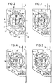
- Fig. 2 shows the pawls 38, 40 in the idle state.
- the opposite, corresponding pawls 38A, 40A are in the analog rest position.
- the pawls 38, 40 are only approximately diametrically opposed to each other.
- two diamond lines D1 and D2 are shown, of which the line D1 runs through the axis of the shaft extension 16 and through the axis of the journal 42, while the line D2 runs through the axis of the shaft extension 16 and the axis of the journal 44.
- the two diamond lines D1 and D2 are rotated relative to one another by an angle which corresponds to a fraction of the tooth pitch of the locking teeth 24.
- the tooth tips Z of the pawls 38, 40 (and 38A, 40A) are thus offset from one another in the circumferential direction of the belt winding shaft 18 by an angle which corresponds to a fraction of the division step of the locking toothing 24.
- FIG. 3 shows the vehicle-sensitive locking by turning the pawl 40 into locking engagement with the locking toothing 24.
- the control cam 36 of the control disk 32 which is only indicated in FIGS. 2 to 5, is rotated with the control disk with respect to the belt winding shaft 18 by a few degrees , since the control disc 32 is stopped in its rotational movement by the control pawl 28 raised above the ball 30, which engages in front of a control tooth 34. Due to the relative rotation between the belt winding shaft 18 and the control disk 32, the control cam 36 moves away from the stop defining its rest position and presses the pawl 40 radially outward, so that it is pivoted and is driven with its ratchet tooth Z into a tooth gap of the ratchet teeth 24. The pawl 38 remains in its rest position.
- the tooth tip Z of the pawl 40 precisely meets a tip of the locking toothing 24.
- any bouncing off of the pawl 40 cannot call into question the immediate production of the locking effect, since the locking pawl 38 with its tooth tip Z into a tooth gap between two adjacent teeth of the locking toothing 24 and with subsequent relative rotation between the belt winding shaft 18 and locking toothing 24 the locking pawl 38 engages in locking engagement with the locking toothing 24 by only a few degrees.
- the pawls 38, 40 and 38A, 40A are movable independently of one another. According to a further development, not shown in the drawing, the movements of the pawls are synchronized with one another by suitable connecting means.
- the degree of displacement of the two pawls 38, 40 and 38A, 40A in the circumferential direction against each other is determined in dependence on the tooth geometry so that, on the one hand, the other pawl with its tooth tip also coincides with the eventual encounter of two tooth tips Safety does not also hit a tooth tip, on the other hand when a pawl bounces off, but the angle of rotation until the other pawl engages in a tooth gap is as small as possible.
- the blocking load is then absorbed by both pawls, since a certain plastic deformation of the functional parts of the locking mechanism occurs.
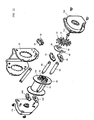
- two pairs of pawls 38, 38A and 40, 40A are again provided. These pawls are each mounted in their center of gravity and have a circular outer circumference, which is inscribed in the circular outer contour 80 of the belt winding shaft 18. Each pawl 38, 38A, 40, 40A is arranged in a free space which is formed between two axial extensions 82, 84 of the belt winding shaft 18 which are approximately segment-shaped in plan view. The outer circumference of the axial extensions 82, 84 is also inscribed in the circular outer contour 80 of the belt winding shaft 18. The axial extensions 82, 84 are dimensioned such that they project in the axial direction outward beyond the locking teeth 24 fixed to the housing. Fig.
- FIG. 7 shows the pawls 38, 40 in their rest position, in which they are acted upon by a leaf spring 85 or 88 bent from a spring plate part 85, which is anchored to the adjacent axial extension 82 or 84.
- 8 shows the pawls 38, 40 in their activated state, deflected in the direction of the locking teeth 24.
- the rest position of the pawls 38, 40 is determined by further axial lugs 90, 92 of the belt winding shaft 18, on which the adjacent pawl 40 and 38 is held elastically in contact.
- the control disk 32 carries on a hub two control diamonds 94, 96 arranged approximately diametrically opposite one another, of which the first actuates the pawl 40 and the second actuates the pawl 38 in a vehicle-sensitive manner when the control pawl 28 engages in the control teeth 34 of the control disk 32.
- the pawls 38, 38A and 40, 40A are each rigidly connected to one another in pairs by a shaft 60 which is mounted in a bearing bore 62 of the belt winding shaft 18. In the axial ends of each bearing bore 62, a bearing bush 100 made of resilient material is inserted.
- the resilience of the mounting of each shaft 60 is designed such that, under blocking load, both pairs of pawls engage in a tooth gap of the pawl teeth 24 fixed to the housing, although the contact surfaces Z of the pawls 38, 38A compared to the contact surfaces Z of the pawls 40, 40A with respect to the division of the pawl teeth 24 are offset from one another in the circumferential direction by approximately a fraction of the dividing step.
- a blocking process initially only two pawls 38, 38A or 40, 40A are inserted into the locking toothing 24 in a locking manner, however, with the subsequent increase in the blocking load, the bearing bushes 100 are deformed in the circumferential direction, so that the respective other pair of pawls also block the blocking load into the housing Locking teeth 24 initiates (Fig. 8).
- Another special feature of this embodiment is that under high blocking loads the pawls are supported with their back surface facing away from the respective contact surface on the adjacent shoulder 82A or 84A of the axial extension 82 or 84.
- FIGS. 9 and 10 Another special feature of the described embodiment can be seen from FIGS. 9 and 10. It relates to the mounting of the belt winding shaft 18.
- the belt winding shaft 18 On the side of the control disk 32, the belt winding shaft 18 is provided at its axial end with a bearing pin 102 which can be rotated easily in a bearing bush 106 is formed in a housing cover 104.
- the bearing bush 106 is surrounded by a double concentric bead 108, which is also molded into the housing cover 104 and by means of which the bearing bush 106 is resiliently held in the radial direction.
- the belt winding shaft 18 is supported by means of a bearing extension 110 in a bearing bush 112, which is held by a housing cover 116 which surrounds the winding spring 114 and which is radially and elastically fastened to the adjacent side wall of the housing 20.
- the housing cover 116 has on its side facing the housing 20 molded, elastically deflectable pins 120, each of which is inserted with its free end into an associated bore in the side wall of the housing 20.
- the housing cover 116 is provided on its outer circumference with a flange-like extension 116A, in which radially directed elongated holes are provided, through which collar pins 122 anchored in the side plate of the housing 20 engage, so that it can be moved radially around the housing cover 116 on the side wall of the housing 20 to fix.
- the belt winding shaft 18 is thus equipped with a smooth-running fine bearing which yields elastically under load, so that the belt winding shaft 18 with its axial extensions 82, 84 and with the pawls 38, 38A and 40, 40A is supported on the housing-fixed locking teeth 24, which then acts as a rough storage.
- This state, in which both pairs of pawls introduce the blocking load into the locking toothing 24 and the belt winding shaft 18 is supported with its outer circumference on the locking toothing 24 fixed to the housing is illustrated in FIG. 8.
- the various components of the seat belt retractor are assembled in a housing 20 with a retracted base plate and angled side walls, which enable the belt winding shaft to be inserted radially with components preassembled thereon and then be erected by straightening the base plate of the housing and placed in parallel.
Claims (18)
- Enrouleur de ceinture (10) pour un système de retenue d'une ceinture de securité d'un véhicule automobile, comportant un mécanisme de blocage sensible au véhicule et sensible à la ceinture, qui présente une denture de blocage (24) solidaire du boîtier et au moins deux cliquets d'arrêt (38, 40) opposés à celle-ci, montés pivotants, sur une face latérale (20) de l'arbre (18) d'enroulement de la ceinture, de manière excentrique par rapport à celui-ci, lesquels cliquets sont précontraints élastiquement dans leur position de repos, lorsqu'ils ne sont pas en prise avec la denture de blocage (24), et pivotants de manière sensible au véhicule, lorsqu'ils sont en prise avec la denture de blocage (24), grâce à une came de commande (36) chacun d'un disque de commande (32) tournant par rapport à l'arbre (18) d'enroulement de la ceinture, ce disque étant pourvu sur son pourtour extérieur de dents de commande (34) qui coopèrent avec un cliquet de commande (28) commandé par un capteur sensible au véhicule, caractérisé en ce que les cliquets d'arrêt (38, 40, 38A, 40A) sont suspendus chacun au moins à peu près en leur centre de gravité, et le blocage sensible à la ceinture s'effectue uniquement sous l'effet de forces d'inertie, en ce que les surfaces d'attaque (Z) des cliquets d'arrêt (38, 38A, 40, 40A), sur le côté de l'arbre (18) d'enroulement de la ceinture, sont décalées l'une par rapport à l'autre dans la direction périphérique, d'un angle qui correspond à une fraction du pas de division de la denture de blocage (24) solidaire du boîtier.
- Enrouleur de ceinture selon la revendication 1, caractérisé en ce que le cliquet d'arrêt (38, 40, 38A, 40A) présente, en vue de dessus, la forme d'un parallélogramme dont un angle aigu forme la pointe (Z) d'une dent de blocage.
- Enrouleur de ceinture selon la revendication 1, caractérisé en ce que les cliquets d'arrêt (38, 38A, 40, 40A) sont disposés à peu près diamétralement opposés les uns aux autres.
- Enrouleur selon l'une des revendications 1 à 3, caractérisé en ce que les cliquets d'arrêt (38, 38A, 40, 40A) sont de configuration identique.
- Enrouleur de ceinture selon l'une des revendications 1 à 4, caractérisé en ce que chaque cliquet d'arrêt (38, 38A, 40, 40A) est précontraint, dans sa position de repos, par un ressort de pression (70, 72) qui prend appui par l'une de ses extrémités contre le cliquet d'arrêt (38, 40) correspondant, et par son autre extrémité contre une butée (74, 76) qui est fixée sur le côté de l'arbre (18) d'enroulement de la ceinture, et qui sert en même temps de butée pour le cliquet d'arrêt voisin (38, 40) afin de définir sa position de repos lorsqu'il n'est pas en prise avec la denture de blocage (24) solidaire du boîtier.
- Enrouleur de ceinture selon l'une des revendications 1 à 5, caractérisé en ce que les deux cliquets d'arrêt (38, 38A, 40, 40A) sont précontraints dans leur position de repos, par des ressorts de rappel (70, 72) de force différente.
- Enrouleur de ceinture selon l'une des revendications précédentes, caractérisé en ce que le mécanisme de blocage présente, de part et d'autre de l'arbre (18) d'enroulement de la ceinture, une denture de blocage (24, 24A) solidaire du boîtier, et deux cliquets d'arrêt (38, 38A, 40, 40A) coopérant avec celle-ci, et en ce que deux cliquets d'arrêt, alignés sur un côté et sur l'autre côté de l'arbre (18) d'enroulement de la ceinture, sont reliés entre eux de manière rigide par un arbre (60) qui est monté tournant dans un perçage (62) axial de l'arbre (18) d'enroulement de ceinture.
- Enrouleur de ceinture selon la revendication 7, caractérisé en ce que les arbres (60), reliant entre eux de manière rigide deux cliquets (38, 38A, 40, 40A), sont montés dans l'arbre (18) d'enroulement de ceinture, de manière suffisamment souple pour qu'au moins sous la charge de blocage, deux cliquets d'arrêt placés du même côté de l'arbre (18) d'enroulement de ceinture transmettent la charge de blocage à la denture de blocage (24) solidaire du boîtier, malgré leur décalage dans la direction périphérique, par rapport à la division de cette denture de blocage.
- Enrouleur de ceinture selon la revendication 8, caractérisé en ce que chaque arbre (60) est monté dans le perçage axial (62) de l'arbre (18) d'enroulement de ceinture, par au moins un fourreau (100) déformable élastiquement.
- Enrouleur de ceinture selon l'une des revendications précédentes, caractérisé en ce que chacun des cliquets d'arrêt (38, 38A, 40, 40A) et monté dans un espace libre sur le côté de l'arbre (18) d'enroulement de ceinture, qui est placé dans la direction périphérique, entre deux prolongements axiaux (82, 84) de l'arbre (18) d'enroulement de ceinture, lesquels se prolongent au moins jusqu'à la délimitation axiale et extérieure de la denture de blocage (24).
- Enrouleur de ceinture selon la revendication 10, caractérisé en ce que les prolongements axiaux (82, 84) sont inscrits dans le contour périphérique (80) de l'arbre (18) d'enroulement de ceinture.
- Enrouleur de ceinture selon les revendications 9, 10 et 11, caractérisé en ce que chaque cliquet d'arrêt (38, 38A, 40, 40A) présente sur sa face tournée à l'opposé de la surface d'attaque (Z), une surface arrière qui, sous la charge de blocage, vient s'appliquer contre un épaulement d'appui (82A, 84A) de forme adaptée, du prolongement axial (82, 84) adjacent de l'arbre (18) d'enroulement de ceinture, en raison de la suspension souple des arbres (60).
- Enrouleur de ceinture selon la revendication 12, caractérisé en ce que les cliquets d'arrêt (38, 38A, 40, 40A) sont inscrits dans leur position de repos, avec leur pourtour extérieur, dans le contour extérieur (80) circulaire de l'arbre (18) d'enroulement de ceinture.
- Enrouleur de ceinture selon l'une des revendications précédentes, caractérisé en ce que l'arbre (18) d'enroulement de ceinture est monté, à chacune de ses deux extrémités axiales, dans un palier fin (102, 106, 110, 112) cédant radialement lorsqu'il est sous charge.
- Enrouleur de ceinture selon la revendication 14, caractérisé en ce qu'il présente sur l'un des côtés axiaux de l'arbre d'enroulement de ceinture, un capteur sensible au véhicule et le couvercle de boîtier (104) entourant le disque de commande, ce boîtier étant pourvu d'un coussinet (106) maintenu de façon souple radialement, pour un tourillon (102) de l'arbre (18) d'enroulement de ceinture.
- Enrouleur de ceinture selon la revendication 15, caractérisé en ce que le coussinet (106) est maintenu dans une moulure (108), qui l'entoure concentriquement, du couvercle du boîtier (104).
- Enrouleur de ceinture selon l'une des revendications 14 à 16, caractérisé en ce qu'un ressort d'enroulement est placé dans un couvercle de boîtier (116) et en ce qu'un coussinet (112) pour l'extrémité axiale (110) adjacente de l'arbre (18) d'enroulement de ceinture est fixé sur le couvercle de boitier (116), et en ce que le couvercle de boîtier (116) est fixé de manière à coulisser radialement, sur la paroi latérale adjacente du boîtier d'enrouleur de ceinture (20).
- Enrouleur de ceinture selon la revendication 17, caractérisé en ce que le couvercle de boîtier (116) est pourvu de broches (120) venues de moulage, orientables élastiquement et dirigées axialement vers l'intérieur, lesquelles sont introduites, chacune à leur extrémité libre, dans un perçage associé de la paroi latérale du boîtier d'enrouleur de ceinture (20).
Priority Applications (1)
| Application Number | Priority Date | Filing Date | Title |
|---|---|---|---|
| AT89105510T ATE90045T1 (de) | 1988-03-29 | 1989-03-29 | Gurtaufroller. |
Applications Claiming Priority (4)
| Application Number | Priority Date | Filing Date | Title |
|---|---|---|---|
| DE3810656 | 1988-03-29 | ||
| DE3810656 | 1988-03-29 | ||
| DE3908666 | 1989-03-16 | ||
| DE3908666A DE3908666A1 (de) | 1988-03-29 | 1989-03-16 | Gurtaufroller |
Publications (3)
| Publication Number | Publication Date |
|---|---|
| EP0335360A2 EP0335360A2 (fr) | 1989-10-04 |
| EP0335360A3 EP0335360A3 (fr) | 1991-01-30 |
| EP0335360B1 true EP0335360B1 (fr) | 1993-06-02 |
Family
ID=25866503
Family Applications (1)
| Application Number | Title | Priority Date | Filing Date |
|---|---|---|---|
| EP89105510A Expired - Lifetime EP0335360B1 (fr) | 1988-03-29 | 1989-03-29 | Enrouleur de ceinture |
Country Status (3)
| Country | Link |
|---|---|
| EP (1) | EP0335360B1 (fr) |
| DE (2) | DE3908666A1 (fr) |
| ES (1) | ES2011226T3 (fr) |
Cited By (1)
| Publication number | Priority date | Publication date | Assignee | Title |
|---|---|---|---|---|
| DE102018116126A1 (de) * | 2018-07-04 | 2020-01-09 | Autoliv Development Ab | Gurtaufroller für eine Sicherheitsgurteinrichtung eines Kraftfahrzeuges |
Families Citing this family (6)
| Publication number | Priority date | Publication date | Assignee | Title |
|---|---|---|---|---|
| JPH08133011A (ja) * | 1994-11-07 | 1996-05-28 | Tokai Rika Co Ltd | ウエビング巻取装置 |
| DE29619380U1 (de) * | 1996-11-07 | 1997-03-06 | Trw Repa Gmbh | Kupplungsscheibe für einen Gurtaufroller |
| DE20215835U1 (de) | 2002-10-15 | 2003-02-27 | Trw Repa Gmbh | Gurtaufroller |
| DE102006048674B9 (de) * | 2006-10-14 | 2008-10-16 | Autoliv Development Ab | Sicherheitsgurtaufroller mit unverlierbar an der Gurtwelle gelagerter Sperrklinke |
| DE202007000909U1 (de) | 2007-01-18 | 2007-04-05 | Takata-Petri Ag | Sensoreinrichtung zur Aktivierung eines Sperrmechanismus für einen Gurtaufroller eines Kraftfahrzeugs |
| DE102016006636A1 (de) * | 2016-06-03 | 2017-12-07 | Trw Automotive Gmbh | Gurtaufroller für Kraftfahrzeuge |
Family Cites Families (3)
| Publication number | Priority date | Publication date | Assignee | Title |
|---|---|---|---|---|
| US3955774A (en) * | 1974-11-25 | 1976-05-11 | Sigmatex, A.G. | Belt winder for safety belts |
| IT7820419V0 (it) * | 1978-01-05 | 1978-01-05 | Piero Larocchi S N C Di Luigi | Dispositivo per il controllo automatico degli organi di bloccaggio e sbloccaggio delle cinture di sicurezza utilizzate sugli autoveicoli e simili. |
| DE3008299A1 (de) * | 1980-03-04 | 1981-09-10 | Repa Feinstanzwerk Gmbh, 7071 Alfdorf | Aufrollautomat fuer einen sicherheitsgurt |
-
1989
- 1989-03-16 DE DE3908666A patent/DE3908666A1/de not_active Withdrawn
- 1989-03-29 DE DE8989105510T patent/DE58904542D1/de not_active Expired - Fee Related
- 1989-03-29 EP EP89105510A patent/EP0335360B1/fr not_active Expired - Lifetime
- 1989-03-29 ES ES198989105510T patent/ES2011226T3/es not_active Expired - Lifetime
Cited By (2)
| Publication number | Priority date | Publication date | Assignee | Title |
|---|---|---|---|---|
| DE102018116126A1 (de) * | 2018-07-04 | 2020-01-09 | Autoliv Development Ab | Gurtaufroller für eine Sicherheitsgurteinrichtung eines Kraftfahrzeuges |
| DE102018116126B4 (de) | 2018-07-04 | 2021-10-14 | Autoliv Development Ab | Gurtaufroller für eine Sicherheitsgurteinrichtung eines Kraftfahrzeuges |
Also Published As
| Publication number | Publication date |
|---|---|
| ES2011226T3 (es) | 1993-12-01 |
| EP0335360A2 (fr) | 1989-10-04 |
| DE3908666A1 (de) | 1989-10-12 |
| ES2011226A4 (es) | 1990-01-01 |
| DE58904542D1 (de) | 1993-07-08 |
| EP0335360A3 (fr) | 1991-01-30 |
Similar Documents
| Publication | Publication Date | Title |
|---|---|---|
| DE2646238A1 (de) | Gurtaufroller fuer fahrzeug-sicherheitsgurte mit blockiervorrichtung | |
| DE2832160A1 (de) | Sicherheitsgurtaufroller | |
| WO1996022200A1 (fr) | Accouplement entre l'arbre d'un enrouleur de ceinture et un reducteur de rotation de tendeur de ceinture | |
| DE2639469A1 (de) | Gurtaufwickelvorrichtung | |
| DE2614603C2 (de) | Pendelsensor für die Sperrvorrichtung einer Sicherheitsgurteinziehvorrichtung | |
| EP1024981A1 (fr) | Accouplement pour tendeur de courroie avec entrainement en rotation | |
| DE102010046980A1 (de) | Selbstsperrender Gurtaufroller | |
| DE3418378A1 (de) | Gurtaufroller fuer fahrzeugsicherheitsgurte | |
| EP0335360B1 (fr) | Enrouleur de ceinture | |
| DE102014207297A1 (de) | Gurtaufroller für eine Sicherheitsgurteinrichtung | |
| DE3402422C2 (fr) | ||
| DE3049564C2 (fr) | ||
| EP0265926B1 (fr) | Dispositifs de capteur et de bloquage pour un système de ceintures de sécurité | |
| DE3810701A1 (de) | Rueckstrammvorrichtung | |
| DE2924575A1 (de) | Automatischer gurtblockierer fuer sicherheitsgurte | |
| DE10324195B4 (de) | Sicherheitsgurtaufroller mit einer drehwinkeldefinierten Abschaltung des gurtbandsensitiven Steuersystems | |
| EP0379956A2 (fr) | Rétracteur de ceinture de sécurité comportant un dispositif de serrage de sangle | |
| DE3627715A1 (de) | Sicherheitsgurtaufroller | |
| EP0646504B1 (fr) | Enrouleur de ceinture pour des systèmes de retenue dans des véhicules | |
| DE2852110A1 (de) | Aufroller fuer sicherheitsgurte in kraftfahrzeugen | |
| DE2326264C2 (de) | Gurtaufroller für einen Fahrzeugsicherheitsgurt | |
| DE2610870A1 (de) | Gurtaufroller fuer fahrzeug-sicherheitsgurte | |
| DE2832822C2 (de) | Sicherheitsgurtaufroller | |
| DE3403568A1 (de) | Selbstsperrender sicherheitsgurtaufroller | |
| DE19544918A1 (de) | Sicherheitsgurtaufroller |
Legal Events
| Date | Code | Title | Description |
|---|---|---|---|
| PUAI | Public reference made under article 153(3) epc to a published international application that has entered the european phase |
Free format text: ORIGINAL CODE: 0009012 |
|
| AK | Designated contracting states |
Kind code of ref document: A2 Designated state(s): AT BE DE ES FR GB IT NL SE |
|
| ITCL | It: translation for ep claims filed |
Representative=s name: DR. ING. A. RACHELI & C. |
|
| EL | Fr: translation of claims filed | ||
| GBC | Gb: translation of claims filed (gb section 78(7)/1977) | ||
| PUAL | Search report despatched |
Free format text: ORIGINAL CODE: 0009013 |
|
| AK | Designated contracting states |
Kind code of ref document: A3 Designated state(s): AT BE DE ES FR GB IT NL SE |
|
| RHK1 | Main classification (correction) |
Ipc: B60R 22/36 |
|
| 17P | Request for examination filed |
Effective date: 19910730 |
|
| 17Q | First examination report despatched |
Effective date: 19921023 |
|
| GRAA | (expected) grant |
Free format text: ORIGINAL CODE: 0009210 |
|
| AK | Designated contracting states |
Kind code of ref document: B1 Designated state(s): AT BE DE ES FR GB IT NL SE |
|
| PG25 | Lapsed in a contracting state [announced via postgrant information from national office to epo] |
Ref country code: NL Effective date: 19930602 Ref country code: BE Effective date: 19930602 |
|
| REF | Corresponds to: |
Ref document number: 90045 Country of ref document: AT Date of ref document: 19930615 Kind code of ref document: T |
|
| REF | Corresponds to: |
Ref document number: 58904542 Country of ref document: DE Date of ref document: 19930708 |
|
| ITF | It: translation for a ep patent filed |
Owner name: DR. ING. A. RACHELI & C |
|
| GBT | Gb: translation of ep patent filed (gb section 77(6)(a)/1977) |
Effective date: 19930810 |
|
| ET | Fr: translation filed | ||
| NLV1 | Nl: lapsed or annulled due to failure to fulfill the requirements of art. 29p and 29m of the patents act | ||
| REG | Reference to a national code |
Ref country code: ES Ref legal event code: FG2A Ref document number: 2011226 Country of ref document: ES Kind code of ref document: T3 |
|
| PG25 | Lapsed in a contracting state [announced via postgrant information from national office to epo] |
Ref country code: AT Effective date: 19940329 |
|
| PLBE | No opposition filed within time limit |
Free format text: ORIGINAL CODE: 0009261 |
|
| STAA | Information on the status of an ep patent application or granted ep patent |
Free format text: STATUS: NO OPPOSITION FILED WITHIN TIME LIMIT |
|
| 26N | No opposition filed | ||
| EAL | Se: european patent in force in sweden |
Ref document number: 89105510.5 |
|
| PGFP | Annual fee paid to national office [announced via postgrant information from national office to epo] |
Ref country code: SE Payment date: 19970128 Year of fee payment: 9 |
|
| PG25 | Lapsed in a contracting state [announced via postgrant information from national office to epo] |
Ref country code: SE Free format text: LAPSE BECAUSE OF NON-PAYMENT OF DUE FEES Effective date: 19980330 |
|
| EUG | Se: european patent has lapsed |
Ref document number: 89105510.5 |
|
| REG | Reference to a national code |
Ref country code: GB Ref legal event code: IF02 |
|
| PGFP | Annual fee paid to national office [announced via postgrant information from national office to epo] |
Ref country code: GB Payment date: 20030204 Year of fee payment: 15 |
|
| PGFP | Annual fee paid to national office [announced via postgrant information from national office to epo] |
Ref country code: FR Payment date: 20030303 Year of fee payment: 15 |
|
| PGFP | Annual fee paid to national office [announced via postgrant information from national office to epo] |
Ref country code: ES Payment date: 20030320 Year of fee payment: 15 |
|
| PG25 | Lapsed in a contracting state [announced via postgrant information from national office to epo] |
Ref country code: GB Free format text: LAPSE BECAUSE OF NON-PAYMENT OF DUE FEES Effective date: 20040329 |
|
| PG25 | Lapsed in a contracting state [announced via postgrant information from national office to epo] |
Ref country code: ES Free format text: LAPSE BECAUSE OF NON-PAYMENT OF DUE FEES Effective date: 20040330 |
|
| PGFP | Annual fee paid to national office [announced via postgrant information from national office to epo] |
Ref country code: DE Payment date: 20040331 Year of fee payment: 16 |
|
| GBPC | Gb: european patent ceased through non-payment of renewal fee |
Effective date: 20040329 |
|
| PG25 | Lapsed in a contracting state [announced via postgrant information from national office to epo] |
Ref country code: FR Free format text: LAPSE BECAUSE OF NON-PAYMENT OF DUE FEES Effective date: 20041130 |
|
| REG | Reference to a national code |
Ref country code: FR Ref legal event code: ST |
|
| PG25 | Lapsed in a contracting state [announced via postgrant information from national office to epo] |
Ref country code: IT Free format text: LAPSE BECAUSE OF NON-PAYMENT OF DUE FEES;WARNING: LAPSES OF ITALIAN PATENTS WITH EFFECTIVE DATE BEFORE 2007 MAY HAVE OCCURRED AT ANY TIME BEFORE 2007. THE CORRECT EFFECTIVE DATE MAY BE DIFFERENT FROM THE ONE RECORDED. Effective date: 20050329 |
|
| REG | Reference to a national code |
Ref country code: ES Ref legal event code: FD2A Effective date: 20040330 |
|
| PG25 | Lapsed in a contracting state [announced via postgrant information from national office to epo] |
Ref country code: DE Free format text: LAPSE BECAUSE OF NON-PAYMENT OF DUE FEES Effective date: 20051001 |