EP0243628B1 - Abdichtung von Apparaten bei kontinuierlicher Produktförderung - Google Patents
Abdichtung von Apparaten bei kontinuierlicher Produktförderung Download PDFInfo
- Publication number
- EP0243628B1 EP0243628B1 EP87103380A EP87103380A EP0243628B1 EP 0243628 B1 EP0243628 B1 EP 0243628B1 EP 87103380 A EP87103380 A EP 87103380A EP 87103380 A EP87103380 A EP 87103380A EP 0243628 B1 EP0243628 B1 EP 0243628B1
- Authority
- EP
- European Patent Office
- Prior art keywords
- section
- process according
- pressure
- agent
- passage
- Prior art date
- Legal status (The legal status is an assumption and is not a legal conclusion. Google has not performed a legal analysis and makes no representation as to the accuracy of the status listed.)
- Expired - Lifetime
Links
Images

Classifications
-
- F—MECHANICAL ENGINEERING; LIGHTING; HEATING; WEAPONS; BLASTING
- F16—ENGINEERING ELEMENTS AND UNITS; GENERAL MEASURES FOR PRODUCING AND MAINTAINING EFFECTIVE FUNCTIONING OF MACHINES OR INSTALLATIONS; THERMAL INSULATION IN GENERAL
- F16J—PISTONS; CYLINDERS; SEALINGS
- F16J15/00—Sealings
- F16J15/16—Sealings between relatively-moving surfaces
- F16J15/168—Sealings between relatively-moving surfaces which permits material to be continuously conveyed
-
- D—TEXTILES; PAPER
- D06—TREATMENT OF TEXTILES OR THE LIKE; LAUNDERING; FLEXIBLE MATERIALS NOT OTHERWISE PROVIDED FOR
- D06B—TREATING TEXTILE MATERIALS USING LIQUIDS, GASES OR VAPOURS
- D06B23/00—Component parts, details, or accessories of apparatus or machines, specially adapted for the treating of textile materials, not restricted to a particular kind of apparatus, provided for in groups D06B1/00 - D06B21/00
- D06B23/14—Containers, e.g. vats
- D06B23/18—Sealing arrangements
-
- Y—GENERAL TAGGING OF NEW TECHNOLOGICAL DEVELOPMENTS; GENERAL TAGGING OF CROSS-SECTIONAL TECHNOLOGIES SPANNING OVER SEVERAL SECTIONS OF THE IPC; TECHNICAL SUBJECTS COVERED BY FORMER USPC CROSS-REFERENCE ART COLLECTIONS [XRACs] AND DIGESTS
- Y10—TECHNICAL SUBJECTS COVERED BY FORMER USPC
- Y10S—TECHNICAL SUBJECTS COVERED BY FORMER USPC CROSS-REFERENCE ART COLLECTIONS [XRACs] AND DIGESTS
- Y10S57/00—Textiles: spinning, twisting, and twining
- Y10S57/908—Jet interlaced or intermingled
Definitions
- the invention relates to a method for sealing a passage for conveying preferably endless products - such as fibers or film strips - through a wall into a room which, due to a vapor or gaseous medium contained therein, has a pressure different from the external pressure in front of the wall and a Device for performing the method.
- process steps such as stretching, damping or relaxation are required, which are carried out at steam temperatures from 100 ° C to 150 ° C under a pressure of 1-2.5 bar in a closed chamber.
- these endless products are usually produced continuously, so that immediate further processing is advantageous in terms of economy and quality.
- losses occur due to the steam escaping into the environment, which are undesirable.
- Roll or labyrinth seals are known in which the product is inserted or exported into the chamber between more or less flexible barriers (see, for example, DE-B-2 633 981).
- the disadvantage of these devices is that in addition to an incomplete shut-off and high wear, product damage can occur.
- the object of the invention is to find a seal which, when a product, preferably a non-contact and continuously conveyed product, passes through a wall, prevents a flow of pressurized steam or gas from one side to the other, largely avoids wear and tear on the device, quickly Adaptability to different operating conditions allowed, excludes damage to the product and enables easy maintenance.
- the object is achieved in that a flow flowing in a passage almost parallel to the conveying path and in the direction of the higher pressure is introduced from a vapor or gaseous medium at a speed which is then reduced to such a distance by a partial reduction on the further spatially limited path Pressure is implemented, which corresponds approximately to the opposing pressure in the room and that at the point of entry of the agent in the spatially limited path, the pressure is set via the speed so that it approximately corresponds to the form in front of the wall.
- the method according to the invention it is possible to convey an endless product without contacting structural elements through a closed wall between two rooms at different pressures without, for example, the expensive media for treatment such as gases or steam escaping through this passage as a result of the pressure drop, which results in high costs or a strong pollution of the environment is avoided. Even by introducing small amounts of agent, the medium can be prevented from flowing away at the pressure differences of 0.1-5 bar, in particular 1-2.5 bar, which occur in production. If the contact between the flat strips and the passage walls is to be avoided, widths between 1.2 and 5 times, in particular between 1.5 and 3 times, the strip thickness have been found to be favorable, foil strips being generally smaller than fiber strips Need widths.
- Compression impacts in a convergent section with a slight incline (5 °) following the entry point mean that the pressure can be recovered in a short way, with low losses in relation to the diffuser with high friction losses, with the originally oblique compression impacts at the latest in the following straight section with a length of up to 20 mm, in particular up to 14 mm, in straight compression surges in order to be calmed down after falling below the sound limit in this section.
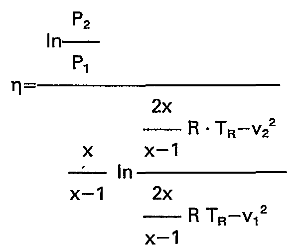
- the pressure recovery is designed so that the efficiency of the converging flow is between 0.4 to 0.8, preferably between 0, 7 to 0.8, whereby efficiency is to be understood:
- P 1 and P 2 mean the pressure or v 1 and V2 the speed at the beginning and end of the convergent section, while T R is the rest temperature in the channel.
- the flow is calmed in a diffuser while simultaneously adapting to the pressure in the chamber rectangular cross-sections an angle of 5-8 ° and in round cross-sections an angle of 610 ° no more adverse influence of the flow is exerted on the spinning belt.
- a cross section A 3 can be determined, for example, by specifying the other data, in which a perfect flow under optimal pressure conversion can form.
- the momentum forces can be increased, so that even small amounts or lower speeds of the agent are sufficient for sealing.
- the object is achieved in that in the wall in the edge region of the passages are arranged for the agent, which point in the direction of the passage, which is divergent at least in the last section.
- the device according to the invention allows a perfect seal via an air flow in which the product can be passed through a wall of a closed chamber without contact with solid parts without wear and tear, without the medium present there under higher pressure being able to pass through.
- the clear dimensions of the passage can be adjusted according to practical requirements. For example, they depend on whether the tape is smooth or fluffy.
- a particular advantage is the relatively short design, which allows installation in any wall. Maintenance is very easy, especially due to the lack of rotating parts.
- any required sonic or supersonic speed can be generated.
- the feeds open into a convergent section which, thanks to compression surges, ensures fast, low-loss conversion of the kinetic energy into the required range. While in the short subsequent section with the same cross section, the remedy is quickly calmed down.
- a medium As a medium, steam, inert (nitrogen, noble gases) or other gases (air, forming gas) can be used at a pressure of 1-10 atm, whereby a medium is preferred as a medium that simultaneously serves as a medium for the continuous treatment of fibrous products such as stretching , Relaxation, fixation or shaping can be used.
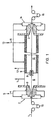
- FIG. 1 is a diagram of a system for the treatment of products 1 - such as spinning belts - shown, consisting of a passage 2 in a wall 3 with supply channels 4 for air as a means 5, an antechamber 6 with discharge channel 7 for the air, one Lock 8, a space 10 protected by thermal insulation 9, a chamber with supply line 11 and discharge line 12 for the medium 13 (steam) and a passage 14 with supply line 11 for steam.
- the spinning belt 1 is introduced by the feed mechanism 15, freely suspended, through passage 2 into the pre-chamber 6, from where it passes through the lock 8 into the chamber 10, where it is treated with the medium 13, among other things.
- the take-off of the spinning belt 1 is carried out freely suspended via passage 14 by means of take-off mechanism 16.
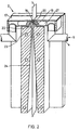
- a passage 2 is drawn in detail in FIG. 2.
- the passage consists of a head 17 with an elongated slot 18 for the central spinning belt 1, which has at the edges entry points 19 of feeders 20 oriented in the direction of the chamber 10, approximately parallel to the main plane of symmetry, in the form of Laval nozzles for generating the supersonic speed, which is via distributors 21 and feed channels 4 are fed from a container (not shown) with means 5.
- the slot 18 with feeds 20 on both sides opens into a convergent section 22 for the compression surges, which in turn is followed by a straight section 23 with a constant cross section for calming the subsonic flow, which in turn is followed by a diffuser 24.
- FIG. 3 An asymmetrical passage 25 is shown in FIG. 3, in which the spinning belt 1 lies directly against a side 26 of the passage 25 which does not contain a feed 20.
- FIG. 4 also shows an asymmetrical passage 27 in which the less durable spinning belt 1 is guided from a certain point in a separate channel 28, the actual passage 27 acting as a seal as usual and at the same time the supply of agent 5 as a medium 13 serves.
Landscapes
- Engineering & Computer Science (AREA)
- General Engineering & Computer Science (AREA)
- Mechanical Engineering (AREA)
- Textile Engineering (AREA)
- Treatment Of Fiber Materials (AREA)
- Chairs For Special Purposes, Such As Reclining Chairs (AREA)
- Advancing Webs (AREA)
- Sealing Devices (AREA)
Description
- Die Erfindung betrifft ein Verfahren zum Abdichten eines Durchganges für eine Förderung von vorzugsweise endlosen Produkten-wie Fasern oder Folienbänder-durch eine Wand in einen Raum, welcher durch ein darin enthaltendes dampf- oder gasförmiges Medium einen zum Außendruck vor der Wand unterschiedlichen Druck besitzt und eine Vorrichtung zur Durchführung des Verfahrens.
- Zur Erzielung bestimmter Produkteigenschaften von Fasern und Folienbändern sind Verfahrensstufe-wie Verstreckung, Dämpfung oder Relaxation-erforderlich, die bei Dampftemperaturen von 100°C bis 150°C unter einem Druck von 1-2,5 bar in einer geschlossenen Kammer durchgeführt werden. Andererseits fallen diese endlosen Produkte meist kontinuierlich an, so daß eine unmittelbare Weiterbehandlung in wirtschaftlicher und qualitätsmäßiger Hinsicht von Vorteil ist. Dabei entstehen bei der Ein- und Ausführung der Produkte in die unter Überdruck stehende Kammer Verluste durch den in die Umgebung austretenden Dampf, die unerwünscht sind.
- Bekannt sind Walzen- oder Labyrinthdichtungen, bei denen das Produkt zwischen mehr oder minder nachgiebigen Sperren in die Kammer ein-oder ausgeführt wird (s. z. B. DE-B-2 633 981). Der Nachteil dieser Vorrichtungen besteht darin, daß neben einer unvollständigen Absperrung und hohem Verschleiß vor allen Dingen Produktschädigungen eintreten können.
- Aufgabe der Erfindung ist es, eine Abdichtung zu finden, die beim Durchtritt eines vorzugsweise berührungslos und kontinuierlich gegörderten Produktes durch eine Wand einen Fluß eines unter Überdruck stehenden Dampfes bzw. Gases von einer zur anderen Seite verhindert, einen Verschleiß der Vorrichtung weitgehend vermeidet, eine schnelle Anpaßbarkeit an verschiedene Betriebsbedingungen erlaubt, eine Beschädigung des Produkts ausschließt und eine einfache Wartung ermöglicht.
- Die Aufgabe wird erfindungsgemäß dadurch gelöst, daß eine im Durchgang nahezu parallel zum Förderweg und in Richtung des höheren Druckes fließende Strömung aus einem dampf-oder gasförmigen Mittel mit einer Geschwindigkeit eingeleitet wird, die anschließend durch teilweise Reduzierung auf dem weiteren räumlich begrenzten Weg in einen solchen Druck umgesetzt wird, der dem entgegenstehenden Druck in dem Raum etwa entspricht und daß an der Eintrittsstelle des Mittels in dem räumlich begrenzten Weg der Druck über die Geschwindigkeit so eingestellt wird, daß er etwa dem Vordruck vor der Wand entspricht.
- Durch das erfindungsgemäße Verfahren ist es möglich ein endloses Produkt ohne kontaktieren von Konstruktionselementen durch eine geschlossene Wand zwischen zwei Räumen mit unterschiedlichem Druck hindurchzufördern, ohne daß beispielsweise die teuren Medien zur Behandlung wie Gase oder Dampf in Folge des Druckgefälles durch diesen Durchgang entweichen, wodurch hohe Kosten bzw, eine starke Belastung der Umwelt vermieden wird. Schon durch das Einleiten geringer Mengen an Mittel kann ein Abfließen des Mediums bei den in der Produktion vorkommenden Druckunterschiede von 0,1-5 bar, insbesondere 1-2,5 bar, vermieden werden. Wenn die Berührung der flachen Bänder mit den Durchgangswänden vermieden werden soll, haben sich Weiten zwischen dem 1,2 bis 5-fachen, insbesondere zwischen dem 1,5 bis 3-fachen, der Banddicke als günstig herausgestellt, wobei Folienbänder gegenüber Faserbändern im allgemeinen kleinere Weiten benötigen.
- Durch Beschleunigung des Mittels in einer Lavaldüse werden an der Eintrittsstelle Geschwindigkeiten zwischen 1 bis 3 Mach oder auch höher erreicht, die einerseits erlauben einen Druck einzustellen, der dem Außendruck (normalerweise 1 atü) im Bereich vor dem Durchgang entspricht und andererseits durch Rückgewinnung der kinetischen Energie einen solchen Druck am Ende des Durchganges aufzubauen, wie er für die Behandlung des Produktes in der Kammer erforderlich ist. Sobald kein Druckgefälle zu den benachbarten Räumen mehr vorhanden ist, wirkt der Durchgang wie eine Sperre.
- Durch Verdichtungsstöße in einem nach der Eintrittsstelle folgenden konvergenten Abschnitt mit geringer Neigung (5° wird der Druck verlustarm-bezogen auf den Diffusor mit hohen Reibungsverlusten-auf kurzem Wege zurückgewonnen, wobei die ursprünglich schrägen Verdichtungsstöße spätestens im folgenden geraden Abschnitt mit einer Länge bis zu 20 mm, insbesondere bis zu 14 mm in geraden Verdichtungsstößen auslaufen, um nach Unterschreiten der Schallgrenze in diesem Abschnitt noch beruhigt zu werden. Die Druckrückgewinnung wird so ausgelegt, daß der Wirkungsgrad der konvergierenden Strömung zwischen 0,4 bis 0,8, vorzugsweise zwischen 0,7 bis 0,8 liegt, wobei unter Wirkungsgrad zu verstehen ist:
- Am Ende des Durchganges wird die Strömung in einem Diffusor bei gleichzeitiger Anpassung an den Druck in der Kammer beruhigt, wobei in rechteckigen Querschnitten ein Winkel von 5-8° und in runden Querschnitten ein Winkel von 610° keinen nachteiligen Einfluß der Strömung auf das Spinnband mehr ausgeübt wird.
- Wenn das Mittel mit einem Impulsstrom m ·v1 mit m=Massestrom und V1 =Gasgeschwindigkeit an der Eintrittsstelle versehen wird, der das 0,4-0,8-fache, vorzugsweise 0,60,75-fache des Produktes aus A3 - P4 mit A3 kleinster Querschnitt des Diffusors und P4=Druck des Mediums in der Kammer beträgt, läßt sich beispielsweise bei Vorgabe der anderen Daten ein Querschnitt A3 ermitteln, bei dem sich eine einwandfreie Strömung unter optimaler Druckumsetzung ausbilden kann.
- Durch Einsatz eines Mittels zum Abdichten, welches auch in der Kammer als Medium verwendet wird, treten keine Mischungsprobleme in der Kammer auf. Die Rückgewinnung des Mittels für das Fahren in einem Kreislauf wird vereinfacht, was wesentliche Vorteile bei umweltschädigenden Mitteln bzw. Medien bringt.
- Weiter können durch Einsatz von Mitteln mit gegenüber dem Medium größerem Molekulargewicht die Impulskräfte vergrößert werden, so daß dann schon kleine Mengen bzw. geringere Geschwindigkeiten des Mittels zum Abdichten ausreichen.
- Durch Abdichten in zwei Stufen ist es möglich, zuerst mit einem billigen Mittel den Druck in einer Schleuse anzuheben, um dann mit einem Medium, welches zur Behandlung der Produkte in der Kammer eingesetzt wird, bei nur wegen des geringen Druckunterschiedes kleinen Mengeneinsatzes den zweiten Durchgang zu sperren.
- In einer erfindungsgemäßen Vorrichtung wird die Aufgabe dadurch gelöst, daß im Randbereich des Durchganges in der Wand Zuführungen für das Mittel angeordnet sind, die in Richtung des Durchganges zeigen, der mindestens im letzten Abschnitt divergent ausgebildet ist.
- Die erfindungsgemäße Vorrichtung erlaubt eine einwandfreie Abdichtung über einen Luftstrom, in dem das Produkt ohne Berührung mit festen Teilen verschleißfrei durch eine Wand einer geschlossenen Kammer geführt werden kann, ohne daß das dort unter höherem Druck vorhandene Medium den Durchgang passieren kann. Die lichten Abmessungen des Durchganges sind entsprechend den praktischen Erfordernissen einstellbar. Sie hängen beispielsweise davon ab, ob das Band glatt oder flauschig ist. Ein besonderer Vorteil ist die verhältnismäßig kurze Bauart, die einen Einbau in jede Wand erlaubt. Die Wartung ist insbesondere wegen fehlender drehender Teile sehr einfach.
- Mit Hilfe der beanspruchten Lavaldüse kann jede geforderte Schall- bzw. Überschallgeschwindigkeit erzeugt werden. Die Zuführungen münden in einen konvergenten Abschnitt, der durch Verdichtungsstoße für eine verlustarme schnelle Umsetzung der kinetischen Energie in den geforderten Bereich sorgt. Während im kurzen anschließenden Abschnitt mit gleichem Querschnitt das Mittel schnell beruhigt wird.
- Als Mittel können mit einem Druck von 1-10 atü Dampf, inerte (Stickstoff, Edelgase) oder andere Gase (Luft, Formiergas) eingesetzt werden, wobei als Mittel ein Stoff bevorzugt wird, der gleichzeitig als Medium zur kontinuierlichen Behandlung von faserförmigen Produkten wie Verstreckung, Relaxierung, Fixierung oder Formgebung verwendet werden kann.
- Beispiele der Erfindung sind in den Zeichnungen dargestellt und werden im folgenden näher beschrieben. Es zeigen:
- Fig. 1 Schema einer Anlage mit Durchgängen
- Fig. 2 Schnitt durch einen Durchgang
- Fig. 3 Ausschnitt durch einen Durchgang
- Fig. 4 Ausschnitt durch einen Durchgang
- In Fig. 1 ist ein Schema einer Anlage zur Behandlung von Produkten 1-wie Spinnbänder--dargestellt, die aus einem Durchgang 2 in einer Wand 3 mit Zuführkanälen 4 für Luft als Mittel 5, einer Vorkammer 6 mit Abführkanal 7 für die Luft, einer Schleuse 8, einem durch Wärmedämmung 9 geschützten Raum 10, einer Kammer mit Zuleitung 11 und Ableitung 12 für das Medium 13 (Dampf) und einem Durchgang 14 mit Zuleitung 11 für Dampf besteht.
- Das Spinnband 1 wird durch Lieferwerk 15 frei schwebend über Durchgang 2 in die Vorkammer 6 eingeführt, von wo es über Schleuse 8 in die Kammer 10 gelangt wo es unter anderem mit dem Medium 13 behandelt wird. Der Abzug des Spinnbandes 1 erfolgt frei schwebend über Durchgang 14 mittels Abzugswerk 16.
- In Fig. 2 ist ein Durchgang 2 im Detail gezeichnet. Der Durchgang besteht aus einem Kopf 17 mit länglichem Schlitz 18 für das mittig laufende Spinnband 1, der an den Rändern Eintrittsstellen 19 von in Richtung der Kammer 10 etwa parallel zur Hauptsymmetrieebene ausgerichtete Zuführungen 20 in Form von Lavaldüsen zur Erzeugung der Überschallgeschwindigkeit besitzt, die über Verteiler 21 und Zuführkanäle 4 aus einem (nicht dargestellten) Behälter mit Mittel 5 gespeist werden. Der Schlitz 18 mit beidseitigen Zuführungen 20 mündet in einem konvergenten Abschnitt 22 für die Verdichtungsstöße, an den sich wiederum ein gerader Abschnitt 23 mit gleichbleibendem Querschnitt zur Beruhigung der Unterschallströmung anschließt, welchem wiederum ein Diffusor 24 folgt.
- In Fig. 3 ist ein asymmetrischer Durchgang 25 gezeigt, bei dem das Spinnband 1 direkt an einer Seite 26 des Durchganges 25, die keine Zuführung 20 enthält, anliegt.
- In Fig. 4 ist ebenfalls ein asymmetrischer Durchgang 27 dargestellt, bei dem das wenig strapazierfähige Spinnband 1 ab einem bestimmten Punkt in einem gesonderten Kanal 28 geführt wird, wobei der eigentliche Durchgang 27 wie üblich als Abdichtung wirkt und gleichzeitig der Zufuhr von Mittel 5 als Medium 13 dient.
Claims (15)
Applications Claiming Priority (2)
| Application Number | Priority Date | Filing Date | Title |
|---|---|---|---|
| DE3609858 | 1986-03-22 | ||
| DE19863609858 DE3609858A1 (de) | 1986-03-22 | 1986-03-22 | Abdichtung von apparaten bei kontinuierlicher produktfoerderung |
Publications (3)
| Publication Number | Publication Date |
|---|---|
| EP0243628A2 EP0243628A2 (de) | 1987-11-04 |
| EP0243628A3 EP0243628A3 (en) | 1988-10-26 |
| EP0243628B1 true EP0243628B1 (de) | 1990-05-09 |
Family
ID=6297127
Family Applications (1)
| Application Number | Title | Priority Date | Filing Date |
|---|---|---|---|
| EP87103380A Expired - Lifetime EP0243628B1 (de) | 1986-03-22 | 1987-03-10 | Abdichtung von Apparaten bei kontinuierlicher Produktförderung |
Country Status (5)
| Country | Link |
|---|---|
| US (2) | US4794751A (de) |
| EP (1) | EP0243628B1 (de) |
| JP (1) | JPS62250267A (de) |
| DE (2) | DE3609858A1 (de) |
| ES (1) | ES2014443B3 (de) |
Families Citing this family (8)
| Publication number | Priority date | Publication date | Assignee | Title |
|---|---|---|---|---|
| US4795856A (en) * | 1987-03-04 | 1989-01-03 | Aluma-Form, Inc. | Apparatus for supporting fiber optic or related cable |
| IT1215659B (it) * | 1988-01-05 | 1990-02-22 | Nuovo Pignone Spa | Modulatore perfezionato per il comando di ratiere rotative ad altissima velocita'. |
| WO1994010368A1 (en) * | 1992-11-02 | 1994-05-11 | Pietro Alberto | Improvements in continuous decatizing of fabrics in autoclave |
| IT1262244B (it) * | 1993-11-30 | 1996-06-19 | Danieli Off Mecc | Piastra a tenuta idrodinamica e supporto idrostatico per impianti di decapaggio e/o di trattamenti chimici e/o di lavaggio per nastro metallico |
| JP4172089B2 (ja) * | 1999-05-17 | 2008-10-29 | 東レ株式会社 | ノンコートエアバッグ用基布およびその製造方法 |
| BE1016493A3 (nl) * | 2005-04-13 | 2006-12-05 | Wiele Michel Van De Nv | Inrichting voor het moduleren van een eerste roterende beweging van een inkomende as naar een tweede, verschillend van de eerste, roterende beweging van een uitgaande as bij textielmachines. |
| US8718784B2 (en) * | 2010-01-14 | 2014-05-06 | Nano-Retina, Inc. | Penetrating electrodes for retinal stimulation |
| FR3126714B1 (fr) * | 2021-09-06 | 2023-09-08 | Staubli Sa Ets | Machine de formation de la foule pour un métier à tisser et son procédé de réglage |
Family Cites Families (14)
| Publication number | Priority date | Publication date | Assignee | Title |
|---|---|---|---|---|
| GB1193625A (en) * | 1966-07-21 | 1970-06-03 | Courtaulds Ltd | Textile Crimping Process. |
| US3475034A (en) * | 1966-02-24 | 1969-10-28 | Chikara Hayashi | Gas-tight seal |
| US3742695A (en) * | 1969-06-25 | 1973-07-03 | R Conrad | Thermoplastic yarn plasticizing device and method of plasticizing thermoplastic yarn |
| FR2157408A5 (de) * | 1971-10-11 | 1973-06-01 | Asahi Chemical Ind | |
| US3868104A (en) * | 1973-07-26 | 1975-02-25 | Little Inc A | Contactless fluid seal |
| JPS5240680A (en) * | 1975-09-22 | 1977-03-29 | Santo Tekkosho Kk | Pressure sealing device for high pressure steamer |
| US4452160A (en) * | 1978-07-19 | 1984-06-05 | Teijin Limited | Method of manufacturing a cut pile carpet |
| CH639707A5 (de) * | 1979-08-16 | 1983-11-30 | Staeubli Ag | Rotationsschaftmaschine. |
| US4290378A (en) * | 1979-08-31 | 1981-09-22 | Monsanto Company | Twisted singles carpet yarn |
| US4408446A (en) * | 1979-08-31 | 1983-10-11 | Monsanto Company | Singles carpet yarn |
| FR2521044A1 (fr) * | 1982-02-11 | 1983-08-12 | Stephanois Rech Mec | Dispositif pour l'introduction et/ou le retrait d'une maniere etanche, de solides a travers au moins un orifice d'une enceinte de traitement a basse pression notamment |
| DE3231171C1 (de) * | 1982-08-21 | 1983-05-19 | M.A.N. Maschinenfabrik Augsburg-Nürnberg AG, 4200 Oberhausen | Sperrfluessigkeitsdichtung |
| DE3278209D1 (en) * | 1982-12-03 | 1988-04-14 | Sulzer Ag | Loom dobby |
| DE3462156D1 (en) * | 1983-10-07 | 1987-02-26 | Staeubli Ag | Lifting device for a rotary dobby |
-
1986
- 1986-03-22 DE DE19863609858 patent/DE3609858A1/de not_active Withdrawn
-
1987
- 1987-03-10 DE DE8787103380T patent/DE3762675D1/de not_active Expired - Lifetime
- 1987-03-10 ES ES87103380T patent/ES2014443B3/es not_active Expired - Lifetime
- 1987-03-10 EP EP87103380A patent/EP0243628B1/de not_active Expired - Lifetime
- 1987-03-10 US US07/024,015 patent/US4794751A/en not_active Expired - Fee Related
- 1987-03-20 JP JP62064412A patent/JPS62250267A/ja active Pending
- 1987-03-23 US US07/028,963 patent/US4727910A/en not_active Expired - Fee Related
Also Published As
| Publication number | Publication date |
|---|---|
| EP0243628A3 (en) | 1988-10-26 |
| JPS62250267A (ja) | 1987-10-31 |
| US4794751A (en) | 1989-01-03 |
| ES2014443B3 (es) | 1990-07-16 |
| US4727910A (en) | 1988-03-01 |
| DE3762675D1 (de) | 1990-06-13 |
| EP0243628A2 (de) | 1987-11-04 |
| DE3609858A1 (de) | 1987-09-24 |
Similar Documents
| Publication | Publication Date | Title |
|---|---|---|
| EP0081082B1 (de) | Verfahren und Vorrichtung zur Herstellung von Wollefasern | |
| EP0243628B1 (de) | Abdichtung von Apparaten bei kontinuierlicher Produktförderung | |
| DE2731696A1 (de) | Verfahren und vorrichtung zum selektiven feinzerkleinern von teilchen aus brechbarem material | |
| EP0662359A1 (de) | Vorrichtung zum berührungsfreien Abdichten eines Spaltes im Auslauf eines Walzgerüstes | |
| DE102017107246A1 (de) | Einrichtung zum Überführen von stabförmigen Artikeln der Tabak verarbeitenden Industrie | |
| CH422645A (de) | Vorrichtung zum Beschicken eines Transportbandes mit Stäben | |
| DE4429692A1 (de) | Förderer für Produkte, insbesondere Zigarettenpackungen | |
| DE3711777C2 (de) | ||
| EP1710329A1 (de) | Verfahren und Vorrichtung zum Schmelzspinnen und Abkühlen einer Vielzahl von Filamenten | |
| DE2916866C2 (de) | ||
| EP0430144A1 (de) | Verfahren und Vorrichtung zur Minderung der Stickoxid-Konzentration im Abgasstrom von Verbrennungsprozessen | |
| EP0001988B1 (de) | Verfahren und Vorrichtung zum Einführen von laufenden Fäden in eine enge Öffnung mittels eines Gasstrahls | |
| DE102011001639A1 (de) | Vorrichtung zur Oberflächenreinigung bewegter Materialbahnen | |
| DE2628120C2 (de) | Verfahren zum Abscheiden von aufgelösten Faserflocken aus einem Transportluftstrom und Vorrichtungen zur Durchführung des Verfahrens | |
| EP0794022B1 (de) | Verfahren und Vorrichtung sowie Kühlmedium zum Kühlen von walzwarmen Profilen | |
| DE3507936C2 (de) | Verfahren zum Entfernen von Fließmittelfilmen, die einem translatorisch bewegten Band anhaften und Vorrichtung zur Durchführung des Verfahrens | |
| DE882209C (de) | Verfahren und Vorrichtung zur Herstellung eines Faservlieses | |
| DE2039443C3 (de) | Vorrichtung zum Überführen eines textilen Fadens von einer ersten Behandlungszone zu einer zweiten Behandlungszone | |
| DE2049594A1 (de) | Verfahren und Vorrichtung zur Herstellung von Elemeirtarfadenvliesstoff | |
| DE2742945A1 (de) | Einspeisung von verfahrensgasen in ein wirbelrohr | |
| DE957747C (de) | Verfahren und Vorrichtung zum Einbringen von Bergeversatz | |
| DE2619880A1 (de) | Injektor fuer strahlapparate | |
| DE4011884A1 (de) | Verfahren zur herstellung von dickstellenarmen mineralwollefasern | |
| DE19832925A1 (de) | Verfahren und Vorrichtung zum Führen und Stützen eines dünnen Bleches oder Metallbandes | |
| DE1204636B (de) | Verfahren und Vorrichtung zum Mischen von Gasen mit UEberschallgeschwindigkeit |
Legal Events
| Date | Code | Title | Description |
|---|---|---|---|
| PUAI | Public reference made under article 153(3) epc to a published international application that has entered the european phase |
Free format text: ORIGINAL CODE: 0009012 |
|
| 17P | Request for examination filed |
Effective date: 19870310 |
|
| AK | Designated contracting states |
Kind code of ref document: A2 Designated state(s): DE ES FR GB IT NL |
|
| PUAL | Search report despatched |
Free format text: ORIGINAL CODE: 0009013 |
|
| AK | Designated contracting states |
Kind code of ref document: A3 Designated state(s): DE ES FR GB IT NL |
|
| 17Q | First examination report despatched |
Effective date: 19890517 |
|
| GRAA | (expected) grant |
Free format text: ORIGINAL CODE: 0009210 |
|
| AK | Designated contracting states |
Kind code of ref document: B1 Designated state(s): DE ES FR GB IT NL |
|
| GBT | Gb: translation of ep patent filed (gb section 77(6)(a)/1977) | ||
| REF | Corresponds to: |
Ref document number: 3762675 Country of ref document: DE Date of ref document: 19900613 |
|
| ET | Fr: translation filed | ||
| ITF | It: translation for a ep patent filed | ||
| PLBE | No opposition filed within time limit |
Free format text: ORIGINAL CODE: 0009261 |
|
| STAA | Information on the status of an ep patent application or granted ep patent |
Free format text: STATUS: NO OPPOSITION FILED WITHIN TIME LIMIT |
|
| 26N | No opposition filed | ||
| PGFP | Annual fee paid to national office [announced via postgrant information from national office to epo] |
Ref country code: DE Payment date: 19920221 Year of fee payment: 6 |
|
| PGFP | Annual fee paid to national office [announced via postgrant information from national office to epo] |
Ref country code: GB Payment date: 19920302 Year of fee payment: 6 |
|
| PGFP | Annual fee paid to national office [announced via postgrant information from national office to epo] |
Ref country code: ES Payment date: 19920313 Year of fee payment: 6 |
|
| PGFP | Annual fee paid to national office [announced via postgrant information from national office to epo] |
Ref country code: FR Payment date: 19920317 Year of fee payment: 6 |
|
| ITTA | It: last paid annual fee | ||
| PGFP | Annual fee paid to national office [announced via postgrant information from national office to epo] |
Ref country code: NL Payment date: 19920331 Year of fee payment: 6 |
|
| PG25 | Lapsed in a contracting state [announced via postgrant information from national office to epo] |
Ref country code: DE Effective date: 19930119 |
|
| PG25 | Lapsed in a contracting state [announced via postgrant information from national office to epo] |
Ref country code: GB Effective date: 19930310 |
|
| PG25 | Lapsed in a contracting state [announced via postgrant information from national office to epo] |
Ref country code: ES Free format text: LAPSE BECAUSE OF NON-PAYMENT OF DUE FEES Effective date: 19930311 |
|
| ITPR | It: changes in ownership of a european patent |
Owner name: CESSIONE;NYSSEN PETER ROGER |
|
| REG | Reference to a national code |
Ref country code: FR Ref legal event code: TP |
|
| PG25 | Lapsed in a contracting state [announced via postgrant information from national office to epo] |
Ref country code: NL Effective date: 19931001 |
|
| GBPC | Gb: european patent ceased through non-payment of renewal fee |
Effective date: 19930310 |
|
| NLS | Nl: assignments of ep-patents |
Owner name: PETER ROGER NYSSEN TE DORMAGEN, BONDSREPUBLIEK DUI |
|
| NLV4 | Nl: lapsed or anulled due to non-payment of the annual fee | ||
| PG25 | Lapsed in a contracting state [announced via postgrant information from national office to epo] |
Ref country code: FR Effective date: 19931130 |
|
| REG | Reference to a national code |
Ref country code: FR Ref legal event code: ST |
|
| REG | Reference to a national code |
Ref country code: ES Ref legal event code: FD2A Effective date: 19990201 |
|
| PG25 | Lapsed in a contracting state [announced via postgrant information from national office to epo] |
Ref country code: IT Free format text: LAPSE BECAUSE OF NON-PAYMENT OF DUE FEES;WARNING: LAPSES OF ITALIAN PATENTS WITH EFFECTIVE DATE BEFORE 2007 MAY HAVE OCCURRED AT ANY TIME BEFORE 2007. THE CORRECT EFFECTIVE DATE MAY BE DIFFERENT FROM THE ONE RECORDED. Effective date: 20050310 |