EP0243276A1 - Dispositif et élément de manutention-roulage pour conteneurs ou analogues - Google Patents
Dispositif et élément de manutention-roulage pour conteneurs ou analogues Download PDFInfo
- Publication number
- EP0243276A1 EP0243276A1 EP87400942A EP87400942A EP0243276A1 EP 0243276 A1 EP0243276 A1 EP 0243276A1 EP 87400942 A EP87400942 A EP 87400942A EP 87400942 A EP87400942 A EP 87400942A EP 0243276 A1 EP0243276 A1 EP 0243276A1
- Authority
- EP
- European Patent Office
- Prior art keywords
- chassis
- container
- carriage
- deck
- ramp
- Prior art date
- Legal status (The legal status is an assumption and is not a legal conclusion. Google has not performed a legal analysis and makes no representation as to the accuracy of the status listed.)
- Granted
Links
- 238000005096 rolling process Methods 0.000 claims description 24
- 230000000903 blocking effect Effects 0.000 claims description 9
- 125000006850 spacer group Chemical group 0.000 claims description 3
- 238000006073 displacement reaction Methods 0.000 abstract 1
- 240000008042 Zea mays Species 0.000 description 3
- 238000013459 approach Methods 0.000 description 2
- 230000005484 gravity Effects 0.000 description 2
- 235000004443 Ricinus communis Nutrition 0.000 description 1
- 238000005452 bending Methods 0.000 description 1
- 230000000694 effects Effects 0.000 description 1
- 238000000034 method Methods 0.000 description 1
- 238000007790 scraping Methods 0.000 description 1
- 230000011664 signaling Effects 0.000 description 1
- 239000000725 suspension Substances 0.000 description 1
Images


Classifications
-
- B—PERFORMING OPERATIONS; TRANSPORTING
- B66—HOISTING; LIFTING; HAULING
- B66F—HOISTING, LIFTING, HAULING OR PUSHING, NOT OTHERWISE PROVIDED FOR, e.g. DEVICES WHICH APPLY A LIFTING OR PUSHING FORCE DIRECTLY TO THE SURFACE OF A LOAD
- B66F9/00—Devices for lifting or lowering bulky or heavy goods for loading or unloading purposes
-
- B—PERFORMING OPERATIONS; TRANSPORTING
- B65—CONVEYING; PACKING; STORING; HANDLING THIN OR FILAMENTARY MATERIAL
- B65D—CONTAINERS FOR STORAGE OR TRANSPORT OF ARTICLES OR MATERIALS, e.g. BAGS, BARRELS, BOTTLES, BOXES, CANS, CARTONS, CRATES, DRUMS, JARS, TANKS, HOPPERS, FORWARDING CONTAINERS; ACCESSORIES, CLOSURES, OR FITTINGS THEREFOR; PACKAGING ELEMENTS; PACKAGES
- B65D90/00—Component parts, details or accessories for large containers
- B65D90/12—Supports
- B65D90/18—Castors, rolls, or the like; e.g. detachable
-
- B—PERFORMING OPERATIONS; TRANSPORTING
- B60—VEHICLES IN GENERAL
- B60P—VEHICLES ADAPTED FOR LOAD TRANSPORTATION OR TO TRANSPORT, TO CARRY, OR TO COMPRISE SPECIAL LOADS OR OBJECTS
- B60P1/00—Vehicles predominantly for transporting loads and modified to facilitate loading, consolidating the load, or unloading
- B60P1/64—Vehicles predominantly for transporting loads and modified to facilitate loading, consolidating the load, or unloading the load supporting or containing element being readily removable
-
- B—PERFORMING OPERATIONS; TRANSPORTING
- B60—VEHICLES IN GENERAL
- B60P—VEHICLES ADAPTED FOR LOAD TRANSPORTATION OR TO TRANSPORT, TO CARRY, OR TO COMPRISE SPECIAL LOADS OR OBJECTS
- B60P1/00—Vehicles predominantly for transporting loads and modified to facilitate loading, consolidating the load, or unloading
- B60P1/64—Vehicles predominantly for transporting loads and modified to facilitate loading, consolidating the load, or unloading the load supporting or containing element being readily removable
- B60P1/6418—Vehicles predominantly for transporting loads and modified to facilitate loading, consolidating the load, or unloading the load supporting or containing element being readily removable the load-transporting element being a container or similar
- B60P1/6445—Vehicles predominantly for transporting loads and modified to facilitate loading, consolidating the load, or unloading the load supporting or containing element being readily removable the load-transporting element being a container or similar the load-transporting element being shifted only vertically
-
- B—PERFORMING OPERATIONS; TRANSPORTING
- B62—LAND VEHICLES FOR TRAVELLING OTHERWISE THAN ON RAILS
- B62B—HAND-PROPELLED VEHICLES, e.g. HAND CARTS OR PERAMBULATORS; SLEDGES
- B62B5/00—Accessories or details specially adapted for hand carts
- B62B5/0083—Wheeled supports connected to the transported object
-
- B—PERFORMING OPERATIONS; TRANSPORTING
- B62—LAND VEHICLES FOR TRAVELLING OTHERWISE THAN ON RAILS
- B62B—HAND-PROPELLED VEHICLES, e.g. HAND CARTS OR PERAMBULATORS; SLEDGES
- B62B5/00—Accessories or details specially adapted for hand carts
- B62B5/0083—Wheeled supports connected to the transported object
- B62B5/0086—Wheeled supports connected to the transported object arranged independently on either side of the transported load
-
- B—PERFORMING OPERATIONS; TRANSPORTING
- B62—LAND VEHICLES FOR TRAVELLING OTHERWISE THAN ON RAILS
- B62B—HAND-PROPELLED VEHICLES, e.g. HAND CARTS OR PERAMBULATORS; SLEDGES
- B62B5/00—Accessories or details specially adapted for hand carts
- B62B5/0083—Wheeled supports connected to the transported object
- B62B5/0089—Lifting lever on wheels or rollers
-
- B—PERFORMING OPERATIONS; TRANSPORTING
- B64—AIRCRAFT; AVIATION; COSMONAUTICS
- B64D—EQUIPMENT FOR FITTING IN OR TO AIRCRAFT; FLIGHT SUITS; PARACHUTES; ARRANGEMENT OR MOUNTING OF POWER PLANTS OR PROPULSION TRANSMISSIONS IN AIRCRAFT
- B64D9/00—Equipment for handling freight; Equipment for facilitating passenger embarkation or the like
-
- B—PERFORMING OPERATIONS; TRANSPORTING
- B62—LAND VEHICLES FOR TRAVELLING OTHERWISE THAN ON RAILS
- B62B—HAND-PROPELLED VEHICLES, e.g. HAND CARTS OR PERAMBULATORS; SLEDGES
- B62B2202/00—Indexing codes relating to type or characteristics of transported articles
- B62B2202/10—Heavy objects, e.g. ISO-containers
-
- Y—GENERAL TAGGING OF NEW TECHNOLOGICAL DEVELOPMENTS; GENERAL TAGGING OF CROSS-SECTIONAL TECHNOLOGIES SPANNING OVER SEVERAL SECTIONS OF THE IPC; TECHNICAL SUBJECTS COVERED BY FORMER USPC CROSS-REFERENCE ART COLLECTIONS [XRACs] AND DIGESTS
- Y02—TECHNOLOGIES OR APPLICATIONS FOR MITIGATION OR ADAPTATION AGAINST CLIMATE CHANGE
- Y02T—CLIMATE CHANGE MITIGATION TECHNOLOGIES RELATED TO TRANSPORTATION
- Y02T50/00—Aeronautics or air transport
- Y02T50/40—Weight reduction
Definitions
- the apron is articulated to the chassis, at one end of the latter.
- the frame is tilted so that said end is adjacent to the ground, then the deck is fixed to the container. Following this, the deck-chassis angle is varied so that the chassis pivots horizontally while the container is lifted.
- a similar device performs the same operation at the other end of the container.
- the container remains suspended between the two devices each mounted on wheels. As a result, the fixing between the container and each deck undergoes all the efforts of the road. The container undergoes significant bending forces. The resulting wheelbase of the rolling assembly (distance between the axles from one device to another) is excessive.
- the object of the invention is to improve the known device to eliminate the aforementioned drawbacks.
- the device is characterized in that the deck is articulated to a carriage movable along the chassis in a direction transverse to the axis of articulation between the deck and the carriage, the articulation axis being close to one end of the chassis when the carriage is in an extreme position.
- the invention thus provides the means to very easily produce a road assembly (capable of moving at speeds of the order of 100 km / h) with very simple means and very easy to implement, on the basis of a container that does not require any prior fitting other than the fixing means generally imposed by standards.
- the means for adjusting the angle between the apron and the chassis comprise a jack articulated on the apron at a distance from the articulation axis, and at the chassis at a distance from its said end, and the means for adjusting the angle between the deck and the chassis further comprises means for selectively blocking the positioning of the deck relative to the carriage, so that the jack can, once the blocking has been carried out, serve to move the carriage along the chassis-ramp.
- the same cylinder is used to orient the deck relative to the chassis and to move the carriage along the chassis, depending on whether the blocking is achieved or not.
- the means for selectively blocking the pivoting of the apron may comprise at least one removable spacer triangulating the apron and the carriage.
- the aforementioned means can advantageously lock the apron in a position where the chassis makes an angle slightly less than 90 ° with the face concerned of the container when the apron is attached to it.
- the carriage When the deck is locked in this position, the carriage can be moved along the chassis to engage the chassis under the container without friction between the chassis and the container. At the end of this operation, the apron is again maneuvered to let the container rest on the chassis.
- a caster or the like is mounted on the chassis in the vicinity of said end of the latter, this caster being positioned to be in contact with the ground when the apron is in a position suitable for fixing it to one face of the container.
- the device can be approached from the container while the apron is very close to the ground without scraping on the ground.
- the apron can be fixed in a folded position on the chassis with fixing means capable of retaining the chassis in a substantially vertical position against the apron when the apron is fixed to a container.
- the device can take an inactive position in which it is retracted against a face of the container. This is very convenient in a cargo aircraft hold.
- the means for adjusting the angle between the deck and the chassis comprise a jack articulated to the deck and to the carriage at a distance from their mutual articulation axis while a second jack, such as a screw-nut system, extending in the direction transverse to the aforementioned articulation axis, adjustably positions the carriage along the ramp chassis.
- a second jack such as a screw-nut system
- the ramp chassis may include means for mounting it on a vehicle with the possibility of pivoting about an axis parallel to and distant from the axis of articulation between the deck and the carriage.
- the invention relates to a handling-rolling element comprising a device according to the first aspect, the chassis of which is fixed to a running gear.
- the running gear is directionally orientable relative to the chassis.
- the running gear of one of the elements used to support the container comprises two axles which are directionally integral
- the two trains can be oriented so that the axis of their wheels is directed along the length of the container, to move the latter laterally .
- Each handling-rolling element (2) (FIG. 1) consists of a fully rotating steering front end (3) as used for road transport with or without its braking, suspension, boom d hitch (5) and its signaling.
- a ball ring 4 allows the directional orientation of an axle 14, equipped with wheels 15, relative to a ramp-frame (6), generally less than eight feet in length, equipped with two parallel rails and spaced from each other, perpendicular to the axis of the ball ring 4.
- a swivel caster (7) Under a first end of this ramp-frame (6) is fixed a swivel caster (7), forming with the two wheels 15 of the axle 14 a tricycle which allows the manual approach of each handling-rolling element (2) ( Figure 1), the axle 14 being oriented perpendicular to the rails of the chassis 6.
- a carriage (8) sliding freely and longitudinally on the rails of the ramp-frame (6) is equipped at one of its ends with yokes (8.1) to which an apron (9) is articulated, along a horizontal axis (10), transverse to the rails and to the axis of the ball ring 4.
- This apron (9) consisting of a frame is equipped with one or more latches (11) intended to be introduced and fixed in the standardized hole or holes of the front and rear faces of the corner pieces (la) of the containers ( 1).
- This jack (12) is articulated to the deck (9) along a second axis of articulation (19), parallel to the first axis (10) and separated from the latter.
- the bulkhead (9) In the empty road position, the bulkhead (9) generally rests on the sliding carriage (8).
- the sliding carriage (8) - deck (9), deck (9) - jack (12) and jack (12) - chassis-ramp (6) joints form the three vertices of a triangle, two of its sides being long. variable by sliding of the carriage on the ramp-frame and respectively by the action of the jack (12).
- a link (13) ( Figures 3 and 4) or a compass allows to maintain or not the angle made by the deck (9) relative to the sliding carriage (8), that is to say the angle between the bearing surface of the deck on the container and the direction of the rails of the chassis 6 so that this angle will have two preferred values, zero ( see figure 5) and ninety minus X degrees (0 ° and 90 ° -X °).
- X is generally around 10 ° or less (see Figure 3).
- the variation of the platform (9) - chassis-ramp (6) angle causes the variation of the chassis-container angle (1) and exerts a lever arm around the axle (14) on the container (1). (see comparatively Figures 2 and 3).
- a blocking of the sliding of the carriage (8) actuated by the unhooking of the link (13) prohibits any false operation.
- the deposit on the ground is done by applying the reverse process to that described.
- a set of piping and electrical wires is used to connect the handling-rolling elements (2) from the inside or the outside to each other and to the tractor.
- the handling-rolling elements are put in the lifting position and at using the jack (12), the height of each end of the container is adjusted to best take account of the requirements for ground clearance and available height.
- the elements according to the invention also make it possible to load a container on a lowered truck bed.
- One of the elements being initially retracted to one end of the container (as shown in Figure 6), the tray is moved back towards the container.
- An action on the jack makes it possible to bring the wheels of the element to bear on the plate.
- the element is immobilized on the plate thanks to the winch, generally provided on the plate.
- the rear element then the front element are put in the lifting position. Thanks to the winch, the assembly is pulled on the platform, the front element rolling on the platform and the rear element rolling on the ground. If the platform is long, a roller or rolling tube is placed between container and platform to finish advancing on the platform while the rear element is retracted.
- the embodiment shown in Figure 13 incorporates all of the elements of the first embodiment, except the cylinder 12 and the link 13.
- a double-acting cylinder 23 is articulated to the deck 9 along the axis 19 and to the carriage 8 along an axis parallel to the axis 10 and spaced therefrom towards the second end of the chassis 6.
- the jack 23 is permanently mounted where the link 13 was selectively mounted in the embodiment previous.
- the carriage 8 fixedly carries a nut 21 in thread connection with a screw 20 rotatably carried by the chassis-ramp 6.
- the screw 20 is parallel to the rails and extends substantially over the entire length of the chassis.
- a crank 22 makes it possible to rotate the screw 20 to move the carriage 8 along the chassis 6.
Landscapes
- Engineering & Computer Science (AREA)
- Mechanical Engineering (AREA)
- Transportation (AREA)
- Chemical & Material Sciences (AREA)
- Combustion & Propulsion (AREA)
- Aviation & Aerospace Engineering (AREA)
- Structural Engineering (AREA)
- Life Sciences & Earth Sciences (AREA)
- Civil Engineering (AREA)
- Geology (AREA)
- Handcart (AREA)
- Control And Other Processes For Unpacking Of Materials (AREA)
- Auxiliary Methods And Devices For Loading And Unloading (AREA)
- Vending Machines For Individual Products (AREA)
- Vehicle Cleaning, Maintenance, Repair, Refitting, And Outriggers (AREA)
- Load-Engaging Elements For Cranes (AREA)
- Chain Conveyers (AREA)
- Supplying Of Containers To The Packaging Station (AREA)
- Container Filling Or Packaging Operations (AREA)
Abstract
Description
- La présente invention concerne un dispositif de manutention-roulage destiné à être monté sur roues et adapté à soulever une extrémité d'un conteneur et le maintenir en position soulevée pendant un déplacement ou une manutention du conteneur, cet élément comprenant :
- - un châssis,
- - un tablier muni de moyens de fixation amovible à une face d'un conteneur et articulés relativement au châssis, et
- - des moyens pour régler l'angle entre le tablier et le châssis.
- Dans un tel dispositif, le tablier est articulé au châssis, à une extrémité de celui-ci.
- Pour effectuer une manutention, on incline le châssis de façon que ladite extrémité soit adjacente au sol, puis on fixe le tablier au conteneur. A la suite de cela, on fait varier l'angle tablier-châssis de façon que le châssis pivote vers l'horizontale tandis que le conteneur est soulevé. Un dispositif similaire effectue la même opération à l'autre extrémité du conteneur. Pendant le déplacement qui suit, le conteneur reste suspendu entre les deux dispositifs montés chacun sur roues. Il en résulte que la fixation entre le conteneur et chaque tablier subit tous les efforts de la route. Le conteneur subit des efforts importants en flexion. L'empattement de l'ensemble roulant qui en résulte (distance entre les essieux d'un dispositif à l'autre) est excessif.
- Le but de l'invention est de perfectionner le dispositif connu pour en éliminer les inconvénients précités.
- Suivant l'invention, le dispositif est caractérisé en ce que le tablier est articulé à un chariot déplaçable le long du châssis selon une direction transversale à l'axe d'articulation entre le tablier et le chariot, l'axe d'articulation étant voisin d'une extrémité du châssis lorsque le chariot est en une position extrême.
- Ainsi, lorsque le levage du conteneur est terminé, on déplace le chariot le long du châssis pour engager le châssis sous le conteneur et on fait en sorte que le conteneur repose sur le châssis pendant le déplacement routier, la manutention, etc... Le conteneur subit donc des efforts nettement moins défavorables. De plus, l'engagement du châssis sous le conteneur à chaque extrémité de celui-ci réduit l'empattement de l'ensemble et le ramène à une valeur acceptable au regard des valeurs maximales autorisées. L'invention procure ainsi le moyen de réaliser très facilement un ensemble routier (capable de se déplacer à des vitesses de l'ordre de 100 km/h) avec des moyens très simples et très faciles à mettre en oeuvre, sur la base d'un conteneur ne nécessitant aucun aménagement préalable autre que les moyens de fixation généralement imposés par les normes.
- De préférence, les moyens pour régler l'angle entre le tablier et le châssis comprennent un vérin articulé au tablier à distance de l'axe d'articulation, et au châssis à distance de sa-dite extrémité, et les moyens pour régler l'angle entre le tablier et le châssis comprennent en outre des moyens pour bloquer sélectivement le positionnement du tablier par rapport au chariot, de façon que le vérin puisse, une fois le blocage effectué, servir à déplacer le chariot le long du châssis-rampe.
- Ainsi, le même vérin sert à orienter le tablier par rapport au châssis et à déplacer le chariot le long du châssis, selon que le blocage est réalisé ou non.
- Les moyens pour bloquer sélectivement le pivotement du tablier peuvent comprendre au moins une entretoise amovible triangulant le tablier et le chariot.
- Les moyens précités peuvent avantageusement bloquer le tablier dans une position où le châssis fait un angle légèrement inférieur à 9O° avec la face concernée du conteneur lorsque le tablier est fixé à celle-ci.
- Lorsque le tablier est bloqué dans cette position, le chariot peut être déplacé le long du châssis pour engager le châssis sous le conteneur sans qu'il y ait frottement entre châssis et conteneur. A la fin de cette opération, le tablier est à nouveau manoeuvré pour laisser le conteneur reposer sur le châssis.
- De préférence, une roulette ou analogue est montée sur le châssis au voisinage de ladite extrémité de celui-ci, cette roulette étant positionnée pour être en contact avec le sol lorsque le tablier est en position propre à sa fixation sur une face du conteneur.
- Grâce à cette roulette, le dispositif peut être approché du conteneur alors que le tablier est très près du sol sans qu'il y ait raclement sur le sol.
- Avantageusement, le tablier peut être fixé dans une position rabattue sur le châssis avec des moyens de fixation capables de retenir le châssis en position sensiblement verticale contre le tablier lorsque le tablier est fixé à un conteneur.
- Ainsi le dispositif peut prendre une position inactive dans laquelle il est escamoté contre une face du conteneur. Ceci est très commode dans une cale d'avion cargo.
- Dans un autre mode de réalisation des moyens pour régler l'angle entre le tablier et le châssis, ces derniers comprennent un vérin articulé au tablier et au chariot à distance de leur axe d'articulation mutuel tandis qu'un second vérin, tel qu'un système vis-écrou, s'étendant selon la direction transversale à l'axe d'articulation précité, positionne de manière réglable le chariot le long du châssis-rampe. De la sorte, il n'y a plus d'entretoise amovible à manipuler, et les efforts de déplacement du chariot sont parallèles à la direction de ce déplacement, ce qui réduit les contraintes et élimine les problèmes liés aux risques de coincement.
- Le châssis-rampe peut comporter des moyens pour son montage sur un véhicule avec possiblité de pivotement autour d'un axe parallèle à et distant de l'axe d'articulation entre le tablier et le chariot.
- Selon un autre aspect, l'invention concerne un élément de manutention-roulage comprenant un dispositif selon le premier aspect dont le châssis est fixé à un train roulant.
- De préférence, le train roulant est orientable directionnellement par rapport au châssis.
- Si le train roulant de l'un des éléments utilisés pour supporter le conteneur comprend deux essieux solidaires directionnellement, les deux trains peuvent 6re orientés de façon que l'axe de leurs roues soit dirigé selon la longueur du conteneur, pour déplacer celui-ci latéralement.
- Ainsi, en utilisant tout ou partie des particularités ci-dessus, on peut à l'aide de deux éléments de manutention-roulage identiques ou non :
- - prendre un conteneur posé au sol,
- - élever celui-ci jusqu'à 1,6 m du sol environ et ce, en conservant ou non l'horizontalité de la charge,
- - déplacer le conteneur en toutes positions du mouvement précédent, autorisant par exemple le chargement en avion de transport militaire,
- - positionner rapidement et avec précision le conteneur dans les trois axes sur tout terrain carrossable,
- - placer les deux éléments de manutention-roulage, sous le conteneur, pour constituer une remorque routière,
- - régler l'empattement et la position des essieux en vue de la meilleure répartition des charges,
- - Etre tracté ou poussé indifféremment d'un sens ou de l'autre par un véhicule,
- - être tracté et poussé conjointement par deux véhicules, réserve étant faite que l'un des deux éléments de manutention-roulage soit à double essieux pour empêcher que le centre de gravité de la remorque sorte de son polygône de sustentation,
- - tracter les éléments indépendemment, ou l'un derrière l'autre pour les déplacer à vide,
- - placer les deux éléments de manutention-roulage en bout de conteneur dans l'équivalent volume d'un conteneur de 10 pieds (1 D.), c'est-à-dire deux fois cinq pieds de long,
- - s'auto-positionner sur un plateau routier à l'aide d'un roule (tube rond) et d'un mini treuil,
- - aller poser un petit conteneur sur un grand plateau ferroviaire, à partir d'un quai à niveau mais latéral au wagon.
- D'autres particularités et avantages de l'invention ressortiront encore de la description non limitative ci-après.
- Aux dessins annexés
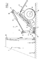
- - la figure 1 est une vue en élévation d'un élément de manutention roulage en position tricycle, en train d'être approché d'un conteneur ;
- - les figures 2, 3, 4, 5 et 6 sont des vues analogues à la figure 1 mais montrant respectivement l'arrimage du conteneur, la position de levage, la position de réglage de l'empattement, la position route et la position escamotée ;
- - la figure 7 est une vue en élévation à plus petite échelle en cours de manutention ;
- - les figures 8 à 12 montrent les cinq étapes du chargement d'un conteneur à bord d'un avion
- - la figure 13 est une vue analogue à la figure 1, mais concernant un second mode de réalisation.
- Chaque élément de manutention-roulage (2) (figure 1) est constitué d'un avant-train directeur (3) à rotation totale tel qu'utilisé pour le transport routier avec ou sans son système de freinage, de suspension, sa flèche d'attelage (5) et sa signalisation. Un rond à billes 4 permet l'orientation directionnelle d'un essieu 14, équpé de roues 15, par rapport à un châssis-rampe (6), d'une longueur en général inférieure à huit pieds, équipé de deux rails parallèles et écartés l'un de l'autre, perpendiculaires à l'axe du rond à billes 4.
- Sous une première extrémité de ce châssis-rampe (6) est fixée une roulette pivotante (7), formant avec les deux roues 15 de l'essieu 14 un tricycle qui permet l'approche manuelle de chaque élément de manutention-roulage (2) (figure 1), l'essieu 14 étant orienté perpendiculairement aux rails du châssis 6.
- Un chariot (8) coulissant librement et longitudinalement sur les rails du châssis-rampe (6) est équipé à l'une de ses extrémités de chapes (8.1) auxquelles un tablier (9) est articulé, selon un axe horizontal (10), transversal aux rails et à l'axe du rond à billes 4.
- Ce tablier (9) constitué d'un cadre est équipé d'un ou plusieurs verrous (11) prévus pour s'introduire et se fixer dans le ou les trous normalisés des faces avant et arrière des pièces de coin (la) des conteneurs (1).
- A la seconde extrémité du châssis-rampe (6) est positionné le point de fixation articulé (18) d'un vérin simple ou double (12) éventuellement télescopique. Ce simple ou double vérin (12) est à double effet.
- L'autre extrémité de ce vérin (12) est articulée au tablier (9) selon un second axe d'articulation (19), parallèle au premier axe (10) et écarté de celui-ci.
- En position route à vide, le tablier (9) repose en général sur le chariot (8) coulissant.
- Les articulations chariot (8) coulissant - tablier (9), tablier (9) - vérin (12) et vérin (12) - châssis-rampe (6) forment les trois sommets d'un triangle dont deux de ses côtés sont de longueur variable par coulissement du chariot sur le châssis-rampe et respectivement par action du vérin (12).
- Une biellette (13) (figures 3 et 4) ou un compas permet de maintenir ou non l'angle que fait le tablier (9) par rapport au chariot (8) coulissant, c'est-à-dire l'angle entre le plan d'appui du tablier sur le conteneur et la direction des rails du châssis 6 de sorte que cet angle aura deux valeurs privilégiées, zéro (voir figure 5) et quatre vingt dix moins X degrés (0° et 90° -X°). X est en général de l'ordre de 10° ou moins (voir figure 3).
- Selon que l'angle tablier (9) - chariot (8) coulissant est bloqué ou non, l'action du vérin (12) et de la gravité déplace le chariot (8) le long du châssis-rampe (6) ou respectivement fait varier l'angle tablier (9) châssis-rampe (6).
- La variation de l'angle tablier (9) - châssis-rampe (6) entraîne la variation de l'angle chassis-conteneur (1) et exerce un bras de levier autour de l'essieu (14) sur le conteneur (1) (voir comparativement les figures 2 et 3).
- D'autres systèmes utilisent déjà l'action de ce bras de levier pour lever le conteneur (1). L'invention permet en outre de faire glisser l'élément de manutention-roulage (2) sous le conteneur (1), ce qui est possible grâce à la manoeuvre suivante :
- - l'angle de 90° - X° atteint, la biellette (13) de blocage d'angle est placée, (figure 3)
- - l'action du vérin (12) est alors inversée - entraînant le coulissement du chariot (8) sur le châssis-rampe (6), (figures 4 et 5),
- - le coulissement sur le châssis-rampe (6) entraîne le coulissement du conteneur (1) sur l'élément de manutention-roulage (2) ou mieux, le coulissement de l'élément de manutention-roulage (2) sous le conteneur (1) avec roulement des roues (15) sur le sol.
- Au fur et à mesure que le chariot (8) coulissant se rapproche de la verticale de l'axe des roues (15), les efforts de compression exercés sur la biellette (13) diminuent pour s'annuler puis s'inverser en efforts d'allongement de plus en plus important au fur et à mesure que le chariot (8) s'écarte de l'autre côté de l'axe du rond à billes (4), (figure 4).
- Lorsque le chariot (8) arrive en butée, le vérin (12) en rétraction annule les efforts d'allongement exercés sur la biellette (13).
- Il est possible alors de décrocher la biellette (13) avant de supprimer toute pression dans le vérin (12) et sa traction sur le tablier (9). Le conteneur (1) vient se reposer sur l'élément de manutention-roulage (2), (figure 5).
- Un blocage du coulissement du chariot (8) actionné par le décrochement de la biellette (13) interdit toute fausse manoeuvre.
- La position du chariot (8) ayant été inversée par rapport à l'axe du rond à billes (4), le bras de levier utilisé pour lever le conteneur (1) du sol vient plaquer le châssis-rampe (6) sous le conteneur (1). Ainsi le conteneur (1) vient se poser et se verrouiller sur l'élément de manutention-roulage (2).
- La même opération est faite conjointement ou indépendemment avec l'autre élément de manutention-roulage (2) à l'autre extrémité du conteneur (figure 7).
- La dépose au sol se fait en appliquant le processus inverse à celui décrit.
- - Un ensemble de tuyauterie et de fils électriques permet de relier par l'intérieur ou l'extérieur les éléments de manutention-roulage (2) entre eux et au tracteur.
- Comme le montrent les figures 8 à 12, pour charger un conteneur à bord d'un avion de transport dont le panneau de chargement forme un angle important avec le plancher de chargement, on met les éléments de manutention-roulage en position de levage et à l'aide du vérin (12), on règle la hauteur de chaque extrémité du conteneur pour tenir compte au mieux des impératifs de garde au sol et de hauteur disposible.
- Les éléments selon l'invention permettent également de charger un conteneur sur un plateau surbaissé de camion. L'un des éléments étant initialement escamoté à une extrémité du conteneur (comme représenté à la figure 6), le plateau est reculé vers le conteneur. Une action sur le vérin permet d'amener les roues de l'élément en appui sur le plateau. L'élément est immobilisé sur le plateau grâce au treuil, généralement prévu sur le plateau. L'élément arrière, puis l'élément avant sont mis en position de levage. Grâce au treuil, l'ensemble est tiré sur la plateforme, l'élément avant roulant sur la plateforme et l'élément arrière roulant sur le sol. Si la plateforme est longue, un roule ou tube de roulage est placé entre conteneur et plateforme pour finir l'avancement sur la plateforme alors que l'élément arrière est escamoté.
- Le mode de réalisation représenté à la figure 13 reprend l'ensemble des éléments du premier mode de réalisation, excepté le vérin 12 et la biellette 13. Un vérin à double effet 23, est articulé au tablier 9 selon l'axe 19 et au chariot 8 selon un axe parallèle à l'axe 10 et écarté de celui-ci vers la seconde extrémité du châssis 6. En somme, le vérin 23 est monté de manière permanente là ou la biellette 13 était montée de manière sélective dans le mode de réalisation précédent. Par "permanente" on veut dire "ne nécessitant pas de démontage en cours d'utilisation".
- De plus, le chariot 8 porte fixement un écrou 21 en prise de filetage avec une vis 20 portée rotativement par le châssis-rampe 6. La vis 20 est parallèle aux rails et s'étend sensiblement sur toute la longueur du châssis. Une manivelle 22, permet de faire tourner la vis 20 pour déplacer le chariot 8 le long du châssis 6.
- L'élément 2 ainsi constitué s'utilise de la manière suivante :
- Au départ (figure 13), le chariot 8 est en position extrême du côté de la roulette 7, et le vérin 23 règle à 45° environ l'angle entre tablier 11 et chariot 8. Une fois les verrous 11 en place dans les pièces la du conteneur 1, le vérin 23 est mis en fonctionnement à l'extension, jusqu'à ce que l'angle précité soit de 90%-X° On actionne ensuite la manivelle 22 pour déplacer le chariot 8 vers son autre position extrême, tandis que le vérin 23 bloque l'angle. Enfin, l'action du vérin 23 est arrêtée, pour laisser la charge reposer sur le châssis, comme exposé plus haut à propos du mode de réalisation précédent.
- Ce mode de réalisation ne permet pas la position escamotée de la figure 6. Il est par contre de réalisation avantageuse car la vis 20 sollicite le chariot 8 selon la direction de déplacement, donc sans risque de coincement, de sorte que le chariot 8 peut sans problème reposer sur les rails par des patins de grande dimension plutôt que par des galets. Dès lors, le chassis-rampe, qui ne subit plus aucun effort localisé, ni de la part du chariot ni de la part du vérin 12 des figures 1 à 4, peut être fortement allégé.
- 1 - conteneur,
- la. - pièces de coin,
- 2 - élément de manutention-roulage,
- 3 - avant-train directeur,
- 4 - rond à billes,
- 5 - flèche d'attelage,
- 6 - châssis-rampe,
- 7 - roulette pivotante,
- 8 - chariot,
- 8.1 - chape de l'articulation d'un tablier (9)
- 9 - tablier,
- 10 - articulation chariot-tablier,
- 11 - verrous,
- 12 - vérin,
- 13 - biellette,
- 14 - essieux,
- 15 - roues,
- 18 - articulation vérin châssis,
- 19 - articulation tablier vérin.
- 20 - vis
- 21 - écrou
- 22 - manivelle
- 23 - vérin à double effet.
Claims (13)
Priority Applications (1)
| Application Number | Priority Date | Filing Date | Title |
|---|---|---|---|
| AT87400942T ATE48408T1 (de) | 1986-04-24 | 1987-04-23 | Aufnahme- und transportgeraet fuer container o.dgl. |
Applications Claiming Priority (2)
| Application Number | Priority Date | Filing Date | Title |
|---|---|---|---|
| FR8605968A FR2597807B1 (fr) | 1986-04-24 | 1986-04-24 | Dispositif et element de manutention-roulage pour conteneurs ou analogues |
| FR8605968 | 1986-04-24 |
Publications (2)
| Publication Number | Publication Date |
|---|---|
| EP0243276A1 true EP0243276A1 (fr) | 1987-10-28 |
| EP0243276B1 EP0243276B1 (fr) | 1989-12-06 |
Family
ID=9334591
Family Applications (1)
| Application Number | Title | Priority Date | Filing Date |
|---|---|---|---|
| EP87400942A Expired EP0243276B1 (fr) | 1986-04-24 | 1987-04-23 | Dispositif et élément de manutention-roulage pour conteneurs ou analogues |
Country Status (12)
| Country | Link |
|---|---|
| US (2) | US4863334A (fr) |
| EP (1) | EP0243276B1 (fr) |
| JP (1) | JPS63503055A (fr) |
| KR (1) | KR920005668B1 (fr) |
| AT (1) | ATE48408T1 (fr) |
| AU (1) | AU582963B2 (fr) |
| CA (1) | CA1317558C (fr) |
| DE (2) | DE3761086D1 (fr) |
| ES (1) | ES2000162B3 (fr) |
| FR (1) | FR2597807B1 (fr) |
| GR (1) | GR3000245T3 (fr) |
| WO (1) | WO1987006570A1 (fr) |
Cited By (4)
| Publication number | Priority date | Publication date | Assignee | Title |
|---|---|---|---|---|
| EP0362988A3 (en) * | 1988-10-07 | 1990-08-08 | Danish Container Supply Aps | An elevating and transporting device |
| FR2932434A1 (fr) * | 2008-06-16 | 2009-12-18 | Toutenkamion | Dispositif de manutention-roulage pour conteneur ou analogue et procede pour deplacer deux tels dispositifs en l'absence de conteneur |
| CN103879435A (zh) * | 2014-03-08 | 2014-06-25 | 安徽万利达羽绒制品有限公司 | 一种羽绒袋装载车 |
| WO2016116746A1 (fr) * | 2015-01-20 | 2016-07-28 | Hy-Dynamix Limited | Appareil de levage et système pour expédier des conteneurs |
Families Citing this family (45)
| Publication number | Priority date | Publication date | Assignee | Title |
|---|---|---|---|---|
| US5018930A (en) * | 1990-03-12 | 1991-05-28 | Sid Corp., Inc. | Lifting and transporting device |
| US5326214A (en) * | 1991-10-21 | 1994-07-05 | Cmi Corporation | Method and apparatus for handling a cutter or the like |
| NO915086D0 (no) * | 1991-12-23 | 1991-12-23 | Haegglunds Moelv As | Loeftemakanisme for containere o.l. |
| US5316434A (en) * | 1992-05-07 | 1994-05-31 | Harnischfeger Corporation | Apparatus and method for hauling material objects |
| DE4242365A1 (de) * | 1992-12-15 | 1994-06-16 | Krupp Industrietech | Transporteinheit für Brückenteile |
| FR2707277B1 (fr) * | 1993-07-05 | 1995-10-06 | Aerospatiale | Train amovible pour le roulage directif d'une charge. |
| FR2712578B1 (fr) * | 1993-11-16 | 1995-12-22 | Hydro 7 Ind | Dispositif pour la manutention d'un conteneur. |
| US5433576A (en) * | 1994-04-01 | 1995-07-18 | Moore Business Forms, Inc. | Low profile dolly and ramp assembly for a roll |
| US5803699A (en) * | 1996-11-12 | 1998-09-08 | Capitol Tool And Die Co. | Apparatus and method for loading and unloading containers |
| HU222476B1 (hu) * | 1999-10-18 | 2003-07-28 | MIKON Mérnőki, Művészeti és Idegenforgalmi Kft. | Univerzális rakodó konténerek mozgatására |
| USD480857S1 (en) | 2002-04-17 | 2003-10-14 | Saginaw Products Corp. | Modular mobilizer assembly |
| US6832870B1 (en) * | 2002-05-15 | 2004-12-21 | Paul Jules Krivoy | Barrier transporter and positioner |
| US6729817B1 (en) * | 2002-05-23 | 2004-05-04 | Robert J. Fennell | Stackable shipping trailer |
| US6821066B2 (en) * | 2003-04-22 | 2004-11-23 | 21St Century Structures, Llc | Precast concrete panel combination trailer and storage rack assembly |
| US20040219002A1 (en) * | 2003-05-01 | 2004-11-04 | Sonny Lenaers | Transportable manufacturing system |
| USD535454S1 (en) | 2005-03-03 | 2007-01-16 | Cignys, Inc. | Modular mobilizer assembly |
| US20080187424A1 (en) * | 2007-02-06 | 2008-08-07 | Garcia Alberto M | Transport For A Wind Tower And Methods Thereof |
| WO2008104185A1 (fr) * | 2007-02-28 | 2008-09-04 | Vestas Wind Systems A/S | Système porteur d'éléments d'éoliennes, système de transport d'éléments d'éoliennes méthode d'utilisation du système porteur |
| US7866933B2 (en) * | 2008-12-02 | 2011-01-11 | James W. Welch | Container trailer |
| US20100226740A1 (en) * | 2009-03-06 | 2010-09-09 | Humble Erik L | Shipping container handling |
| US9878730B2 (en) * | 2009-06-18 | 2018-01-30 | Angel L. Claudio, Sr. | Dolly for track welder-cutter |
| US8616564B2 (en) * | 2009-12-07 | 2013-12-31 | Paceco Corp. | Cargo container handling cart and system using same |
| US20110176898A1 (en) * | 2010-01-21 | 2011-07-21 | United States Of America As Represented By The Secretary Of The Navy | Shipping container lifting and maneuvering dolly |
| US9120495B1 (en) | 2010-08-23 | 2015-09-01 | Thomas Anderson | Dolly for moving objects |
| US20120201636A1 (en) * | 2011-02-07 | 2012-08-09 | Vestas Wind Systems A/S | Transportation device for a wind turbine component and method of using same |
| NO333058B1 (no) * | 2011-04-06 | 2013-02-25 | Geir Tore Fjetland | Lofteanordning for container |
| NO338223B1 (no) * | 2012-12-05 | 2016-08-08 | Jack Pack As | Løfteanordning for container og fremgangsmåte ved bruk av samme |
| US10391617B1 (en) * | 2015-03-05 | 2019-08-27 | Mark Lloyd | Canopy removal and storage systems and methods |
| US9914467B2 (en) * | 2015-08-14 | 2018-03-13 | Oldcastle Light Building Products, LLC | Attachment and support members for modular building structures |
| US10344487B2 (en) | 2015-08-14 | 2019-07-09 | Oldcastle Light Building Products, LLC | Attachment and support members for modular building structures |
| US10625997B1 (en) * | 2016-04-29 | 2020-04-21 | King Kutter, Inc. | Container mobility lift |
| US10933795B2 (en) * | 2016-10-28 | 2021-03-02 | Saginaw Products Corporation | Intermodal container mobilization |
| US11167682B2 (en) * | 2017-01-11 | 2021-11-09 | Biosphere Aerospace, Llc | Modular container transport systems |
| US10967973B2 (en) | 2017-01-11 | 2021-04-06 | Biosphere Aerospace, Llc | Modular container transport systems |
| US10947036B2 (en) * | 2017-01-11 | 2021-03-16 | Biosphere Aerospace, Llc | Modular container transport systems |
| EP4365124A3 (fr) * | 2017-11-06 | 2024-08-07 | Crown Equipment Corporation | Système de superposition de véhicules industriels |
| US10472166B2 (en) | 2017-11-16 | 2019-11-12 | Dfw Disposal And Recycling Service, Llc | Transportable container with subfloor for use with a roll-off truck |
| RU2765385C1 (ru) * | 2018-05-29 | 2022-01-28 | Шибакаи Ко., Лтд. | Грузовой контейнер |
| US11066257B2 (en) * | 2018-05-31 | 2021-07-20 | Victor Casanova | Container transport system |
| DE102018119396A1 (de) | 2018-08-09 | 2020-02-13 | Airbus Operations Gmbh | Asymmetrisch anhebbare Frachtladeplattform und Frachtladevorrichtung, Frachtcontainer und Flugzeug mit Frachtladeplattform |
| RU192921U1 (ru) * | 2019-06-07 | 2019-10-07 | Чугунов Иван Михайлович | Устройство подъема и перемещения оборудования контейнерного типа |
| CN110271806B (zh) * | 2019-06-24 | 2021-04-06 | 南京机电职业技术学院 | 一种移动体单元及便携式搬运工具 |
| WO2021051207A1 (fr) * | 2019-09-20 | 2021-03-25 | Badiou Daniel | Ensemble roue modulaire pour la manipulation et le transport d'un objet de charge |
| KR20230154036A (ko) | 2021-03-05 | 2023-11-07 | 크라운 이큅먼트 코포레이션 | 레이오버 브래킷 시스템 |
| US12280815B2 (en) * | 2022-08-01 | 2025-04-22 | Toyota Motor Engineering & Manufacturing North America, Inc. | Systems for pod movers |
Citations (3)
| Publication number | Priority date | Publication date | Assignee | Title |
|---|---|---|---|---|
| FR1459243A (fr) * | 1965-10-06 | 1966-04-29 | Sud Aviation | Dispositif de manutention de charges rigides |
| US3497231A (en) * | 1966-11-23 | 1970-02-24 | Gichner Mobile Systems Inc | Demountable running gear with articulated rear axle |
| US3834111A (en) * | 1971-10-07 | 1974-09-10 | Reliance Trailer Mfg Inc | Method for transporting building modules |
Family Cites Families (11)
| Publication number | Priority date | Publication date | Assignee | Title |
|---|---|---|---|---|
| DE872432C (de) * | 1943-02-03 | 1953-04-02 | Suedwerke Motoren Und Kraftwag | Fahrzeug zur Befoerderung schwerer Lasten auf Strassen und im Gelaende |
| US3243193A (en) * | 1964-07-02 | 1966-03-29 | Gichner Mobile Systems Inc | Hydraulically operated demountable running gear |
| DE1904938B1 (de) * | 1969-02-01 | 1970-10-22 | Fries Gmbh Heinrich De | Transportvorrichtung fuer Grossbehaelter |
| FR2109109A5 (fr) * | 1970-10-01 | 1972-05-26 | Saphem | |
| US3795336A (en) * | 1971-10-07 | 1974-03-05 | Reliance Trailer Mfg Inc | Apparatus for transporting building modules |
| DE2154619A1 (de) * | 1971-10-29 | 1973-05-03 | Lohmann & Stolterfoht Ag | Container-transportfahrzeug |
| NZ193308A (en) * | 1979-04-17 | 1983-11-18 | Noyes Bros Pty Ltd | Self loading articulated mobile transporter |
| FR2471944A2 (fr) * | 1979-11-06 | 1981-06-26 | Lebre Charles | Chariot elevateur a surface de roulage et d'elevation variables synchronises |
| US4530411A (en) * | 1983-07-18 | 1985-07-23 | The United States Of America As Represented By The Secretary Of The Army | Motorized wheels for dolly structures |
| SU1220961A1 (ru) * | 1984-04-26 | 1986-03-30 | Государственный Институт По Проектированию,Технологии Монтажа Предприятий Химической Промышленности | Транспортное средство дл перевозки крупногабаритных грузов |
| US4570959A (en) * | 1984-09-13 | 1986-02-18 | The United States Of America As Represented By The Secretary Of The Army | Dolly unit |
-
1986
- 1986-04-24 FR FR8605968A patent/FR2597807B1/fr not_active Expired - Lifetime
-
1987
- 1987-04-23 WO PCT/FR1987/000137 patent/WO1987006570A1/fr not_active Ceased
- 1987-04-23 DE DE8787400942T patent/DE3761086D1/de not_active Expired - Lifetime
- 1987-04-23 US US07/141,362 patent/US4863334A/en not_active Expired - Fee Related
- 1987-04-23 JP JP62502652A patent/JPS63503055A/ja active Granted
- 1987-04-23 CA CA000535320A patent/CA1317558C/fr not_active Expired - Fee Related
- 1987-04-23 KR KR1019870701215A patent/KR920005668B1/ko not_active Expired
- 1987-04-23 AU AU73052/87A patent/AU582963B2/en not_active Ceased
- 1987-04-23 ES ES87400942T patent/ES2000162B3/es not_active Expired - Lifetime
- 1987-04-23 EP EP87400942A patent/EP0243276B1/fr not_active Expired
- 1987-04-23 DE DE198787400942T patent/DE243276T1/de active Pending
- 1987-04-23 AT AT87400942T patent/ATE48408T1/de not_active IP Right Cessation
-
1989
- 1989-06-01 US US07/360,202 patent/US4936733A/en not_active Expired - Fee Related
- 1989-12-07 GR GR89400286T patent/GR3000245T3/el unknown
Patent Citations (3)
| Publication number | Priority date | Publication date | Assignee | Title |
|---|---|---|---|---|
| FR1459243A (fr) * | 1965-10-06 | 1966-04-29 | Sud Aviation | Dispositif de manutention de charges rigides |
| US3497231A (en) * | 1966-11-23 | 1970-02-24 | Gichner Mobile Systems Inc | Demountable running gear with articulated rear axle |
| US3834111A (en) * | 1971-10-07 | 1974-09-10 | Reliance Trailer Mfg Inc | Method for transporting building modules |
Cited By (7)
| Publication number | Priority date | Publication date | Assignee | Title |
|---|---|---|---|---|
| EP0362988A3 (en) * | 1988-10-07 | 1990-08-08 | Danish Container Supply Aps | An elevating and transporting device |
| FR2932434A1 (fr) * | 2008-06-16 | 2009-12-18 | Toutenkamion | Dispositif de manutention-roulage pour conteneur ou analogue et procede pour deplacer deux tels dispositifs en l'absence de conteneur |
| WO2009153521A3 (fr) * | 2008-06-16 | 2010-04-22 | Toutenkamion | Dispositif de manutention-roulage pour conteneur ou analogue et procede pour deplacer deux tels dispositifs en l'absence de conteneur |
| EP2505429A1 (fr) | 2008-06-16 | 2012-10-03 | Toutenkamion | Procédé pour régler l'empattement d'un ensemble roulant comprenant au moins deux dispositifs de manutention-roulage |
| CN103879435A (zh) * | 2014-03-08 | 2014-06-25 | 安徽万利达羽绒制品有限公司 | 一种羽绒袋装载车 |
| CN103879435B (zh) * | 2014-03-08 | 2016-04-13 | 安徽万利达羽绒制品有限公司 | 一种羽绒袋装载车 |
| WO2016116746A1 (fr) * | 2015-01-20 | 2016-07-28 | Hy-Dynamix Limited | Appareil de levage et système pour expédier des conteneurs |
Also Published As
| Publication number | Publication date |
|---|---|
| KR880701209A (ko) | 1988-07-26 |
| JPH0534190B2 (fr) | 1993-05-21 |
| ES2000162B3 (es) | 1990-04-01 |
| AU7305287A (en) | 1987-11-24 |
| DE243276T1 (de) | 1988-02-25 |
| GR3000245T3 (en) | 1991-03-15 |
| FR2597807B1 (fr) | 1990-11-02 |
| CA1317558C (fr) | 1993-05-11 |
| ATE48408T1 (de) | 1989-12-15 |
| FR2597807A1 (fr) | 1987-10-30 |
| US4936733A (en) | 1990-06-26 |
| KR920005668B1 (ko) | 1992-07-13 |
| JPS63503055A (ja) | 1988-11-10 |
| ES2000162A4 (es) | 1987-12-16 |
| WO1987006570A1 (fr) | 1987-11-05 |
| DE3761086D1 (de) | 1990-01-11 |
| AU582963B2 (en) | 1989-04-13 |
| EP0243276B1 (fr) | 1989-12-06 |
| US4863334A (en) | 1989-09-05 |
Similar Documents
| Publication | Publication Date | Title |
|---|---|---|
| EP0243276B1 (fr) | Dispositif et élément de manutention-roulage pour conteneurs ou analogues | |
| EP0584026B1 (fr) | Ensemble d'accouplement entre deux structures wagon successives et un bogie commun | |
| FR2963304A1 (fr) | Systeme universel de chargement/dechargement et de transport ferroviaire de semi-remorques routieres | |
| EP4087772B1 (fr) | Remorque de transport comprenant un système d'inclinaison et de redressement de son plateau | |
| FR2965257A1 (fr) | Systeme de manutention par soulevement d'une remorque | |
| WO1993003945A1 (fr) | Unite dissociable de transport ferroviaire porteuse d'un chargement, notamment d'une unite routiere | |
| FR2899196A1 (fr) | Tracteur pour le transport de receptacles de transport mobiles. | |
| FR2747075A1 (fr) | Systeme de remorquage pour au moins un vehicule tracteur et un vehicule tracte et vehicule automobile pouvant etre utilise dans ce systeme | |
| EP2505429B1 (fr) | Procédé pour régler l'empattement d'un ensemble roulant comprenant au moins deux dispositifs de manutention-roulage | |
| FR3037311A1 (fr) | Dispositif d'accrochage d'une remorque a un vehicule tracteur et ensemble forme par l'attelage d'un vehicule tracteur et d'une remorque comprenant un tel dispositif | |
| EP0424296B1 (fr) | Plan de chargement composite pour véhicule du type porte-voitures | |
| EP4351924A1 (fr) | Ensemble de dépannage-remorquage pour véhicule remorqueur, et véhicule remorqueur le comprenant | |
| EP1495994B1 (fr) | Déchetterie mobile | |
| FR2647731A2 (fr) | Dispositif de manutention-roulage pour conteneurs ou analogues | |
| BE518092A (fr) | ||
| FR2586628A1 (fr) | Convoi routier porte-vehicules a unite de chargement dissociable du chassis cabine | |
| FR2606004A1 (fr) | Systeme de manutention verticale et de remorquage de conteneurs normalises | |
| FR3160646A1 (fr) | Dispositif d’immobilisation rapide d’une roue de véhicule, pour un plateau de support | |
| FR2662651A1 (fr) | Depanneuse. | |
| FR2845639A1 (fr) | Chariot pour la mise en place de roues sur un vehicule lourd, notamment poids lourd | |
| FR2519600A1 (fr) | Perfectionnements aux semi-remorques porte-engin a plateau surbaisse | |
| FR2776978A1 (fr) | Remorque a surface de chargement relevable et abaissable | |
| FR3141900A1 (fr) | Ensemble de dépannage-remorquage perfectionné pour véhicule remorqueur, et véhicule remorqueur le comprenant | |
| FR3112753A1 (fr) | Remorque pour véhicule léger | |
| FR2620676A1 (fr) | Dispositif de remorquage d'un vehicule automobile a l'aide d'un vehicule tracteur, du type comportant deux chariots porteurs independants pour les roues du vehicule a remorquer |
Legal Events
| Date | Code | Title | Description |
|---|---|---|---|
| PUAI | Public reference made under article 153(3) epc to a published international application that has entered the european phase |
Free format text: ORIGINAL CODE: 0009012 |
|
| 17P | Request for examination filed |
Effective date: 19870427 |
|
| AK | Designated contracting states |
Kind code of ref document: A1 Designated state(s): AT BE CH DE ES FR GB GR IT LI LU NL SE |
|
| ITCL | It: translation for ep claims filed |
Representative=s name: BARZANO' E ZANARDO ROMA S.P.A. |
|
| TCAT | At: translation of patent claims filed | ||
| GBC | Gb: translation of claims filed (gb section 78(7)/1977) | ||
| TCNL | Nl: translation of patent claims filed | ||
| DET | De: translation of patent claims | ||
| 17Q | First examination report despatched |
Effective date: 19880912 |
|
| ITF | It: translation for a ep patent filed | ||
| GRAA | (expected) grant |
Free format text: ORIGINAL CODE: 0009210 |
|
| AK | Designated contracting states |
Kind code of ref document: B1 Designated state(s): AT BE CH DE ES FR GB GR IT LI LU NL SE |
|
| REF | Corresponds to: |
Ref document number: 48408 Country of ref document: AT Date of ref document: 19891215 Kind code of ref document: T |
|
| REF | Corresponds to: |
Ref document number: 3761086 Country of ref document: DE Date of ref document: 19900111 |
|
| GBT | Gb: translation of ep patent filed (gb section 77(6)(a)/1977) | ||
| REG | Reference to a national code |
Ref country code: GR Ref legal event code: FG4A Free format text: 3000245 |
|
| PLBE | No opposition filed within time limit |
Free format text: ORIGINAL CODE: 0009261 |
|
| STAA | Information on the status of an ep patent application or granted ep patent |
Free format text: STATUS: NO OPPOSITION FILED WITHIN TIME LIMIT |
|
| 26N | No opposition filed | ||
| ITTA | It: last paid annual fee | ||
| PGFP | Annual fee paid to national office [announced via postgrant information from national office to epo] |
Ref country code: SE Payment date: 19920408 Year of fee payment: 6 |
|
| PGFP | Annual fee paid to national office [announced via postgrant information from national office to epo] |
Ref country code: CH Payment date: 19920414 Year of fee payment: 6 |
|
| PGFP | Annual fee paid to national office [announced via postgrant information from national office to epo] |
Ref country code: GR Payment date: 19920415 Year of fee payment: 6 |
|
| PGFP | Annual fee paid to national office [announced via postgrant information from national office to epo] |
Ref country code: AT Payment date: 19920422 Year of fee payment: 6 |
|
| PGFP | Annual fee paid to national office [announced via postgrant information from national office to epo] |
Ref country code: NL Payment date: 19920430 Year of fee payment: 6 |
|
| EPTA | Lu: last paid annual fee | ||
| PGFP | Annual fee paid to national office [announced via postgrant information from national office to epo] |
Ref country code: GB Payment date: 19930413 Year of fee payment: 7 |
|
| PGFP | Annual fee paid to national office [announced via postgrant information from national office to epo] |
Ref country code: FR Payment date: 19930421 Year of fee payment: 7 |
|
| PG25 | Lapsed in a contracting state [announced via postgrant information from national office to epo] |
Ref country code: AT Effective date: 19930423 |
|
| PG25 | Lapsed in a contracting state [announced via postgrant information from national office to epo] |
Ref country code: SE Effective date: 19930424 |
|
| PG25 | Lapsed in a contracting state [announced via postgrant information from national office to epo] |
Ref country code: LI Effective date: 19930430 Ref country code: CH Effective date: 19930430 |
|
| PGFP | Annual fee paid to national office [announced via postgrant information from national office to epo] |
Ref country code: LU Payment date: 19930430 Year of fee payment: 7 Ref country code: ES Payment date: 19930430 Year of fee payment: 7 |
|
| PGFP | Annual fee paid to national office [announced via postgrant information from national office to epo] |
Ref country code: BE Payment date: 19930602 Year of fee payment: 7 |
|
| PGFP | Annual fee paid to national office [announced via postgrant information from national office to epo] |
Ref country code: DE Payment date: 19930628 Year of fee payment: 7 |
|
| PG25 | Lapsed in a contracting state [announced via postgrant information from national office to epo] |
Ref country code: GR Free format text: THE PATENT HAS BEEN ANNULLED BY A DECISION OF A NATIONAL AUTHORITY Effective date: 19931031 |
|
| PG25 | Lapsed in a contracting state [announced via postgrant information from national office to epo] |
Ref country code: NL Effective date: 19931101 |
|
| NLV4 | Nl: lapsed or anulled due to non-payment of the annual fee | ||
| REG | Reference to a national code |
Ref country code: CH Ref legal event code: PL |
|
| PG25 | Lapsed in a contracting state [announced via postgrant information from national office to epo] |
Ref country code: LU Free format text: LAPSE BECAUSE OF NON-PAYMENT OF DUE FEES Effective date: 19940423 Ref country code: GB Effective date: 19940423 |
|
| PG25 | Lapsed in a contracting state [announced via postgrant information from national office to epo] |
Ref country code: ES Free format text: LAPSE BECAUSE OF NON-PAYMENT OF DUE FEES Effective date: 19940425 |
|
| PG25 | Lapsed in a contracting state [announced via postgrant information from national office to epo] |
Ref country code: BE Effective date: 19940430 |
|
| BERE | Be: lapsed |
Owner name: TOUTENKAMION Effective date: 19940430 |
|
| GBPC | Gb: european patent ceased through non-payment of renewal fee |
Effective date: 19940423 |
|
| PG25 | Lapsed in a contracting state [announced via postgrant information from national office to epo] |
Ref country code: FR Effective date: 19941229 |
|
| REG | Reference to a national code |
Ref country code: GR Ref legal event code: MM2A Free format text: 3000245 |
|
| PG25 | Lapsed in a contracting state [announced via postgrant information from national office to epo] |
Ref country code: DE Effective date: 19950103 |
|
| EUG | Se: european patent has lapsed |
Ref document number: 87400942.6 Effective date: 19931110 |
|
| REG | Reference to a national code |
Ref country code: FR Ref legal event code: ST |
|
| REG | Reference to a national code |
Ref country code: ES Ref legal event code: FD2A Effective date: 19990301 |
|
| PG25 | Lapsed in a contracting state [announced via postgrant information from national office to epo] |
Ref country code: IT Free format text: LAPSE BECAUSE OF NON-PAYMENT OF DUE FEES Effective date: 20050423 |