EP0242142B1 - System zum Zeitsteuerungsabgleich der Signalübertragung zur Vermeidung von Kollisionen - Google Patents
System zum Zeitsteuerungsabgleich der Signalübertragung zur Vermeidung von Kollisionen Download PDFInfo
- Publication number
- EP0242142B1 EP0242142B1 EP87303164A EP87303164A EP0242142B1 EP 0242142 B1 EP0242142 B1 EP 0242142B1 EP 87303164 A EP87303164 A EP 87303164A EP 87303164 A EP87303164 A EP 87303164A EP 0242142 B1 EP0242142 B1 EP 0242142B1
- Authority
- EP
- European Patent Office
- Prior art keywords
- equipment unit
- signal
- terminal equipment
- central
- transmitting
- Prior art date
- Legal status (The legal status is an assumption and is not a legal conclusion. Google has not performed a legal analysis and makes no representation as to the accuracy of the status listed.)
- Expired - Lifetime
Links
- 230000008054 signal transmission Effects 0.000 title claims description 36
- 230000005540 biological transmission Effects 0.000 claims description 83
- 238000005259 measurement Methods 0.000 claims description 40
- 238000004891 communication Methods 0.000 claims description 11
- 238000000034 method Methods 0.000 claims description 8
- 238000012360 testing method Methods 0.000 description 17
- 238000001514 detection method Methods 0.000 description 12
- 238000012545 processing Methods 0.000 description 12
- 238000010586 diagram Methods 0.000 description 11
- 238000006243 chemical reaction Methods 0.000 description 2
- 238000005315 distribution function Methods 0.000 description 2
- 238000010276 construction Methods 0.000 description 1
- 239000000284 extract Substances 0.000 description 1
- 230000000977 initiatory effect Effects 0.000 description 1
- 230000010363 phase shift Effects 0.000 description 1
- 238000011084 recovery Methods 0.000 description 1
- 230000001360 synchronised effect Effects 0.000 description 1
- 230000007704 transition Effects 0.000 description 1
Images


Classifications
-
- H—ELECTRICITY
- H04—ELECTRIC COMMUNICATION TECHNIQUE
- H04J—MULTIPLEX COMMUNICATION
- H04J3/00—Time-division multiplex systems
- H04J3/02—Details
- H04J3/06—Synchronising arrangements
- H04J3/0635—Clock or time synchronisation in a network
- H04J3/0682—Clock or time synchronisation in a network by delay compensation, e.g. by compensation of propagation delay or variations thereof, by ranging
-
- H—ELECTRICITY
- H04—ELECTRIC COMMUNICATION TECHNIQUE
- H04L—TRANSMISSION OF DIGITAL INFORMATION, e.g. TELEGRAPHIC COMMUNICATION
- H04L12/00—Data switching networks
- H04L12/28—Data switching networks characterised by path configuration, e.g. LAN [Local Area Networks] or WAN [Wide Area Networks]
Definitions
- the present invention relates to a signal transmission system in a communication network system wherein one central equipment unit and a plurality of terminal equipment units are connected via a signal transmission line and, more particularly, to a system for adjusting a signal transmission timing at each terminal equipment unit, for the purpose of preventing signal collisions on the signal transmission line.
- a communication network is known, which is constructed such that a terminal equipment unit having concentration and distribution functions is installed in a building or at a floor of the building, at least one terminal device such as a telephone set is connected to the terminal equipment unit, and a plurality of such terminal equipment units are coupled to a central equipment unit such as a PBX (private branch exchange) via an up link and a down link.
- a terminal equipment unit having concentration and distribution functions is installed in a building or at a floor of the building, at least one terminal device such as a telephone set is connected to the terminal equipment unit, and a plurality of such terminal equipment units are coupled to a central equipment unit such as a PBX (private branch exchange) via an up link and a down link.
- PBX private branch exchange
- the terminal equipment units are connected at different positions along the signal transmission line. For this reason, the signal propagation times (transmission delay times) between the respective terminal equipment units and the central equipment unit differ from each other.
- transmission delay times transmission delay times
- simply setting time margins for signal transmissions while taking into consideration the different transmission delay times of the terminal equipment units would considerably reduce the utility efficiency of the transmission line.
- EP-A-0 168 051 discloses a system in which the central unit sends a maintainance polling signal to a terminal unit which is not currently transmitting information to the central unit.
- This system operates in a test mode, a transmission-start timing setting mode, and a normal data transmission mode.
- a central equipment unit transmits test signals addressed to the terminal equipment units, and each terminal equipment unit transmits a response signal to the central equipment unit, in response to the reception of the test signal addressed to itself.
- the central equipment unit measures a delay time between the transmission timing of the test signal and the reception timing of the response signal transmitted from the terminal equipment unit.
- the central equipment unit transmits control data based on the measured delay time to each terminal equipment unit.
- each terminal equipment unit transmits a data signal to the central equipment unit at a timing based on the control data transmitted from the central equipment unit.
- the delay time measurement mode and the data transmission mode are provided independently from each other, if an additional terminal equipment unit is connected to the network, it is difficult to measure a transmission delay time between the additional terminal equipment unit and the central equipment unit. In other words, the delay time between the additional terminal equipment unit and the central equipment unit must be measured when the existing terminal equipment units are not busy.
- the central equipment unit requests each terminal equipment unit to transmit a test signal, and the terminal equipment unit requested to do so, transmits the test signal.
- the central equipment unit sends the test signal, transmitted from the terminal equipment unit, back to the terminal equipment unit, without performing any processing.
- the terminal equipment unit measures a transmission delay time between the transmission timing of the test signal and reception timing of the test signal sent back from the central equipment unit, and adjusts the transmission timing of a data signal for the central equipment unit in accordance with the measured transmission delay time.
- One transmission frame of the system includes a data transmission interval having time slots assigned to the respective terminal equipment units, and a window interval for measuring delay times.
- the window interval includes an address field for designating one of the terminal equipment units to transmit the test signal, and a test signal transmission/receiving field in which a terminal equipment unit transmits a test signal to the central equipment unit and receives the test signal sent back therefrom. Only the test signal transmission/reception field is used to transmit/receive the test signal for delay measurement, and the address field cannot be used therefor. For this reason, a time interval of a delay measurement window must be set relatively long, thus reducing the utility efficiency of time slots for data transmission.
- each terminal equipment unit since each terminal equipment unit must receive a data signal transmitted from the central equipment unit and the test signal transmitted by itself, it is difficult to stably receive these signals. In other words, an expensive receiving device is required to ensure stable reception of the signals.
- an object of the present invention to provide a communication network system capable of improving the utility efficiency of time slots adapted for data transmission to terminal equipment units.
- a first aspect of the invention provides a communication network system comprising; a central equipment unit (1); a plurality of terminal equipment units (21, 22, etc, 2 n ), each having at least one terminal device (5) connected thereto; said central equipment unit (1) and said terminal equipment units 5, being connected by an up link (3) and a down link (4) for transmission of information data between said central equipment unit (6) and said terminal equipment units (5); said central equipment unit (1) having means for providing reference timings and means for transmitting on said down link to a subscriber station a signal comprising an address field designating one of said terminal equipment units (21, 22, Vietnamese,2 n ); said terminal equipment units (21, 22, etc,2 n ) each having means for transmitting on said up link to said central equipment unit (68) a response signal when designated by said address field; and said central equipment unit (1) having means for determining a delay time caused by the propagation time of said signals between said central equipment unit (1) and said designated terminal equipment unit (21, 22, etc,2 n ) and means for transmitting to said designated terminal equipment
- each of said terminal equipment units transmitting means comprises means (94,96,97,98) for transmitting said response signal (RSP) onto said up link after a delay of a predetermined time interval (TXTo) from the reception timing of the frame signal, so that the response signal arrives at said central equipment unit within the delay measurement window field of the next frame signal, the response signal carrying self address information;
- said central equipment unit further comprises means (64) for measuring a delay time ( ⁇ T) between the reference timing for transmitting the next frame signal and the reception timing of the response signal; and means (64) for transmitting said transmission timing adjustment information (TXT) based on the measured delay time, and address information of said terminal equipment unit, which has transmitted the response signal, in the address field of the next frame signal; and that each of said terminal equipment units further comprises means (101) for transmitting a subframe signal (DI) after a time interval
- a second aspect of the invention provides in a communication network comprising: a central equipment unit (1); a plurality of terminal equipment units (21 to 2 n ), each of said terminal equipment units having at least one terminal device (5) connected thereto; and a signal transmission line connected between said central equipment unit and said terminal equipment units, said signal transmission line having an up link (3) and a down link (4) for transmission of information data between said central equipment unit (1) and said terminal equipment units (5); said central equipment unit transmitting subframe signals (DO1 to DOn) to said terminal equipment units, over said down link, on a time-division multiplexing basis, within one frame interval, and said terminal equipment units transmitting subframe signals (DI1) to DIn) to said central equipment unit, over said up link, a method of adjusting signal transmission timings of said terminal equipment units, for preventing a collision of subframe signals transmitted from said terminal equipment units on said up link, said method comprising the steps of: periodically generating reference timings in said central equipment unit (1); transmitting a frame signal from said central equipment unit (1) to
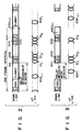
- central equipment unit 1 including a PBX, and a plurality of terminal equipment units 21, 22, ..., 2 n , each having concentration and distribution functions, are disposed at locations remote from one another.
- a bus-cofigured signal transmission line having up link 3 and down link 4 is extended from central equipment unit 1, and each terminal equipment unit is connected at a different position on the signal transmission line. Therefore, a signal transmission time between each terminal equipment unit and central equipment unit 1 depends on a position where the terminal equipment unit is connected to the signal transmission line.
- To each terminal equipment unit is connected at least one terminal device 5 such as a telephone set or a data processing device. The number of terminal devices 5 connected to a terminal equipment unit need not be constant.
- the terminal equipment units are assigned with numbers (addresses) #1, #2, ..., #i, ..., #n.
- Central equipment unit 1 transmits subframe data signals addressed to the respective terminal equipment units over down link 4 on a time-division multiplexing basis within one frame interval, and the respective terminal equipment units sequentially transmit subframe data signals to central equipment unit 1 over up link 3.
- the signal transmission line may be a frequency multiplex transmission line in which the up link and the down link are adapted for different transmission frequency bands, or two separate transmission lines may be used for signal transmission in the same transmission frequency band.
- one of the terminal equipment units is designated every frame interval, and the designated terminal equipment unit transmits a response signal to the central equipment unit.
- the central equipment unit measures a time (transmission delay time) between a reference timing in one frame interval and a receiving timing of the response signal transmitted from the terminal equipment unit, and transmits measured data to the terminal equipment unit, so that the terminal equipment unit adjusts a transmission start timing of a data signal (subframe signal) for the central equipment unit.
- FIG. 2 An example of a format of a frame signal transmitted from the central equipment unit to each terminal equipment unit over the down link is shown in Fig. 2.
- the format includes a field of a frame sync signal (FS) or a frame delimiter, a field of an assignment signal (ASGi) including address information for designating a terminal equipment unit having an address number i or an address field, a dummy data field, and a data field including subframe signals DO1, DO2, ..., DOn addressed to the respective terminal equipment units 21, 22,..., 2 n .
- an assignment signal (ASGi+1) for designating a terminal equipment unit having an address number i+1 is transmitted.
- the subframe signal is transmitted in a time slot (TS) assigned to the corresponding terminal equipment unit.
- TS time slot
- the frame signals may be continuously transmitted from the central equipment unit to the respective terminal equipment units via the down link.
- the FS field, the ASG field, and the dummy data field are adapted for a window for measuring the transmission delay times.
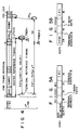
- response signal RSPi-1 is transmitted from the terminal equipment unit having address number i-1 and designated by signal ASGi-1 in the previous frame signal, and then subframe data signals DI1, DI2, ..., DIn are transmitted from the respective terminal equipment units. These subframe data signals are transmitted in time slots assigned to the respective terminal equipment units.
- a response signal, following signal RSPi-1, is RSPi transmitted from a terminal equipment unit having address number i and designated by signal ASGi.
- Signal RSPi-1 is only required to reach the central equipment unit within a delay measurement window of a frame signal carrying ASGi signal. A timing at which a response signal reaches the central equipment unit within the delay measurement window depends on the position of a terminal equipment unit transmitted the response signal.
- each terminal equipment unit measures a transmission delay time.
- a terminal equipment unit designated by signal ASGi transmitted from the central equipment unit transmits signal RSPi to the central equipment unit via the up link, and receives signal RSPi sent back from the central equipment unit via the down link.
- the delay measurement window adapted for transmitting and receiving signal RSPi is limited within an interval between the ASGi field and the data field, as shown in Fig. 3. Therefore, since a time interval which cannot be used for the delay measurement increases as compared with the system according to the present invention, it is difficult to increase time slots used for data signal tranmissions. As a result, the utility efficiency of the time slots is reduced.
- a transmission initiation timing of a frame signal is set to a reference timing of the central equipment unit.
- the frame signal reaches terminal equipment unit 2i, having address i , via the down link with a certain delay time.
- the terminal equipment unit generates a first TRANSMIT ENABLE signal TREN1 to transmit to RSP signal after a predetermined period TXTo of time, which substantially corresponds to a frame interval, from a reception start timing (reference timing of the terminal equipment unit) of the frame signal.
- the RSP signal is transmitted to the central equipment unit over the up link, and the central equipment unit measures a time difference ⁇ T ( ⁇ 0) between the next frame reference timing and a reception timing of the RSP signal.
- the terminal equipment unit generates a TRANSMIT ENABLE signal TREN2 after a delay of time TXT from the reference timing.
- the RSP signal is transmitted at the timing when signal TREN2 is generated, the RSP signal arrives at the central equipment unit at the reference timing of the next frame.
- the RSP signal need not be transmitted in response to signal TREN2, and a generation timing of signal TREN2 is utilized as a reference timing for the corresponding terminal equipment unit to transmit the subframe signal to the central equipment unit.
- Figs. 5A and 5B respectively show examples of formats of signal ASGi for requesting the terminal equipment unit 2i to transmit the response signal, and response signal RSPi transmitted from the terminal equipment unit 2i.
- signal ASGi includes an ASG delimiter (32 bits), address information I (i-1, 16 bits) of the terminal equipment unit 2i-1 which has already transmitted response signal RSPi-1, corrected transmission timing control information (TXT, 16 bits) for the terminal equipment unit 2i-1, address information II (i, 16 bits) of the terminal equipment unit 2i which is requested to transmit the response signal, and error detection signal CRC (16 bits).
- Signal RSPi includes a sync signal (24 bits), address information (i, 16 bits) representing a source of signal RSPi, transmission timing information (TXTo, 16 bits), and error detection signal CRC (16 bits).
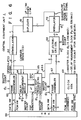
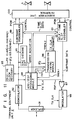
- Diplexer 61 which applies a received signal, transmitted from the terminal equipment units over up link 3, to demodulator 62.
- Demodulator 62 demodulates the received signal and forms a carrier sense signal CS.
- the demodulated signal is applied to frame disassembler 63, delay measurement module 64, and ASG/RSP processing module 65.
- Carrier sense signal CS is applied to frame disassembler 63 and delay measurement module 64.
- Frame disassembler 63 disassembles the subframe signal transmitted from a terminal equipment unit and included in the demodulated signal, and supplies audio PCM data and control data to PBX 66, respectively, through a PCM highway (HW) and a data highway (HW).
- PBX 66 performs exchange processing of data signals transmitted from the terminal equipment units, and supplies audio PCM data and control data to frame assembler 67, respectively, through PCM HW and data HW.
- PBX 66 supplies 2.048-MHz PCM clock signal PCM CLK and a PCM HW frame sync signal to clock generator 68 which generates master clock ⁇ 1 (4.096 MHz), delay measurement clock ⁇ 2 (65.536 MHz), and a sequencer master count outputs (0 to 7FFF H) synchronous with clock ⁇ 2.
- master clock ⁇ 1 4.096 MHz
- delay measurement clock ⁇ 2 (65.536 MHz)
- sequencer master count outputs (0 to 7FFF H) synchronous with clock ⁇ 2.
- Frame assembler 67 assembles PCM data (3 bits) and control data (1 bit), supplied from PBX 66 and addressed to one terminal equipment unit, into a subframe data signal for a time slot assigned to the terminal equipment unit, and sends the subframe data signal to selector/CRC generator 69.
- Selector 69 selects subframe signals generated by assembler 67 and ASG signal (including the frame sync signal and dummy data) generated by module 65 in accordance with the format of the frame signal shown in Fig. 2 for application to modulator 70.
- an output of selector 69 has 2 bits. This is because an output signal of selector 69 is subjected to quadrature phase shift keying in modulator 70.
- delay measurement module 64 In response to the demodulated data signal and carrier sense signal CS supplied from demodulator 62, delay measurement module 64 generates information ⁇ T which represents a time difference between the transmission start timing of the frame signal and the reception timing of the RSP signal, clock signal RSP CLK (4.096 MHz) recovered from the demodulated RSP signal, and an RSP nondetection signal which represents that the RSP signal could not be detected within a predetermined interval, these signals being applied to AGS/RSP processing module 65.
- Module 65 generates signal ASGi in the format consisting of fields from the ASG delimiter to terminal address II, as shown in Fig. 5A.
- the CRC signal is generated in generator 69 and added subsequent to the field of terminal address II of signal ASGi. As shown in Fig. 2, the CRC signal is generated based on signals existing from the dummy data field of one frame signal to the field of terminal address II in the ASG signal of the next frame signal.
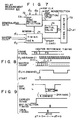
- delay measurement module 64 includes timing generator 71, RSP sync pattern detector 72, down counter 73, and register 74 into which an initial value of delay measurement information is preset.
- timing generator 71 supplies a delay measurement start signal (load instruction) to down counter 73 so that the initial value of register 74 is loaded into down counter 73.
- Timing generator 71 generates an RSP detection window signal at a timing when the RSP signal is likely to be received and supplies it to RSP sync pattern detector 72.
- Detector 72 is set ready for detecting RSP signal by the window signal, and responsive to carrier sense signal CS and the demodulated data signal supplied from demodulator 62 to detect the RSP signal.
- detector 72 supplies a count stop signal to counter 73.
- detector 72 recovers clock signal RSP CLK from the RSP signal, and generates the RSP nondetection signal when the RSP signal is not detected.
- down counter 73 In response to the start signal obtained from timing generator 71 which coincides with a transmission start timing of one frame signal in central equipment unit 1, down counter 73 starts a down count. In response to the stop signal obtained from RSP sync pattern detector 72 which coincides with the RSP signal detection timing, counter 73 stops the down count. The count of counter 73, obtained when the down count is stopped, represents a time difference ⁇ T between the transmission start timing (reference timing) of the frame signal and the RSP signal reception (detection) timing (Fig. 4).
- the reference timing of central equipment 1 i.e., the down count start timing of down counter 73 is set to the timing when the master count, indicating a count from 0 to 7FFF H , indicates 0, and the start signal for down counter 73 is generated at this timing.
- a frame signal transmission is started from the frame sync signal FS.
- RSP sync pattern detector 72 detects whether an output signal of demodulator 62 remains low during a period of eight clocks of delay measurement clock ⁇ 2 (4.098 MHz x 16) after carrier sense signal CS is applied. If this is detected, an RSP detection pulse is generated after a delay of 1/2 bit time from a transition of the sync pattern from a high level to a low level.
- ASG/RSP processing module 65 will be described below with reference to Fig. 10.
- Module 65 includes serial to parallel conversion shift register 81, central processing unit (CPU) 82, RAM/ROM 83 for storing data and CPU programs, parallel to serial conversion shift register 84, decoder 85, clock counter 86, interrupt controller (counter/timer controller) 87, and ASG output controller 88.
- Shift register 81 receives a demodulated signal from demodulator 62 in response to clock RSP CLK. More specifically, register 81 is adapted to receive the RSP signal sync field, the terminal address field, and the timing data field shown in Fig. 5B. Decoder 85 decodes "0" of the master count to reset counter 86. Counter 86 counts clock RSP CLK. When the desired data fields are loaded into register 81, counter 86 instructs controller 87 to cause CPU 82 to receive the data from register 81.
- CPU 82 assembles the ASG delimiter field, the terminal address field (#i-1), the timing data field (TXT), and the terminal address field (#i) as shown in Fig. 5A, following frame sync field FS.
- the terminal address field (#i) is adapted to poll the terminal equipment unit having address i for the purpose of measuring a transmission delay time.
- CPU 82 loads such assembled data into register 84. Controller 88 supplies the data loaded in register 84, in response to the master count "0", to selector/CRC generator 69 for transmission to the terminal equipment units.
- Diplexer 91 is connected to the signal transmission line and applies a frame signal transmitted from central equipment unit 1 to demodulator 92.
- a demodulated data signal is applied to receive clock recovery circuit 93 where 4.096-MHz receive clock ⁇ 1 ⁇ is recovered from the demodulated data signal and frequency-multiplied by a factor of 16 to generate 65.536-MHz transmission timing adjustment clock ⁇ 2 ⁇ .
- the demodulated data signal is also applied to ASG/RSP processing module 94 and CRC checking circuit 95.
- Module 94 detects polling address information II, addressed to itself and included in the ASG signal, so as to generate the RSP signal, and extracts timing adjustment information TXT addressed to itself from the ASG signal after the delay time measurement.
- CRC checking circuit 95 checks the CRC signal included in the ASG signal. If an error is detected, circuit 95 generates an error indication signal to disable ASG/RSP processing module 94.
- Transmission timing module 96 receives the demodulated data signal, transmission timing adjusting clock ⁇ 2 ⁇ , and transmission timing information TXT extracted by module 94 and generates transmission enable signals TREN1 and TREN2 shown in Fig. 4, and 4.096-MHz transmission clock TX CLK. In response to signal TREN1 and clock TX CLK, module 94 outputs the RSP signal for the delay time measurement after a delay of time TXTo from the detection timing of the frame signal. The RSP signal is supplied to modulator 98 through OR gate 97 and a modulated signal is applied to diplexer 91 for transmission to central equipment unit 1 over up link 3.
- the demodulated output signal of demodulator 92 is applied to subframe disassembler 99.
- disassembler 99 disassembles the subframe data addressed to itself from central equipment unit 1, and supplies audio PCM data and control data such as a ringing control signal for terminal device 5 to subscriber line interface 100.
- Interface 100 supplies audio PCM data and control data such as a hook/dial pulse generated by device 5 to self-time slot assembler 101.
- Assembler 101 is responsive to the time-slot data supplied from module 94, signal TREN2 supplied from module 96, and clock TX CLK to apply a subframe data signal, in a time slot assigned to itself, to modulator 98 through OR gate 97.
- the subframe data signal is modulated and applied to diplexer 91 for transmission over up link 3.
- Assembler 101 counts clocks TX CLK for a predetermined number corresponding to t ⁇ in response to signal TREN2, and outputs the subframe signal when counting the predetermined number of clocks TX CLK.
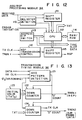
- Fig. 12 shows ASG/RSP processing module 94.
- Delimiter detector 110 detects an ASG delimiter signal from demodulated data signal supplied from demodulator 92. When the ASG delimiter signal is detected, detector 110 enables shift register 111 to receive address information I, timing information TXT, and address information II contained in the ASG signal. When the above information is loaded into register 111, detector 110 causes CPU 112 to receive the contents of register 111. To CPU 112 is applied the address information of the self terminal equipment unit provided by address dip switches 113. CPU 112 is programmed by ROM 114 and detects whether or not the address information supplied from register 111 is the self address. When address information I (#i-1) is the self address, CPU 112 supplies timing information TXT to module 96.
- RSP transmission controller 116 starts the transmission of the RSP signal stored in register 115 at the the generation timing of signal TREN1.
- Fig. 13 shows an arrangement of transmission timing module 96.
- a low level period of one bit time is present at a predetermined position of frame sync signal FS of the frame signal transmitted from central equipment unit 1.
- ASG pattern detector 121 detects the predetermined pattern of the frame sync signal in response to the demodulated data signal, clock RX CLK, and clock ⁇ 2 ⁇ . The detection timing of the predetermined pattern provides the reference timing of the terminal equipment unit.
- initial value TXTo preset in register 123 is loaded into down counter 122, and timing adjustment information TXT provided from module 94 is loaded into down counter 124.
- Counters 122 and 124 are counted down by transmission timing adjusting clock ⁇ 2 ⁇ . When counted down to 0, counter 122 generates RSP signal transmission enable signal TREN1. When counted down to 0, counter 124 generates subframe (time slot) data transmission enable signal TREN2.
- Counter 124 may be arranged to generate transmission clock TX CLK.
- the central equipment unit transmits the ASG signal to the terminal equipment units, and each terminal equipment unit transmits the RSP signal to the central equipment unit in response to the ASG signal addressed thereto. That is, unlike the prior invention described above, each terminal equipment unit is not required to receive a signal which has been transmitted by itself and then sent back from the central equipment unit as it is, but is only required to receive signals generated by the central equipment unit. Thus each terminal equipment unit can stably receive signals. Therefore, a demodulator may be simple in construction.
- the present invention is not limited to the above embodiment.
- the description has been made of the case wherein a predetermined time slot is fixedly assigned to a terminal equipment unit.
- the system of the present invention may be applied to a demand assign system in which each terminal equipment unit demands a time slot, and the central equipment unit assigns time slots to the terminal equipment units on demand.
- the demand assign system it is required that the RSP signal be transmitted in response to transmission enable signal TREN2 after the measurement of a delay time. By doing so, the RSP signal arrives at the central equipment unit at a predetermined timing of one frame interval. This increases the flexibility of a frame arrangement.
- the formats of the ASG and RSP signals are not limited to those shown in Figs. 5A and 5B.
- the ASG and RSP signals may include control information as needed.
- the control information may carry information of a time slot assigned to a terminal equipment unit on demand.
- the timing t ⁇ at which each terminal equipment unit transmits a subframe signal varies in accordance with the time slot information.
Landscapes
- Engineering & Computer Science (AREA)
- Computer Networks & Wireless Communication (AREA)
- Signal Processing (AREA)
- Time-Division Multiplex Systems (AREA)
- Small-Scale Networks (AREA)
Claims (10)
- Kommunikationsnetzwerksystem mit:
einer zentralen Ausrüstungseinheit (1);
einer Vielzahl von Terminal- bzw. Endgerätausrüstungseinheiten (2₁, 2₂,....., 2n), wobei an jede mindestens eine Endgerätvorrichtung (5) angeschlossen ist;
wobei die zentrale Ausrüstungseinheit (1) und die Endgerätausrüstungseinheiten 5 durch eine Aufwärtsverbindung (3) und eine Abwärtsverbindung (4) zur Übertragung von Informationsdaten zwischen der zentralen Ausrüstungseinheit (6) und den Endgerätausrüstungseinheiten (5) verbunden sind;
wobei die zentrale Ausrüstungseinheit (1) eine Einrichtung zur Bereitstellung von Bezugszeitsteuerungen bzw. -zeitpunkten und eine Einrichtung zum Übertragen eines Signals, das ein Adreßfeld aufweist, das eine der Endgerätausrüstungseinheiten (2₁, 2₂,....., 2n) bestimmt, auf der Abwärtsverbindung an eine Teilnehmerstation hat;
wobei jede der Endgerätausrüstungseinheiten (2₁, 2₂,....., 2n) eine Einrichtung zum Übertragen eines Antwortsignals auf der Aufwärtsverbindung an die zentrale Ausrüstungseinheit (68), wenn sie durch das Adreßfeld bestimmt ist, hat;
und wobei die zentrale Ausrüstungseinheit (1) eine Einrichtung zum Ermitteln einer Verzögerungszeit, die durch die Laufzeit der Signale zwischen der zentralen Ausrüstungseinheit (1) und der bestimmten Endgerätausrüstungseinheit (2₁, 2₂,....., 2n) verursacht ist, und eine Einrichtung zum Übertragen von Übertragungszeitsteuerungs- bzw. -zeitpunkt-Abgleichinformationen aufgrund der ermittelten Verzögerungszeit an die bestimmte Endgerätausrüstungseinheit hat, dadurch gekennzeichnet,
daß die Übertragungseinrichtung der zentralen Ausrüstungseinheit eine Einrichtung (65, 66, 67, 68, 69, 70) aufweist zum Übertragen, auf der Abwärtsverbindung, eines Rahmensignals, das aus einem Verzögerungsmeßfensterfeld und einem Datenfeld besteht, worin Unterrahmeninformationssignale (D01, D02, ...) auf einer Zeitteilungs-Multiplexbetriebsbasis auf der Abwärtsverbindung jedes Mal angeordnet sind, wenn das Bezugssignal ankommt, wobei das Verzögerungsmeßfensterfeld des Rahmensignals das Adreßfeld hat;
daß jede Übertragungseinheit der Endgerät Ausrüstungseinheiten eine Einrichtung (94, 96, 97, 98) aufweist zum Übertragen des Antwortsignals (RSP) auf der Aufwärtsverbindung nach einer Verzögerung von einem vorbestimmten Zeitintervall (TXTo) ab dem Empfangszeitpunkt des Rahmensignals, so daß das Antwortsignal bei der zentralen Ausrüstungseinheit innerhalb des Verzögerungsmeßfensterfelds des nächsten Rahmensignals ankommt, wobei das Antwortsignal Selbstadreßinformationen trägt;
daß die zentrale Ausrüstungseinheit ferner aufweist: eine Einrichtung (64) zum Messen einer Verzögerungszeit (Δ T) zwischen dem Bezugszeitpunkt zum Übertragen des nächsten Rahmensignals und dem Empfangszeitpunkt des Antwortsignals;
und eine Einrichtung (64) zum Übertragen von Übertragungszeitpunkt-Abgleichinformationen (TXT) aufgrund der gemessenen Verzögerungszeit und Adreßinformationen der Endgerätausrüstungseinheit, die das Antwortsignal übertragen hat, im Adreßfeld des nächsten Rahmensignals; und
daß jede der Endgerätausrüstungseinheiten ferner eine Einrichtung (101) aufweist zum Übertragen eines Unterrahmensignals (DI) nach einem Zeitintervall (TXT + tα), das von den Übertragungszeitpunkt-Abgleichinformationen abhängt, ab dem Empfangszeitpunkt eines Rahmensignals,
wobei die Übertragungsabgleichinformationen für eine Endgerätausrüstungseinheit ermittelt werden können, während Dateninformationen zwischen der jeweiligen Endgerätausrüstungseinheit und der zentralen Ausrüstungseinheit übertragen werden. - Netzwerk nach Anspruch 1, dadurch gekennzeichnet, daß die zentrale Ausrüstungseinheit die Rahmensignale kontinuierlich überträgt.
- Netzwerk nach Anspruch 1, dadurch gekennzeichnet, daß das Verzögerungsmeßfensterfeld ein Rahmensynchronsignalfeld, ein Adreßfeld und ein Blinddatenfeld hat.
- Netzwerk nach Anspruch 1, dadurch gekennzeichnet, daß das Adreßfeld des Rahmensignals erste Adreßinformationen zum Bestimmen einer der Endgerätausrüstungseinheiten zum Messen der Verzögerungszeit, zweite Adreßinformationen, die eine Adresse einer Endgerätausrüstungseinheit darstellen, die der Verzögerungszeitmessung unterzogen wurde, und ÜbertragungszeitpunktAbgleichinformationen auf der Grundlage eines Ergebnisses der Verzögerungszeitmessung der Endgerätausrüstungseinheit trägt.
- Netzwerk nach Anspruch 1, dadurch gekennzeichnet, daß das Antwortsignal Informationen, die auf eine Zeit ab dem Empfangszeitpunkt eines Rahmensignals bis zum Übertragungzeitpunkt des Antwortsignals hinweisen, sowie Selbstadreßinformationen trägt.
- In einem Kommunikationsnetzwerk mit: einer zentralen Ausrüstungseinheit (1); einer Vielzahl von Endgerätausrüstungseinheiten (2₁ bis 2n), wobei jede der Endgerätausrüstungseinheiten mindestens eine Endgerätvorrichtung (5) hat, die daran angeschlossen ist; und einer Signalübertragungsleitung, die zwischen der zentralen Ausrüstungseinheit und den Endgerätausrüstungseinheiten verbunden ist, wobei die Signalübertragungsleitung eine Aufwärtsverbindung (3) und eine Abwärtsverbindung (4) zur Übertragung von Informationsdaten zwischen der zentralen Ausrüstungseinheit (1) und den Endgerätausrüstungseinheiten (5) hat; wobei die zentrale Ausrüstungseinheit Unterrahmensignale (D01 bis D0n) an die Endgerätausrüstungseinheiten über die Abwärtsverbindung auf einer Zeitteilungs-Multiplexbetriebsbasis innerhalb eines Rahmenintervalls überträgt, und wobei die Endgerätausrüstungseinheiten Unterrahmensignale (DI1 bis DIn) an die zentrale Ausrüstungseinheit über die Aufwärtsverbindung übertragen,
ein Verfahren zum Zeitsteuerungs- bzw. Zeitpunktabgleich der Signalübertragung der Endgerätausrüstungseinheiten zum Verhindern einer Kollision von Unterrahmensignalen, die von den Endgerätausrüstungseinheiten auf der Aufwärtsverbindung übertragen werden, wobei das Verfahren die Schritte umfaßt zum:
periodischen Erzeugen von Bezugszeitpunkten in der zentralen Ausrüstungseinheit (1);
Übertragen eines Rahmensignals von der zentralen Ausrüstungseinheit (1) an die Endgerätausrüstungseinheiten (2₁ bis 2n) über die Abwärtsverbindung (3) als Reaktion auf jeden der Bezugszeitpunkte, wobei das Rahmensignal aus einem Verzögerungsmeßfensterfeld und einem Datenfeld besteht, worin die Unterrahmensignale (DO1 bis DOn), die an die Endgerätausrüstungseinheiten adressiert sind, auf einer Zeitteilungs-Multiplexbetriebsbasis angeordnet sind, und wobei das Verzögerungsmeßfensterfeld ein Adreßfeld hat, das Adreßinformationen trägt, die eine der Endgerätausrüstungseinheiten zur Verzögerungszeitmessung bestimmen;
Übertragen eines Antwortsignals (RSPi) von der bestimmten Endgerätausrüstungseinheit (2₁ bis 2n) auf der Aufwärtsverbindung (4) nach einer Verzögerung von einem vorbestimmten Zeitintervall ab dem Empfangszeitpunkt des jeweiligen Rahmensignals, das von der zentralen Ausrüstungseinheit übertragen wird, so daß das Antwortsignal bei dieser zentralen Ausrüstungseinheit innerhalb eines Verzögerungsmeßfensterfelds des nächsten Rahmensignals ankommt, wobei das Antwortsignal Selbstadreßinformationen trägt;
Messen, in der zentralen Ausrüstungseinheit (4), einer Verzögerungszeit (Δ T) zwischen dem Bezugszeitpunkt für die Übertragung des nächsten Rahmensignals und dem Empfangszeitpunkt des von der Endgerätausrüstungseinheit übertragenen Antwortsignals;
Übertragen von Übertragungszeitpunkt-Abgleichinformationen (TXT) von der zentralen Ausrüstungseinheit (1) an eine Endgerätausrüstungseinheit, die das Antwortsignal übertragen hat, aufgrund der gemessenen Verzögerungszeit (Δ T) und von Adreßinformationen der Endgerätausrüstungseinheit, die das Antwortsignal übertragen hat, im Adreßfeld des nächsten Rahmensignals; und
Übertragen eines Unterrahmensignals (DI) von jeder der Endgerätausrüstungseinheiten auf der Aufwärtsverbindung (3) nach einer Verzögerung eines Zeitintervalls (TXT + tα) in Abhängigkeit von den Übertragungszeitpunkt-Abgleichinformationen (TXT), die von der zentralen Ausrüstungseinheit übertragen werden, ab dem Empfangszeitpunkt des Rahmensignals,
wodurch die Übertragungszeitpunkt-Abgleichinformationen für eine Endgerätausrüstungseinheit ermittelt werden können, während Dateninformationen zwischen der jeweiligen Endgerätausrüstungseinheit und der zentralen Ausrüstungseinheit übertragen werden. - Verfahren nach Anspruch 6, dadurch gekennzeichnet, daß die Rahmensignale kontinuierlich über die Abwärtsverbindung von der zentralen Ausrüstungseinheit an die Endgerätausrüstungseinheiten übertragen werden.
- Verfahren nach Anspruch 6, dadurch gekennzeichnet, daß das Verzögerungsmeßfensterfeld ein Rahmensynchronsignalfeld, ein Adreßfeld und ein Blinddatenfeld hat.
- Verfahren nach Anspruch 6, dadurch gekennzeichnet, daß das Adreßfeld des Rahmensignals erste Adreßinformationen zum Bestimmen einer der Endgerätausrüstungseinheiten zum Messen der Verzögerungszeit, zweite Adreßinformationen, die eine Adresse der Endgerätausrüstungseinheit, die der Verzögerungszeitmessung unterzogen wurde, darstellen, und Übertragungszeitpunkt-Abgleichinformationen aufgrund eines Ergebnisses der Verzögerungszeitmessung der Endgerätausrüstungseinheit trägt.
- Verfahren nach Anspruch 6, dadurch gekennzeichnet, daß das Antwortsignal Informationen, die auf eine Zeit ab dem Empfangszeitpunkt eines Rahmensignals bis zum Übertragungszeitpunkt des Antwortsignals hinweisen, sowie Selbstadreßinformationen trägt.
Applications Claiming Priority (2)
| Application Number | Priority Date | Filing Date | Title |
|---|---|---|---|
| JP85524/86 | 1986-04-14 | ||
| JP61085524A JPH06101737B2 (ja) | 1986-04-14 | 1986-04-14 | 集線分配方式 |
Publications (3)
| Publication Number | Publication Date |
|---|---|
| EP0242142A2 EP0242142A2 (de) | 1987-10-21 |
| EP0242142A3 EP0242142A3 (en) | 1989-08-23 |
| EP0242142B1 true EP0242142B1 (de) | 1993-12-29 |
Family
ID=13861289
Family Applications (1)
| Application Number | Title | Priority Date | Filing Date |
|---|---|---|---|
| EP87303164A Expired - Lifetime EP0242142B1 (de) | 1986-04-14 | 1987-04-10 | System zum Zeitsteuerungsabgleich der Signalübertragung zur Vermeidung von Kollisionen |
Country Status (5)
| Country | Link |
|---|---|
| US (1) | US4811338A (de) |
| EP (1) | EP0242142B1 (de) |
| JP (1) | JPH06101737B2 (de) |
| CA (1) | CA1268869A (de) |
| DE (1) | DE3788587T2 (de) |
Families Citing this family (31)
| Publication number | Priority date | Publication date | Assignee | Title |
|---|---|---|---|---|
| US5487066A (en) * | 1988-03-21 | 1996-01-23 | First Pacific Networks, Inc. | Distributed intelligence network using time and frequency multiplexing |
| US4845735A (en) * | 1988-06-14 | 1989-07-04 | General Datacomm, Inc. | Non-interfering method for measuring propagation delay of telecommunications network and apparatus for accomplishing same |
| FI894021A7 (fi) * | 1988-08-31 | 1990-03-01 | Fujitsu Ltd | Neuronstruktur. |
| FR2636482B1 (fr) * | 1988-09-13 | 1993-11-12 | Abiven Jacques | Procede de synchronisation pour le multiplexage de mots dans un reseau de communication etoile a fibres optiques |
| US5034944A (en) * | 1988-10-31 | 1991-07-23 | At&T Bell Laboratories | Optical fiber bus controller |
| WO1990013956A1 (en) * | 1989-04-28 | 1990-11-15 | First Pacific Networks, Inc. | Distributed intelligence network using time and frequency multiplexing |
| AU639665B2 (en) * | 1989-04-28 | 1993-08-05 | Technologies Futures, Inc. d/b/a Orion Group, Inc. | Distributed intelligence network |
| DE4001153A1 (de) * | 1990-01-17 | 1991-07-18 | Schulte Schlagbaum Ag | Magnetkartenschloss mit schluesselkarte |
| US5130983A (en) * | 1990-03-27 | 1992-07-14 | Heffner Iii Horace W | Method of polling to determine service needs and the like |
| JPH0779347B2 (ja) * | 1990-09-13 | 1995-08-23 | 株式会社シーエーティブイ基盤技術研究所 | 時分割多重通信方式 |
| NL9002401A (nl) * | 1990-11-05 | 1992-06-01 | Philips Nv | Kommunikatiesysteem en een centrale besturingseenheid en een kommunikatiepost in het kommunikatiesysteem. |
| US6847611B1 (en) | 1990-12-10 | 2005-01-25 | At&T Corp. | Traffic management for frame relay switched data service |
| DE69218913T2 (de) * | 1992-01-31 | 1997-07-17 | Cit Alcatel | Verfahren zur Bestimmung der Laufzeit zwischen einer entfernten Endstation und einer zentralen Endstation, in einem bidirektionalen Punkt-zu-Mehrpunkt-Übertragungssystem |
| ZA931077B (en) * | 1992-03-05 | 1994-01-04 | Qualcomm Inc | Apparatus and method for reducing message collision between mobile stations simultaneously accessing a base station in a cdma cellular communications system |
| US5335226A (en) * | 1992-06-18 | 1994-08-02 | Digital Equipment Corporation | Communications system with reliable collision detection method and apparatus |
| US6771617B1 (en) * | 1993-06-17 | 2004-08-03 | Gilat Satellite Networks, Ltd. | Frame relay protocol-based multiplex switching scheme for satellite mesh network |
| US5434850A (en) | 1993-06-17 | 1995-07-18 | Skydata Corporation | Frame relay protocol-based multiplex switching scheme for satellite |
| US5710755A (en) * | 1993-11-15 | 1998-01-20 | Pitney Bowes | Communication system for control applications |
| DE4417771A1 (de) * | 1994-05-20 | 1995-11-23 | Siemens Ag | Optisches TDM/TDMA-System mit erhöhtem Reichweitenbereich |
| DE19504488C1 (de) * | 1995-02-10 | 1996-06-20 | Siemens Ag | Verfahren zur Initialisierung von peripheren Einrichtungen durch eine programmgesteuerte Zentraleinrichttung eines Kommunikationssystems |
| US5802061A (en) * | 1995-10-19 | 1998-09-01 | Cabletron Systems, Inc. | Method and apparatus for network access control with implicit ranging and dynamically assigned time slots |
| US5793772A (en) * | 1995-11-29 | 1998-08-11 | Motorola, Inc. | Method and apparatus for synchronizing timing of components of a telecommunication system |
| JP3442228B2 (ja) * | 1996-08-29 | 2003-09-02 | 松下電器産業株式会社 | 同期保持装置 |
| US6081524A (en) | 1997-07-03 | 2000-06-27 | At&T Corp. | Frame relay switched data service |
| US6567420B1 (en) * | 1999-04-15 | 2003-05-20 | Qualcomm, Incorporated | Method and apparatus for high rate channel access control |
| TW527796B (en) * | 2001-08-30 | 2003-04-11 | Tailyn Comm Co Ltd | ATM communication system for improving UTOPIA communication interface and method therefor |
| TWI307228B (en) * | 2002-03-25 | 2009-03-01 | Asulab Sa | A method of transmitting information between two units each provided with means for sending and/or receiving signals |
| US7668092B2 (en) * | 2002-11-21 | 2010-02-23 | Honeywell International Inc. | Data transmission system and method |
| CN102075820B (zh) * | 2009-11-23 | 2015-05-20 | 中兴通讯股份有限公司 | 在无源光网络中测距的方法和装置 |
| EP3761570B1 (de) * | 2019-07-02 | 2024-05-08 | Nxp B.V. | Kollisionsdetektion auf einem can-bus |
| US11392520B1 (en) * | 2021-02-03 | 2022-07-19 | Cirrus Logic, Inc. | Timing adjustment to unused unit-interval on shared data bus |
Family Cites Families (8)
| Publication number | Priority date | Publication date | Assignee | Title |
|---|---|---|---|---|
| CA1158739A (en) * | 1980-04-30 | 1983-12-13 | William Rodman | Distributed network synchronization system |
| JPS58154947A (ja) * | 1982-03-10 | 1983-09-14 | Nec Corp | 時分割多元接続による無線回線の時間軸調整方式 |
| JPS59178894A (ja) * | 1983-03-30 | 1984-10-11 | Toshiba Corp | 集線分配方式 |
| DE3464185D1 (en) * | 1983-03-31 | 1987-07-16 | Toshiba Kk | Bus-configured local area network with data exchange capability |
| JPS59181797A (ja) * | 1983-03-31 | 1984-10-16 | Toshiba Corp | 集線分配方式 |
| JPS6124338A (ja) * | 1984-07-12 | 1986-02-03 | Nec Corp | 多方向多重通信方式 |
| JPS61145995A (ja) * | 1984-12-20 | 1986-07-03 | Toshiba Corp | 集線分配装置 |
| JPH0761183B2 (ja) * | 1986-01-09 | 1995-06-28 | 株式会社東芝 | 集線分配装置 |
-
1986
- 1986-04-14 JP JP61085524A patent/JPH06101737B2/ja not_active Expired - Fee Related
-
1987
- 1987-04-10 DE DE87303164T patent/DE3788587T2/de not_active Expired - Lifetime
- 1987-04-10 EP EP87303164A patent/EP0242142B1/de not_active Expired - Lifetime
- 1987-04-10 CA CA000534454A patent/CA1268869A/en not_active Expired
-
1988
- 1988-06-02 US US07/205,033 patent/US4811338A/en not_active Expired - Lifetime
Also Published As
| Publication number | Publication date |
|---|---|
| JPH06101737B2 (ja) | 1994-12-12 |
| US4811338A (en) | 1989-03-07 |
| EP0242142A2 (de) | 1987-10-21 |
| CA1268869A (en) | 1990-05-08 |
| EP0242142A3 (en) | 1989-08-23 |
| JPS62241451A (ja) | 1987-10-22 |
| DE3788587T2 (de) | 1994-04-28 |
| DE3788587D1 (de) | 1994-02-10 |
Similar Documents
| Publication | Publication Date | Title |
|---|---|---|
| EP0242142B1 (de) | System zum Zeitsteuerungsabgleich der Signalübertragung zur Vermeidung von Kollisionen | |
| US4694453A (en) | System for adjusting signal transmission timing in time-division multiplexing signal transmission | |
| EP0229684B1 (de) | Datenrahmensynchronisierungssystem für Zeitmultiplex-Übertragung | |
| KR960015848B1 (ko) | 시뮬캐스트 스케쥴러 | |
| US4513416A (en) | System for adjusting a time axis by using a control and an adjustment time slot in a satellite station of a TDMA network | |
| JP3907704B2 (ja) | ディジタルワイヤレス通信システム及びワイヤレス無線局 | |
| WO1995001022A1 (en) | Arrangement for defining a transmission delay in a subscriber network | |
| GB2277232A (en) | Timing of transmission from a mobile unit in a TDMA communications system | |
| EP0515029B1 (de) | Zeit-Multiplexkommunikationssystem | |
| CA2188076C (en) | Synchronization of wireless base stations by a service circuit in a telecommunication switching system | |
| JP3029343B2 (ja) | 移動通信における基地局間tdmaフレーム同期方式 | |
| JPS61144935A (ja) | デジタル式無線通信系の時間チヤンネル間の保護時間を短縮する方法および回路装置 | |
| US4688217A (en) | Method of implementing burst acquisition control in TDMA system | |
| RU96117584A (ru) | Способ синхронизации пакетов данных | |
| US7028093B2 (en) | Method of transferring user data packets | |
| JP3323809B2 (ja) | 時分割多重無線通信方式の受信電界強度測定装置 | |
| US7319686B1 (en) | Frame synchronization in multi-cell systems with a data interface | |
| CN1091564A (zh) | 具有多个发射台的无线寻呼系统 | |
| KR100219876B1 (ko) | 페이징 시스템의 동기식 호데이타 송출장치 | |
| JPH02276322A (ja) | 局間自動位相補償方式 | |
| JP2643832B2 (ja) | 伝播遅延量測定方式 | |
| JP2590809B2 (ja) | チヤンネル接続装置 | |
| JP2841909B2 (ja) | 移動体衛星通信システムの受信タイミング情報転送方法及び転送方式 | |
| JPS6269735A (ja) | 時分割多元接続通信システムにおけるバ−スト同期方式 | |
| JPH05347624A (ja) | 回線装置間通信路形成方式 |
Legal Events
| Date | Code | Title | Description |
|---|---|---|---|
| PUAI | Public reference made under article 153(3) epc to a published international application that has entered the european phase |
Free format text: ORIGINAL CODE: 0009012 |
|
| AK | Designated contracting states |
Kind code of ref document: A2 Designated state(s): DE FR GB |
|
| 17P | Request for examination filed |
Effective date: 19880211 |
|
| PUAL | Search report despatched |
Free format text: ORIGINAL CODE: 0009013 |
|
| AK | Designated contracting states |
Kind code of ref document: A3 Designated state(s): DE FR GB |
|
| 17Q | First examination report despatched |
Effective date: 19910819 |
|
| GRAA | (expected) grant |
Free format text: ORIGINAL CODE: 0009210 |
|
| AK | Designated contracting states |
Kind code of ref document: B1 Designated state(s): DE FR GB |
|
| REF | Corresponds to: |
Ref document number: 3788587 Country of ref document: DE Date of ref document: 19940210 |
|
| ET | Fr: translation filed | ||
| PLBE | No opposition filed within time limit |
Free format text: ORIGINAL CODE: 0009261 |
|
| STAA | Information on the status of an ep patent application or granted ep patent |
Free format text: STATUS: NO OPPOSITION FILED WITHIN TIME LIMIT |
|
| 26N | No opposition filed | ||
| REG | Reference to a national code |
Ref country code: GB Ref legal event code: 746 Effective date: 19981010 |
|
| REG | Reference to a national code |
Ref country code: FR Ref legal event code: D6 |
|
| REG | Reference to a national code |
Ref country code: GB Ref legal event code: IF02 |
|
| PGFP | Annual fee paid to national office [announced via postgrant information from national office to epo] |
Ref country code: GB Payment date: 20060405 Year of fee payment: 20 |
|
| PGFP | Annual fee paid to national office [announced via postgrant information from national office to epo] |
Ref country code: DE Payment date: 20060406 Year of fee payment: 20 |
|
| PGFP | Annual fee paid to national office [announced via postgrant information from national office to epo] |
Ref country code: FR Payment date: 20060410 Year of fee payment: 20 |
|
| REG | Reference to a national code |
Ref country code: GB Ref legal event code: PE20 |
|
| PG25 | Lapsed in a contracting state [announced via postgrant information from national office to epo] |
Ref country code: GB Free format text: LAPSE BECAUSE OF EXPIRATION OF PROTECTION Effective date: 20070409 |