EP0241708B1 - Douille d'ancrage à injection à insérer dans des trous préforés - Google Patents
Douille d'ancrage à injection à insérer dans des trous préforés Download PDFInfo
- Publication number
- EP0241708B1 EP0241708B1 EP87103494A EP87103494A EP0241708B1 EP 0241708 B1 EP0241708 B1 EP 0241708B1 EP 87103494 A EP87103494 A EP 87103494A EP 87103494 A EP87103494 A EP 87103494A EP 0241708 B1 EP0241708 B1 EP 0241708B1
- Authority
- EP
- European Patent Office
- Prior art keywords
- pipe
- injection
- injection anchor
- tube
- anchor
- Prior art date
- Legal status (The legal status is an assumption and is not a legal conclusion. Google has not performed a legal analysis and makes no representation as to the accuracy of the status listed.)
- Expired - Lifetime
Links
- 238000002347 injection Methods 0.000 title claims abstract description 75
- 239000007924 injection Substances 0.000 title claims abstract description 75
- 238000003780 insertion Methods 0.000 claims description 3
- 230000037431 insertion Effects 0.000 claims description 3
- 238000007373 indentation Methods 0.000 abstract description 13
- 238000004519 manufacturing process Methods 0.000 abstract description 5
- 150000001875 compounds Chemical class 0.000 description 12
- 244000089486 Phragmites australis subsp australis Species 0.000 description 2
- 238000013461 design Methods 0.000 description 2
- 239000004744 fabric Substances 0.000 description 2
- 239000000243 solution Substances 0.000 description 2
- 229910000831 Steel Inorganic materials 0.000 description 1
- 239000000853 adhesive Substances 0.000 description 1
- 230000001070 adhesive effect Effects 0.000 description 1
- 238000010276 construction Methods 0.000 description 1
- 238000011161 development Methods 0.000 description 1
- 238000001746 injection moulding Methods 0.000 description 1
- 239000000463 material Substances 0.000 description 1
- 239000012778 molding material Substances 0.000 description 1
- 239000011470 perforated brick Substances 0.000 description 1
- 238000003825 pressing Methods 0.000 description 1
- 238000010992 reflux Methods 0.000 description 1
- 230000002787 reinforcement Effects 0.000 description 1
- 230000003014 reinforcing effect Effects 0.000 description 1
- 239000011343 solid material Substances 0.000 description 1
- 239000010959 steel Substances 0.000 description 1
- 238000010998 test method Methods 0.000 description 1
- 238000012360 testing method Methods 0.000 description 1
- 239000004753 textile Substances 0.000 description 1
- 238000004804 winding Methods 0.000 description 1
Images


Classifications
-
- F—MECHANICAL ENGINEERING; LIGHTING; HEATING; WEAPONS; BLASTING
- F16—ENGINEERING ELEMENTS AND UNITS; GENERAL MEASURES FOR PRODUCING AND MAINTAINING EFFECTIVE FUNCTIONING OF MACHINES OR INSTALLATIONS; THERMAL INSULATION IN GENERAL
- F16B—DEVICES FOR FASTENING OR SECURING CONSTRUCTIONAL ELEMENTS OR MACHINE PARTS TOGETHER, e.g. NAILS, BOLTS, CIRCLIPS, CLAMPS, CLIPS OR WEDGES; JOINTS OR JOINTING
- F16B13/00—Dowels or other devices fastened in walls or the like by inserting them in holes made therein for that purpose
- F16B13/14—Non-metallic plugs or sleeves; Use of liquid, loose solid or kneadable material therefor
- F16B13/141—Fixing plugs in holes by the use of settable material
- F16B13/146—Fixing plugs in holes by the use of settable material with a bag-shaped envelope or a tubular sleeve closed at one end, e.g. with a sieve-like sleeve, or with an expandable sheath
-
- E—FIXED CONSTRUCTIONS
- E04—BUILDING
- E04G—SCAFFOLDING; FORMS; SHUTTERING; BUILDING IMPLEMENTS OR AIDS, OR THEIR USE; HANDLING BUILDING MATERIALS ON THE SITE; REPAIRING, BREAKING-UP OR OTHER WORK ON EXISTING BUILDINGS
- E04G23/00—Working measures on existing buildings
- E04G23/02—Repairing, e.g. filling cracks; Restoring; Altering; Enlarging
- E04G23/0203—Arrangements for filling cracks or cavities in building constructions
- E04G23/0211—Arrangements for filling cracks or cavities in building constructions using injection
-
- E—FIXED CONSTRUCTIONS
- E04—BUILDING
- E04G—SCAFFOLDING; FORMS; SHUTTERING; BUILDING IMPLEMENTS OR AIDS, OR THEIR USE; HANDLING BUILDING MATERIALS ON THE SITE; REPAIRING, BREAKING-UP OR OTHER WORK ON EXISTING BUILDINGS
- E04G23/00—Working measures on existing buildings
- E04G23/02—Repairing, e.g. filling cracks; Restoring; Altering; Enlarging
- E04G23/0218—Increasing or restoring the load-bearing capacity of building construction elements
- E04G23/0222—Replacing or adding wall ties
Definitions
- the invention relates to an injection anchor to be inserted into predrilled holes, which consists of a tube which is closed at the rear end, which is provided with at least one radial outlet hole for the injection compound, and an elastic jacket which surrounds the tube.
- an injection anchor which has a smooth-walled tube, which is provided with round or slot-like outlet holes for the injection compound, with a reinforcing wire being wound around the tube, the wire enclosing and connected to the tube Rings is fixed in position.
- the pipe there or its reinforcement winding has an elastic jacket which, for example in the case of hollow blocks or perforated bricks, is to prevent injection molding material from creeping into cavities in an uncontrolled manner.
- the well-known injection anchor is due to its multi-part construction relatively expensive to manufacture and cumbersome to use. The outer casing can slip when inserted into a borehole, so that it loses its shut-off function in relation to cavities on the masonry side. In addition, the pull-out strength of the smooth-walled tube from the injection plug is very limited.
- Injection anchors are also known which consist of a solid material rod, which either have a drilled injection channel or injection tubes running outside along the anchor rod. These known embodiments are also relatively expensive to manufacture.
- the invention has for its object to provide an injection anchor that is inexpensive to manufacture as a mass article, that is easy to use and that has a high pull-out strength, both with regard to the entire injection plug from the predrilled bore and with regard to the pulling out of the tube from the Injection plug out.
- the solution to this problem is achieved according to the invention in that the tube is provided with diametrically opposed, rounded indentations over its length and, with the exception of its round end sections, alternating flat-oval cross-sectional areas and approximately round or almost round Has cross-sectional areas and that the elastic jacket is designed as a tube extending over the entire length of the tube, the ends of which are inserted into the tube ends and clamped to the tube by means of rivet-type fastening means.
- Such an injection anchor is made up of only a few parts, with lengths of commercially available tubes cut to length for the tube and tube lengths cut to length for the elastic jacket can be used, the jacket advantageously consisting of textile fabric or knitted fabric which can be radially expanded to a certain extent.
- the tube and the jacket are securely connected to one another using simple, rivet-like fastening means, so that the jacket cannot slip when inserted into a borehole.
- the jacket bulges into cavities, so that the injection plug formed is also held in a form-fitting manner in the masonry or the like. Due to its many indentations, the tube also sits positively in the injection plug that forms inside and outside the tube, so that the tube itself has a high pull-out strength. The tube undergoes a material pre-stretching due to the indentations, so that the corrugated tube does not deform back even under high tensile loads.
- the injection anchor can thus be a cheap mass article in lengths of up to several meters and with diameters of several centimeters, for. B. five centimeters, and it is foolproof in its handling.
- the tube is narrowed to about half the diameter in the area of the opposing indentations and that the tube is continuous, i. H. avoiding sharp edges. This shape avoids local peak loads when tensile or compressive forces are exerted on the anchor, so that the risk of the pipe or the injection plug being broken is prevented.
- the same rivet-like fasteners are used at both ends, which have a passage channel, with a closure piece being pressed into the rear fastener, which thus further improves the clamping of the tube end in the tube.
- the hose that is slipped in can have an end section protruding into the tube via the shaft of the fastening means, which end section acts as a check valve when the sprayer is set down and prevents the injection compound from escaping.
- the tube is provided near the rear end with a larger outlet hole and distributed over its length with comparatively smaller outlet holes.
- a positioning disk adapted to the borehole diameter is clamped between the rivet head of the fastening means and the pipe ends. This positioning disc ensures a coaxial alignment of the injection anchor with the borehole.
- the injection anchor can also be assigned connecting bolts which can be inserted into the tube and whose front part has a non-smooth surface, e.g. has an external thread.
- These connecting bolts are inserted into the tube before the injection compound has completely hardened, and the protruding end of the connecting bolt can, depending on its design, be used as a hook, eye, etc. for fastening or suspending further components.
- the tube is crimped at its front end, that the fastener is inserted into the tube with a high clamping force and that its shaft is provided with an internally threaded bore.
- the tensile force with which the fastener can be pulled off the pipe using a suitable tool is chosen to be equal to or slightly greater than the required minimum pull-out strength of the injection anchor. It is therefore possible to test the inserted anchors for their pull-out strength by pulling the front fastener off the pipe. In this way, you can check non-destructively whether the injection anchors have the required pull-out strength.
- the invention provides as an alternative solution that the tube is provided with diametrically opposed, rounded indentations at least over a large part of its length and, with the exception of its round end sections, alternately flat-oval cross-sectional areas and round or almost has round cross-sectional areas, and that the jacket is designed as a longitudinally elastic hose or stocking, which is attached on the one hand to the insertion end of the tube and on the other hand is attached to a flange ring which is slidably mounted on a front, round portion of the tube.
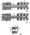
- the injection anchor shown in FIGS. 1 to 5 consists of a tube 1 and an elastic jacket 2 extending over the entire length of the tube, the ends 3, 4 of which are turned into the tube ends and are clamped to the tube by means of rivet-type fastening elements 5, 6 .
- the rivet-type fastening means each have a through channel 7, and a closure piece 8 is pressed tightly into the through channel of the rear fastening means.
- the tube 1 is, for example, a steel tube with a diameter of 10 millimeters and a wall thickness of 1 millimeter.
- the tube 1 is provided with opposing, rounded indentations 9, 10 over its length at regular intervals and, with the exception of its round end sections 11, 12, alternately each has a flat-oval cross-sectional area 14 according to the cross-sectional view according to FIG. 4 and approximately round or almost-round cross-sectional area 15 according to the cross-sectional view according to FIG. 5.
- the tube is narrowed to about half the tube diameter D.
- the indentations are made in such a way that the tube is continuously corrugated.
- the tube is provided with a larger radial outlet hole 16, and several comparatively smaller outlet holes 17 are distributed along its length.
- FIG. 6 illustrates an application example of the injection anchor according to FIGS. 1 to 5.
- Injection mass has been pressed through the through-channel of the front rivet-like fastening means 5, which initially fills the interior of the tube 1, then radially outwards through the outlet bore 16 and, if necessary, through the outlet bores 17 and spreads the elastic jacket 2 on the one hand until it abuts the borehole wall and on the other hand causes the elastic jacket 2 to bulge into cavities.
- injection compounds that set relatively quickly are usually used, so that there is no greater reflux pressure after the sprayer has been set down.
- a positioning disk 22, 23 is clamped between the rivet head of the fastening means 5, 6 and the ends of the tube 1, which is adapted approximately to the diameter of the borehole 20 and ensure a coaxial alignment of the tube 1.
- a connecting bolt 24 which is inserted or screwed into the tube 1 from the front and which has a non-smooth surface, e.g. carries an external thread 25 and the end protruding from the tube 1 can, depending on the design, be used as a hook, eyelet, threaded rod, etc. for attaching further elements.
- the tube 26 is provided with a crimped edge 27 at its front end and a rivet-like fastening element 29 is provided for clamping the inserted hose 28, the shaft of which has a widening 30 inwards of the flange 27 and with high clamping pressure into it Tube 26 is pressed.
- the through-channel of the fastening element 29 is here with an internal thread 31 provided, into which a pull-out tool can be screwed. If the injection anchor according to FIG. 8 is inserted into a borehole, its pull-out strength is checked after the hardening time in that such a pull is exerted on the fastening element 29 by means of the pull-out tool that it is pulled off the tube 26.
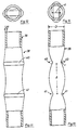
- FIG. 9 and 10 show an alternative embodiment of an injection anchor 32, the tube 33 of which is provided with indentations 34 oriented parallel to one another only in its rear region, which is inserted into a borehole, and that the front has an almost equally long, round section 35.
- the tube is surrounded by an elastic hose 36, which is tightly attached, for example glued or clamped, to the rear end 37 of the tube.
- the hose 36 is fastened tightly to an annular flange 38, which is mounted in a longitudinally displaceable manner on the front, round section 35 of the tube.
- the tube 36 is not only radially but also longitudinally elastic and is inherently shorter than the tube 33, as can be seen in FIG. 9.
- FIG. 9 shows an alternative embodiment of an injection anchor 32, the tube 33 of which is provided with indentations 34 oriented parallel to one another only in its rear region, which is inserted into a borehole, and that the front has an almost equally long, round section 35.
- the tube is surrounded by an elastic hose 36
- FIG. 10 shows the same injection anchor as in FIG. 9, but here the injection anchor is completely inserted into a correspondingly deeper borehole, the longitudinally elastic hose 36 having been extended to the length of the tube 33 in the manner shown.
- 11 to 14 show in several views a pipe 39 intended for injection anchors according to the invention, which is here provided with two pairs of opposing impressions 40, 40 and 41, 41 and on which the optimal geometric dimensions are explained.
- the radius of curvature r of the bottom of the indentations 40, 41 is approximately equal to the wall thickness s of the tube. This is achieved by using a pressing tool whose apex curvature has this radius r .
- the distance l between two adjacent indentations 40, 41 is approximately twice the outer diameter D of the tube.
- the tube is constricted in the area of the opposing indentations to a thickness d of approximately 55% of its tube diameter D.
Claims (14)
- Douille d'ancrage à injection à insérer dans des trous prépercés, constituée d'un tube, obturé à l'extrémité frontale arrière, pourvu d'au moins un trou de sortie radial pour la masse d'injection et d'une enveloppe élastique, entourant le tube, caractérisé en ce que le tube (1) est pourvu sur sa longueur d'enfoncements (9, 10) arrondis, diamétralement opposés, à l'exception de ses sections d'extrémités (11, 12) laissées circulaires, en présentant chaque fois des alternances de zones de section transversale (14) plates-ovales, et des zones de section transversale (15) à peu près rondes ou presque rondes et en ce que l'enveloppe élastique (2) est réalisée sous forme d'un tuyau s'étendant sur toute la longueur du tube (1), rétreint, par ses extrémités (3, 4), à chacune des extrémités de tube et bloqué par serrage sur le tube (1), à l'aide de moyens de fixation (5, 6) du genre rivet.
- Douille d'ancrage à injection selon la revendication 1, caractérisé en ce que le tube (1) est rétréci à à peu près la moitié de son diamètre (D) dans la zone des enfoncements (9, 10) opposés, et en ce que le tube (1) est dotée d'une ondulation continue.
- Douille d'ancrage à injection selon la revendication 1 ou 2, caractérisé en ce que les moyens de fixation (5, 6) du genre rivet présentent un canal de passage (7), et en ce qu'une pièce de fermeture (8) est enfoncée sous pression dans le moyen de fixation (6) arrière.
- Douilie d'ancrage à injection selon les revendications 2 ou 3, caractérisé en ce que, à l'extrémité avant de la douille d'ancrage, le tuyau rétreint présente une section d'extrémité (13) réalisée sous forme de clapet anti-retour et pénétrant dans tube (1), sur la queue du moyen de fixation (5).
- Douille d'ancrage à injection selon l'une ou plusieurs des revendications précédentes, caractérisé en ce que le tube (1) est pourvu à proximité de son extrémité arrière d'un perçage de sortie (16) assez grand et de trous de sortie (17), comparativement plus petits, répartis sur sa longueur.
- Douille d'ancrage à injection selon l'une des revendications 1 à 5, caractérisé par une broche de raccordement (24), enfichable dans le tube (1) et dont l'extrémité à enficher présente une surface non lisse, par exemple un filetage mâle (25).
- Douille d'ancrage à injection selon l'une des revendications 1 à 6, caractérisé en ce qu'une rondelle de positionnement (22, 23) adaptée au diamètre du trou percé dans le tube est enserrée entre chacune des têtes de rivet des moyens de fixation (5, 6) et les extrémités du tube (1).
- Douille d'ancrage à injection selon l'une des revendications 1 à 7, caractérisé en ce que le tube (26) présente sur son extrémité avant une bordure (27) rabattue vers l'intérieur, en ce que le moyen de fixation (29) est enfiché dans le tube avec une force de serrage élevée et en ce que sa queue est pourvue d'un trou taraudé (31).
- Douille d'ancrage à injection à insérer dans des trous prépercés, constituée d'un tube, obturé à l'extrémité frontale arrière, pourvu d'au moins un trou de sortie radial pour la masse d'injection et d'une enveloppe élastique, entourant le tube, caractérisé en ce que le tube (33) est pourvu, au moins sur une grande partie de sa longueur, d'enfoncements (34) arrondis, diamétralement opposés, à l'exception de ses sections d'extrémités laissées circulaires, en présentant chaque fois des alternances de zones de section transversale plates-ovales, et des zones de section transversale à peu près rondes ou presque rondes et en ce que l'enveloppe est réalisée sous forme d'un tuyau (36) ou manchette à élasticité longitudinale, fixé d'un côté à l'extrémité d'insertion (37) du tube (33) et de l'autre côté à un anneau de bride (38), monté déplaçable sur une section avant (35) laissée ronde, du tube (33).
- Douille d'ancrage à injection selon la revendication 1 ou 9, caractérisé en ce que le rayon de courbure (r) du fond des enfoncements (40, 41) est au moins de la valeur de l'épaisseur de paroi (s) du tube (39) et pas supérieur au demi diamètre D du tube.
- Douille d'ancrage à injection selon la revendication 10, caractérisé en ce que l'espacement (l) entre enfoncements (40, 41) voisins est d'au moins le double et au plus du quadruple du diamètre (D) du tube (39).
- Douille d'ancrage à injection selon la revendication 10 ou 11, caractérisé en ce que le tube (39) est rétréci dans la zone des enfoncements (40, 40) opposés, jusqu'à une épaisseur (d) d'à peu près 55 % de son diamètre (D).
- Douille d'ancrage à injection selon la revendication 9, caractérisé en ce que le tube (33) est composé de sections à ondulations continues et de sections laissées rondes, la longueur de ces sections (35) laissées rondes est au moins égale au double de l'espacement (l) entre deux enfoncements (34) voisins de sa section ondulée.
- Douille d'ancrage à injection selon la revendication 1 ou 9, caractérisé en ce que le tube est pourvu d'enfoncements parallèles et, à peu près au milieu de ceux-ci chaque fois d'un enfoncement orienté à angle droit par rapport à ceux-ci.
Applications Claiming Priority (2)
| Application Number | Priority Date | Filing Date | Title |
|---|---|---|---|
| DE3608775 | 1986-03-15 | ||
| DE3608775A DE3608775C2 (de) | 1986-03-15 | 1986-03-15 | In vorgebohrte Löcher einzusetzender Injektionsanker |
Publications (3)
| Publication Number | Publication Date |
|---|---|
| EP0241708A2 EP0241708A2 (fr) | 1987-10-21 |
| EP0241708A3 EP0241708A3 (fr) | 1992-09-02 |
| EP0241708B1 true EP0241708B1 (fr) | 1994-06-22 |
Family
ID=6296497
Family Applications (1)
| Application Number | Title | Priority Date | Filing Date |
|---|---|---|---|
| EP87103494A Expired - Lifetime EP0241708B1 (fr) | 1986-03-15 | 1987-03-11 | Douille d'ancrage à injection à insérer dans des trous préforés |
Country Status (5)
| Country | Link |
|---|---|
| US (1) | US4773794A (fr) |
| EP (1) | EP0241708B1 (fr) |
| AT (1) | ATE107744T1 (fr) |
| DE (2) | DE3608775C2 (fr) |
| ES (1) | ES2056793T3 (fr) |
Families Citing this family (25)
| Publication number | Priority date | Publication date | Assignee | Title |
|---|---|---|---|---|
| US4860513A (en) * | 1988-01-25 | 1989-08-29 | Whitman Robert E | Roofing fastener |
| DE3805538A1 (de) * | 1988-02-23 | 1989-08-31 | Int Intec Co Ets | In vorgebohrte loecher einer mehrschaligen gebaeudewand einzusetzender injektionsanker |
| DE3812913A1 (de) * | 1988-04-18 | 1989-10-26 | Hilti Ag | Duebel mit siebartiger huelse |
| EP0351668B1 (fr) * | 1988-07-15 | 1992-10-14 | Mächtle GmbH | Goujon pour façades |
| DE3900671C1 (en) * | 1989-01-12 | 1990-03-08 | Messerschmitt-Boelkow-Blohm Gmbh, 8012 Ottobrunn, De | Process for securing the position of a metal insert in a plastic wall |
| DE4010051C1 (fr) * | 1990-03-29 | 1991-08-08 | Upat Gmbh & Co, 7830 Emmendingen, De | |
| US5134828A (en) * | 1990-12-14 | 1992-08-04 | High Industries, Inc. | Connection for joining precast concrete panels |
| GB2263958B (en) * | 1992-02-05 | 1995-06-07 | Exchem Plc | Anchoring of fixing elements in bores |
| DE9310816U1 (de) * | 1993-07-20 | 1994-11-24 | Fischer Artur Werke Gmbh | Verblendanker |
| US5483781A (en) * | 1994-06-13 | 1996-01-16 | Illinois Tool Works Inc. | Construction fastener assembly |
| US5553436A (en) * | 1994-09-16 | 1996-09-10 | Illinois Tool Works Inc. | Screen for anchoring a fastener to a hollow block with an adhesive |
| GB9611641D0 (en) * | 1996-06-04 | 1996-08-07 | Edscer William G | Method of positioning retrospective reinforcement in masonry structures |
| GB9816155D0 (en) * | 1998-07-25 | 1998-09-23 | Internstional Intec Trading | Improvements relating to masonry anchorages |
| DE20001930U1 (de) * | 2000-02-05 | 2000-09-07 | Jora Tec Gmbh Berg Tunnelbau U | Injektionsanker |
| DE10038801A1 (de) * | 2000-08-09 | 2002-02-21 | Fischer Artur Werke Gmbh | Injektionsbefestigungsanker |
| KR100444726B1 (ko) * | 2002-03-20 | 2004-08-16 | 이창남 | 치장 벽돌벽 스페이서 |
| US6837018B1 (en) * | 2003-06-10 | 2005-01-04 | Simpson Strong-Tie Company, Inc. | Connection and method for setting a composite anchor with an apertured screen in a substrate |
| US7404274B2 (en) * | 2003-11-12 | 2008-07-29 | Hayes John T | Masonry wall anchoring system |
| AT501441A3 (de) * | 2004-12-23 | 2009-12-15 | Atlas Copco Mai Gmbh | Verfahren zum setzen von gebirgsankern und bei diesem verfahren verwenbarer gebirgsanker |
| NL1036178C2 (nl) * | 2008-11-10 | 2010-05-11 | Jahn H H O | Werkwijze en koppellichaam voor het verstevigen van een muur. |
| CA2838882C (fr) | 2011-06-14 | 2020-05-05 | John M. Wathne | Systeme de liaison, nettoyage et nouvelle cimentation de maconnerie a l'aide d'ancres de babord |
| DE102011078696A1 (de) * | 2011-07-05 | 2013-01-10 | Smp Swiss Macro Polymers Ag | Anordnung aus Gewebehülse und Aushärtmaterial zum Befestigen eines Verankerungselements in einem Bohrloch |
| WO2015054622A1 (fr) * | 2013-10-11 | 2015-04-16 | Masonry Solutions International | Système et procédé pour ancrer une structure |
| GB2558663B (en) * | 2017-01-17 | 2021-04-07 | Foster Terence | Sock anchor unit |
| US11421433B2 (en) | 2020-07-03 | 2022-08-23 | Craft Pro Masonry Restorations, Inc. | Anchor plate system for reinforcing masonry walls |
Citations (1)
| Publication number | Priority date | Publication date | Assignee | Title |
|---|---|---|---|---|
| DE7024434U (de) * | 1970-06-30 | 1971-02-11 | Mueller P | Maueranker mit selbsttätiger Full und Haftstoff Auspressung an vorbestimm bare Zonen |
Family Cites Families (20)
| Publication number | Priority date | Publication date | Assignee | Title |
|---|---|---|---|---|
| US1564947A (en) * | 1923-06-25 | 1925-12-08 | Lloyd G Copeman | Bushing construction |
| US3108404A (en) * | 1960-06-07 | 1963-10-29 | Lyle N Lamb | Anchor device for hollow masonry type walls |
| US3395625A (en) * | 1966-03-04 | 1968-08-06 | Monsanto Co | Anchored synthetic turf |
| CH564654A5 (en) * | 1973-01-17 | 1975-07-31 | Otta Ladislav | Ground anchor for bore mounting - has deformable body for making friction contact with borehole wall |
| US4001989A (en) * | 1974-10-30 | 1977-01-11 | Artur Fischer | Apparatus for fixing an object to a low-strength support structure |
| US4096672A (en) * | 1974-11-14 | 1978-06-27 | Artur Fisher | Anchoring arrangement for securing an object to a support structure having an internal cavity |
| FR2328877A2 (fr) * | 1974-11-14 | 1977-05-20 | Fischer Artur | Procede pour l'ancrage d'un element de fixation |
| SE418882B (sv) * | 1974-11-14 | 1981-06-29 | Fischer Artur | Anordning for forankring av ett festelement |
| DE2723729C2 (de) * | 1977-05-26 | 1979-04-05 | Fischer, Artur, Dr.H.C., 7244 Waldachtal | Verankerung eines Befestigungselementes in einem Bohrloch eines Hohlräume aufweisenden Mauerwerks |
| DE2830073A1 (de) * | 1978-07-08 | 1980-01-17 | Fischer Artur Dr H C | Verankerung eines befestigungselementes |
| SU848663A1 (ru) * | 1978-09-28 | 1981-07-23 | Всесоюзный Ордена Ленина Проектно- Изыскательский И Научно-Исследова-Тельский Институт "Гидропроект" Им.C.Я.Жука | Железобетонный анкер |
| US4253781A (en) * | 1979-03-08 | 1981-03-03 | Philipp Holzmann Aktiengesellschaft | Method and an apparatus for providing a grouted anchorage against hydrostatic pressure |
| JPS5689700A (en) * | 1979-12-18 | 1981-07-21 | Kubota Ltd | Locking bolt |
| US4322183A (en) * | 1980-03-07 | 1982-03-30 | Armand Ciavatta | Friction rock stabilizer and installation lubricating cement apparatus and method |
| US4461600A (en) * | 1981-03-24 | 1984-07-24 | Willich Gmbh & Co. | Method of and device for solidifying rock in mine tunnels and the like |
| DE3138610C2 (de) * | 1981-09-29 | 1984-10-18 | Bergwerksverband Gmbh, 4300 Essen | Einrichtung zur haltbaren Befestigung von Gegenständen in Bohrlöchern |
| SE436781B (sv) * | 1981-11-16 | 1985-01-21 | Atlas Copco Ab | Svellkropp |
| DE3218036A1 (de) * | 1982-05-13 | 1983-11-17 | Hilti AG, 9494 Schaan | Befestigungselement zur verankerung in hohlkammern aufweisendem aufnahmematerial |
| DE3225051A1 (de) * | 1982-07-05 | 1984-01-05 | Hilti AG, 9494 Schaan | Duebel fuer hohlraeume aufweisende aufnahmematerialien |
| EP0134379A1 (fr) * | 1983-07-20 | 1985-03-20 | BAUTEK S.r.l. | Elément d'ancrage pour tirants dans le génie civil |
-
1986
- 1986-03-15 DE DE3608775A patent/DE3608775C2/de not_active Expired - Fee Related
-
1987
- 1987-03-11 EP EP87103494A patent/EP0241708B1/fr not_active Expired - Lifetime
- 1987-03-11 AT AT87103494T patent/ATE107744T1/de not_active IP Right Cessation
- 1987-03-11 ES ES87103494T patent/ES2056793T3/es not_active Expired - Lifetime
- 1987-03-11 DE DE3750098T patent/DE3750098D1/de not_active Expired - Lifetime
- 1987-03-16 US US07/026,252 patent/US4773794A/en not_active Expired - Lifetime
Patent Citations (1)
| Publication number | Priority date | Publication date | Assignee | Title |
|---|---|---|---|---|
| DE7024434U (de) * | 1970-06-30 | 1971-02-11 | Mueller P | Maueranker mit selbsttätiger Full und Haftstoff Auspressung an vorbestimm bare Zonen |
Also Published As
| Publication number | Publication date |
|---|---|
| ATE107744T1 (de) | 1994-07-15 |
| DE3608775C2 (de) | 1995-03-16 |
| ES2056793T3 (es) | 1994-10-16 |
| DE3750098D1 (de) | 1994-07-28 |
| DE3608775A1 (de) | 1987-09-17 |
| EP0241708A2 (fr) | 1987-10-21 |
| EP0241708A3 (fr) | 1992-09-02 |
| US4773794A (en) | 1988-09-27 |
Similar Documents
| Publication | Publication Date | Title |
|---|---|---|
| EP0241708B1 (fr) | Douille d'ancrage à injection à insérer dans des trous préforés | |
| DE4107790C1 (fr) | ||
| EP0192913B1 (fr) | Cheville expansible à indication de serrage | |
| DE3124685C2 (fr) | ||
| DE3329732C2 (fr) | ||
| WO1982004461A1 (fr) | Boulon d'ancrage | |
| DE2112591A1 (de) | Aufweitbare Befestigungsvorrichtung | |
| DE3007650C2 (de) | Spreizdübel für die Verankerung in konisch nach innen erweitert hergestellten Bohrlöchern | |
| DE2135333C3 (de) | Schlagspreizdübel für die Verankerung in einem Bohrloch von bewehrtem Beton | |
| EP0054681A1 (fr) | Dispositif de fixation consistant en une cheville d'écartement en matière plastique et une vis de fixation | |
| EP2513498B1 (fr) | Douille d'ancrage | |
| EP0056255B1 (fr) | Dispositif pour l'attachement d'objets à un mur en béton | |
| DE2848478A1 (de) | Spreizduebel | |
| CH627241A5 (fr) | ||
| DE4004207C2 (de) | Befestigungsvorrichtung | |
| DE2046757C2 (de) | Montageplatte für Möbelbeschlagteile | |
| DE2927953A1 (de) | Gebirgsanker | |
| CH398937A (de) | Expansionsdübel | |
| DE2043621A1 (de) | Dübel für eine Wand aus porösem Material wie z.B. Gasbeton | |
| DE3145319C2 (fr) | ||
| DE19543214C2 (de) | Lösbarer Ankerstelldübel | |
| DE6907151U (de) | Duebel mit sperrvorrichtung | |
| DE3131758C2 (de) | Kunststoffdübel für Leichtbaustoffe | |
| DE4203324C2 (de) | Bolzenanker mit Spreizhülse | |
| DE1650962A1 (de) | Duebel,insbesondere zum Befestigen von Bauteilen am Mauerwerk |
Legal Events
| Date | Code | Title | Description |
|---|---|---|---|
| PUAI | Public reference made under article 153(3) epc to a published international application that has entered the european phase |
Free format text: ORIGINAL CODE: 0009012 |
|
| AK | Designated contracting states |
Kind code of ref document: A2 Designated state(s): AT BE CH DE ES FR GB GR IT LI LU NL SE |
|
| RAP1 | Party data changed (applicant data changed or rights of an application transferred) |
Owner name: INTERNATIONAL INTEC PATENT HOLDING ESTABLISHMENT |
|
| PUAL | Search report despatched |
Free format text: ORIGINAL CODE: 0009013 |
|
| AK | Designated contracting states |
Kind code of ref document: A3 Designated state(s): AT BE CH DE ES FR GB GR IT LI LU NL SE |
|
| 17P | Request for examination filed |
Effective date: 19930216 |
|
| 17Q | First examination report despatched |
Effective date: 19930819 |
|
| GRAA | (expected) grant |
Free format text: ORIGINAL CODE: 0009210 |
|
| AK | Designated contracting states |
Kind code of ref document: B1 Designated state(s): AT BE CH DE ES FR GB GR IT LI LU NL SE |
|
| REF | Corresponds to: |
Ref document number: 107744 Country of ref document: AT Date of ref document: 19940715 Kind code of ref document: T |
|
| REF | Corresponds to: |
Ref document number: 3750098 Country of ref document: DE Date of ref document: 19940728 |
|
| ITF | It: translation for a ep patent filed |
Owner name: STUDIO JAUMANN |
|
| REG | Reference to a national code |
Ref country code: ES Ref legal event code: FG2A Ref document number: 2056793 Country of ref document: ES Kind code of ref document: T3 |
|
| GBT | Gb: translation of ep patent filed (gb section 77(6)(a)/1977) |
Effective date: 19940919 |
|
| ET | Fr: translation filed | ||
| REG | Reference to a national code |
Ref country code: GR Ref legal event code: FG4A Free format text: 3013148 |
|
| EAL | Se: european patent in force in sweden |
Ref document number: 87103494.8 |
|
| PLBE | No opposition filed within time limit |
Free format text: ORIGINAL CODE: 0009261 |
|
| STAA | Information on the status of an ep patent application or granted ep patent |
Free format text: STATUS: NO OPPOSITION FILED WITHIN TIME LIMIT |
|
| 26N | No opposition filed | ||
| REG | Reference to a national code |
Ref country code: GB Ref legal event code: IF02 |
|
| PGFP | Annual fee paid to national office [announced via postgrant information from national office to epo] |
Ref country code: NL Payment date: 20050309 Year of fee payment: 19 Ref country code: AT Payment date: 20050309 Year of fee payment: 19 |
|
| PGFP | Annual fee paid to national office [announced via postgrant information from national office to epo] |
Ref country code: CH Payment date: 20050311 Year of fee payment: 19 |
|
| PGFP | Annual fee paid to national office [announced via postgrant information from national office to epo] |
Ref country code: SE Payment date: 20050314 Year of fee payment: 19 Ref country code: LU Payment date: 20050314 Year of fee payment: 19 |
|
| PGFP | Annual fee paid to national office [announced via postgrant information from national office to epo] |
Ref country code: FR Payment date: 20060307 Year of fee payment: 20 Ref country code: GB Payment date: 20060307 Year of fee payment: 20 |
|
| PG25 | Lapsed in a contracting state [announced via postgrant information from national office to epo] |
Ref country code: AT Free format text: LAPSE BECAUSE OF NON-PAYMENT OF DUE FEES Effective date: 20060311 |
|
| PG25 | Lapsed in a contracting state [announced via postgrant information from national office to epo] |
Ref country code: SE Free format text: LAPSE BECAUSE OF NON-PAYMENT OF DUE FEES Effective date: 20060312 |
|
| PGFP | Annual fee paid to national office [announced via postgrant information from national office to epo] |
Ref country code: GR Payment date: 20060314 Year of fee payment: 20 |
|
| PGFP | Annual fee paid to national office [announced via postgrant information from national office to epo] |
Ref country code: BE Payment date: 20060316 Year of fee payment: 20 |
|
| PGFP | Annual fee paid to national office [announced via postgrant information from national office to epo] |
Ref country code: ES Payment date: 20060317 Year of fee payment: 20 Ref country code: DE Payment date: 20060317 Year of fee payment: 20 |
|
| PG25 | Lapsed in a contracting state [announced via postgrant information from national office to epo] |
Ref country code: CH Free format text: LAPSE BECAUSE OF NON-PAYMENT OF DUE FEES Effective date: 20060331 Ref country code: LU Free format text: LAPSE BECAUSE OF NON-PAYMENT OF DUE FEES Effective date: 20060331 Ref country code: LI Free format text: LAPSE BECAUSE OF NON-PAYMENT OF DUE FEES Effective date: 20060331 |
|
| PGFP | Annual fee paid to national office [announced via postgrant information from national office to epo] |
Ref country code: IT Payment date: 20060331 Year of fee payment: 20 |
|
| PG25 | Lapsed in a contracting state [announced via postgrant information from national office to epo] |
Ref country code: NL Free format text: LAPSE BECAUSE OF NON-PAYMENT OF DUE FEES Effective date: 20061001 |
|
| REG | Reference to a national code |
Ref country code: CH Ref legal event code: PL |
|
| EUG | Se: european patent has lapsed | ||
| NLV4 | Nl: lapsed or anulled due to non-payment of the annual fee |
Effective date: 20061001 |
|
| PG25 | Lapsed in a contracting state [announced via postgrant information from national office to epo] |
Ref country code: GB Free format text: LAPSE BECAUSE OF EXPIRATION OF PROTECTION Effective date: 20070310 |
|
| PG25 | Lapsed in a contracting state [announced via postgrant information from national office to epo] |
Ref country code: ES Free format text: LAPSE BECAUSE OF EXPIRATION OF PROTECTION Effective date: 20070312 |
|
| REG | Reference to a national code |
Ref country code: GB Ref legal event code: PE20 |
|
| REG | Reference to a national code |
Ref country code: ES Ref legal event code: FD2A Effective date: 20070312 |
|
| BE20 | Be: patent expired |
Owner name: *INTERNATIONAL INTEC PATENT HOLDING ESTABLISHMENT Effective date: 20070311 |