EP0241708B1 - Injection anchor to be inserted into pre-drilled holes - Google Patents
Injection anchor to be inserted into pre-drilled holes Download PDFInfo
- Publication number
- EP0241708B1 EP0241708B1 EP87103494A EP87103494A EP0241708B1 EP 0241708 B1 EP0241708 B1 EP 0241708B1 EP 87103494 A EP87103494 A EP 87103494A EP 87103494 A EP87103494 A EP 87103494A EP 0241708 B1 EP0241708 B1 EP 0241708B1
- Authority
- EP
- European Patent Office
- Prior art keywords
- pipe
- injection
- injection anchor
- tube
- anchor
- Prior art date
- Legal status (The legal status is an assumption and is not a legal conclusion. Google has not performed a legal analysis and makes no representation as to the accuracy of the status listed.)
- Expired - Lifetime
Links
- 238000002347 injection Methods 0.000 title claims abstract description 75
- 239000007924 injection Substances 0.000 title claims abstract description 75
- 238000003780 insertion Methods 0.000 claims description 3
- 230000037431 insertion Effects 0.000 claims description 3
- 238000007373 indentation Methods 0.000 abstract description 13
- 238000004519 manufacturing process Methods 0.000 abstract description 5
- 150000001875 compounds Chemical class 0.000 description 12
- 244000089486 Phragmites australis subsp australis Species 0.000 description 2
- 238000013461 design Methods 0.000 description 2
- 239000004744 fabric Substances 0.000 description 2
- 239000000243 solution Substances 0.000 description 2
- 229910000831 Steel Inorganic materials 0.000 description 1
- 239000000853 adhesive Substances 0.000 description 1
- 230000001070 adhesive effect Effects 0.000 description 1
- 238000010276 construction Methods 0.000 description 1
- 238000011161 development Methods 0.000 description 1
- 238000001746 injection moulding Methods 0.000 description 1
- 239000000463 material Substances 0.000 description 1
- 239000012778 molding material Substances 0.000 description 1
- 239000011470 perforated brick Substances 0.000 description 1
- 238000003825 pressing Methods 0.000 description 1
- 238000010992 reflux Methods 0.000 description 1
- 230000002787 reinforcement Effects 0.000 description 1
- 230000003014 reinforcing effect Effects 0.000 description 1
- 239000011343 solid material Substances 0.000 description 1
- 239000010959 steel Substances 0.000 description 1
- 238000010998 test method Methods 0.000 description 1
- 238000012360 testing method Methods 0.000 description 1
- 239000004753 textile Substances 0.000 description 1
- 238000004804 winding Methods 0.000 description 1
Images


Classifications
-
- F—MECHANICAL ENGINEERING; LIGHTING; HEATING; WEAPONS; BLASTING
- F16—ENGINEERING ELEMENTS AND UNITS; GENERAL MEASURES FOR PRODUCING AND MAINTAINING EFFECTIVE FUNCTIONING OF MACHINES OR INSTALLATIONS; THERMAL INSULATION IN GENERAL
- F16B—DEVICES FOR FASTENING OR SECURING CONSTRUCTIONAL ELEMENTS OR MACHINE PARTS TOGETHER, e.g. NAILS, BOLTS, CIRCLIPS, CLAMPS, CLIPS OR WEDGES; JOINTS OR JOINTING
- F16B13/00—Dowels or other devices fastened in walls or the like by inserting them in holes made therein for that purpose
- F16B13/14—Non-metallic plugs or sleeves; Use of liquid, loose solid or kneadable material therefor
- F16B13/141—Fixing plugs in holes by the use of settable material
- F16B13/146—Fixing plugs in holes by the use of settable material with a bag-shaped envelope or a tubular sleeve closed at one end, e.g. with a sieve-like sleeve, or with an expandable sheath
-
- E—FIXED CONSTRUCTIONS
- E04—BUILDING
- E04G—SCAFFOLDING; FORMS; SHUTTERING; BUILDING IMPLEMENTS OR AIDS, OR THEIR USE; HANDLING BUILDING MATERIALS ON THE SITE; REPAIRING, BREAKING-UP OR OTHER WORK ON EXISTING BUILDINGS
- E04G23/00—Working measures on existing buildings
- E04G23/02—Repairing, e.g. filling cracks; Restoring; Altering; Enlarging
- E04G23/0203—Arrangements for filling cracks or cavities in building constructions
- E04G23/0211—Arrangements for filling cracks or cavities in building constructions using injection
-
- E—FIXED CONSTRUCTIONS
- E04—BUILDING
- E04G—SCAFFOLDING; FORMS; SHUTTERING; BUILDING IMPLEMENTS OR AIDS, OR THEIR USE; HANDLING BUILDING MATERIALS ON THE SITE; REPAIRING, BREAKING-UP OR OTHER WORK ON EXISTING BUILDINGS
- E04G23/00—Working measures on existing buildings
- E04G23/02—Repairing, e.g. filling cracks; Restoring; Altering; Enlarging
- E04G23/0218—Increasing or restoring the load-bearing capacity of building construction elements
- E04G23/0222—Replacing or adding wall ties
Definitions
- the invention relates to an injection anchor to be inserted into predrilled holes, which consists of a tube which is closed at the rear end, which is provided with at least one radial outlet hole for the injection compound, and an elastic jacket which surrounds the tube.
- an injection anchor which has a smooth-walled tube, which is provided with round or slot-like outlet holes for the injection compound, with a reinforcing wire being wound around the tube, the wire enclosing and connected to the tube Rings is fixed in position.
- the pipe there or its reinforcement winding has an elastic jacket which, for example in the case of hollow blocks or perforated bricks, is to prevent injection molding material from creeping into cavities in an uncontrolled manner.
- the well-known injection anchor is due to its multi-part construction relatively expensive to manufacture and cumbersome to use. The outer casing can slip when inserted into a borehole, so that it loses its shut-off function in relation to cavities on the masonry side. In addition, the pull-out strength of the smooth-walled tube from the injection plug is very limited.
- Injection anchors are also known which consist of a solid material rod, which either have a drilled injection channel or injection tubes running outside along the anchor rod. These known embodiments are also relatively expensive to manufacture.
- the invention has for its object to provide an injection anchor that is inexpensive to manufacture as a mass article, that is easy to use and that has a high pull-out strength, both with regard to the entire injection plug from the predrilled bore and with regard to the pulling out of the tube from the Injection plug out.
- the solution to this problem is achieved according to the invention in that the tube is provided with diametrically opposed, rounded indentations over its length and, with the exception of its round end sections, alternating flat-oval cross-sectional areas and approximately round or almost round Has cross-sectional areas and that the elastic jacket is designed as a tube extending over the entire length of the tube, the ends of which are inserted into the tube ends and clamped to the tube by means of rivet-type fastening means.
- Such an injection anchor is made up of only a few parts, with lengths of commercially available tubes cut to length for the tube and tube lengths cut to length for the elastic jacket can be used, the jacket advantageously consisting of textile fabric or knitted fabric which can be radially expanded to a certain extent.
- the tube and the jacket are securely connected to one another using simple, rivet-like fastening means, so that the jacket cannot slip when inserted into a borehole.
- the jacket bulges into cavities, so that the injection plug formed is also held in a form-fitting manner in the masonry or the like. Due to its many indentations, the tube also sits positively in the injection plug that forms inside and outside the tube, so that the tube itself has a high pull-out strength. The tube undergoes a material pre-stretching due to the indentations, so that the corrugated tube does not deform back even under high tensile loads.
- the injection anchor can thus be a cheap mass article in lengths of up to several meters and with diameters of several centimeters, for. B. five centimeters, and it is foolproof in its handling.
- the tube is narrowed to about half the diameter in the area of the opposing indentations and that the tube is continuous, i. H. avoiding sharp edges. This shape avoids local peak loads when tensile or compressive forces are exerted on the anchor, so that the risk of the pipe or the injection plug being broken is prevented.
- the same rivet-like fasteners are used at both ends, which have a passage channel, with a closure piece being pressed into the rear fastener, which thus further improves the clamping of the tube end in the tube.
- the hose that is slipped in can have an end section protruding into the tube via the shaft of the fastening means, which end section acts as a check valve when the sprayer is set down and prevents the injection compound from escaping.
- the tube is provided near the rear end with a larger outlet hole and distributed over its length with comparatively smaller outlet holes.
- a positioning disk adapted to the borehole diameter is clamped between the rivet head of the fastening means and the pipe ends. This positioning disc ensures a coaxial alignment of the injection anchor with the borehole.
- the injection anchor can also be assigned connecting bolts which can be inserted into the tube and whose front part has a non-smooth surface, e.g. has an external thread.
- These connecting bolts are inserted into the tube before the injection compound has completely hardened, and the protruding end of the connecting bolt can, depending on its design, be used as a hook, eye, etc. for fastening or suspending further components.
- the tube is crimped at its front end, that the fastener is inserted into the tube with a high clamping force and that its shaft is provided with an internally threaded bore.
- the tensile force with which the fastener can be pulled off the pipe using a suitable tool is chosen to be equal to or slightly greater than the required minimum pull-out strength of the injection anchor. It is therefore possible to test the inserted anchors for their pull-out strength by pulling the front fastener off the pipe. In this way, you can check non-destructively whether the injection anchors have the required pull-out strength.
- the invention provides as an alternative solution that the tube is provided with diametrically opposed, rounded indentations at least over a large part of its length and, with the exception of its round end sections, alternately flat-oval cross-sectional areas and round or almost has round cross-sectional areas, and that the jacket is designed as a longitudinally elastic hose or stocking, which is attached on the one hand to the insertion end of the tube and on the other hand is attached to a flange ring which is slidably mounted on a front, round portion of the tube.
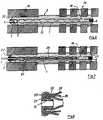
- the injection anchor shown in FIGS. 1 to 5 consists of a tube 1 and an elastic jacket 2 extending over the entire length of the tube, the ends 3, 4 of which are turned into the tube ends and are clamped to the tube by means of rivet-type fastening elements 5, 6 .
- the rivet-type fastening means each have a through channel 7, and a closure piece 8 is pressed tightly into the through channel of the rear fastening means.
- the tube 1 is, for example, a steel tube with a diameter of 10 millimeters and a wall thickness of 1 millimeter.
- the tube 1 is provided with opposing, rounded indentations 9, 10 over its length at regular intervals and, with the exception of its round end sections 11, 12, alternately each has a flat-oval cross-sectional area 14 according to the cross-sectional view according to FIG. 4 and approximately round or almost-round cross-sectional area 15 according to the cross-sectional view according to FIG. 5.
- the tube is narrowed to about half the tube diameter D.
- the indentations are made in such a way that the tube is continuously corrugated.
- the tube is provided with a larger radial outlet hole 16, and several comparatively smaller outlet holes 17 are distributed along its length.
- FIG. 6 illustrates an application example of the injection anchor according to FIGS. 1 to 5.
- Injection mass has been pressed through the through-channel of the front rivet-like fastening means 5, which initially fills the interior of the tube 1, then radially outwards through the outlet bore 16 and, if necessary, through the outlet bores 17 and spreads the elastic jacket 2 on the one hand until it abuts the borehole wall and on the other hand causes the elastic jacket 2 to bulge into cavities.
- injection compounds that set relatively quickly are usually used, so that there is no greater reflux pressure after the sprayer has been set down.
- a positioning disk 22, 23 is clamped between the rivet head of the fastening means 5, 6 and the ends of the tube 1, which is adapted approximately to the diameter of the borehole 20 and ensure a coaxial alignment of the tube 1.
- a connecting bolt 24 which is inserted or screwed into the tube 1 from the front and which has a non-smooth surface, e.g. carries an external thread 25 and the end protruding from the tube 1 can, depending on the design, be used as a hook, eyelet, threaded rod, etc. for attaching further elements.
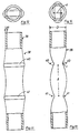
- the tube 26 is provided with a crimped edge 27 at its front end and a rivet-like fastening element 29 is provided for clamping the inserted hose 28, the shaft of which has a widening 30 inwards of the flange 27 and with high clamping pressure into it Tube 26 is pressed.
- the through-channel of the fastening element 29 is here with an internal thread 31 provided, into which a pull-out tool can be screwed. If the injection anchor according to FIG. 8 is inserted into a borehole, its pull-out strength is checked after the hardening time in that such a pull is exerted on the fastening element 29 by means of the pull-out tool that it is pulled off the tube 26.
- FIG. 9 and 10 show an alternative embodiment of an injection anchor 32, the tube 33 of which is provided with indentations 34 oriented parallel to one another only in its rear region, which is inserted into a borehole, and that the front has an almost equally long, round section 35.
- the tube is surrounded by an elastic hose 36, which is tightly attached, for example glued or clamped, to the rear end 37 of the tube.
- the hose 36 is fastened tightly to an annular flange 38, which is mounted in a longitudinally displaceable manner on the front, round section 35 of the tube.
- the tube 36 is not only radially but also longitudinally elastic and is inherently shorter than the tube 33, as can be seen in FIG. 9.
- FIG. 9 shows an alternative embodiment of an injection anchor 32, the tube 33 of which is provided with indentations 34 oriented parallel to one another only in its rear region, which is inserted into a borehole, and that the front has an almost equally long, round section 35.
- the tube is surrounded by an elastic hose 36
- FIG. 10 shows the same injection anchor as in FIG. 9, but here the injection anchor is completely inserted into a correspondingly deeper borehole, the longitudinally elastic hose 36 having been extended to the length of the tube 33 in the manner shown.
- 11 to 14 show in several views a pipe 39 intended for injection anchors according to the invention, which is here provided with two pairs of opposing impressions 40, 40 and 41, 41 and on which the optimal geometric dimensions are explained.
- the radius of curvature r of the bottom of the indentations 40, 41 is approximately equal to the wall thickness s of the tube. This is achieved by using a pressing tool whose apex curvature has this radius r .
- the distance l between two adjacent indentations 40, 41 is approximately twice the outer diameter D of the tube.
- the tube is constricted in the area of the opposing indentations to a thickness d of approximately 55% of its tube diameter D.
Abstract
Description
Die Erfindung betrifft einen in vorgebohrte Löcher einzusetzenden Injektionsanker, der aus einem, am hinteren Stirnende verschlossenen Rohr, das mit mindestens einem radialen Austrittsloch für die Injektionsmasse versehen ist, und aus einem elastischen, das Rohr umschließenden Mantel besteht.The invention relates to an injection anchor to be inserted into predrilled holes, which consists of a tube which is closed at the rear end, which is provided with at least one radial outlet hole for the injection compound, and an elastic jacket which surrounds the tube.
Durch das DE-GM 70 24 434 ist ein Injektionsanker bekannt, der ein glattwandiges Rohr aufweist, welches mit runden oder langlochartigen Austrittslöchern für die Injektionsmasse versehen ist, wobei um das Rohr ein Armierungsdraht gewickelt ist, der durch das Rohr umschließende und mit dem Rohr verbundene Ringe in seiner Lage fixiert ist. Auf einem Teil seiner Länge trägt das dortige Rohr bzw. seine Bewehrungswicklung einen elastischen Mantel, der beispielsweise bei Hohlblocksteinen oder Lochziegeln verhindern soll, daß Injektionsmasse unkontrolliert in Hohlräume verkriecht. Der bekannte Injektionsanker ist aber aufgrund seines vielteiligen Aufbaus verhältnismäßig teuer in der Herstellung und umständlich in der Handhabung. Der äußere Mantel kann beim Einschieben in ein Bohrloch verrutschen, so daß er seine Absperrfunktion gegenüber mauerwerkseitigen Hohlräumen verliert. Darüber hinaus ist die Auszugsfestigkeit des glattwandigen Rohres aus dem Injektionspfropfen nur sehr begrenzt.From DE-GM 70 24 434 an injection anchor is known which has a smooth-walled tube, which is provided with round or slot-like outlet holes for the injection compound, with a reinforcing wire being wound around the tube, the wire enclosing and connected to the tube Rings is fixed in position. Over a part of its length, the pipe there or its reinforcement winding has an elastic jacket which, for example in the case of hollow blocks or perforated bricks, is to prevent injection molding material from creeping into cavities in an uncontrolled manner. The well-known injection anchor is due to its multi-part construction relatively expensive to manufacture and cumbersome to use. The outer casing can slip when inserted into a borehole, so that it loses its shut-off function in relation to cavities on the masonry side. In addition, the pull-out strength of the smooth-walled tube from the injection plug is very limited.
Es sind ferner Injektionsanker bekannt, die aus einer Vollmaterialstange bestehen, die entweder einen eingebohrten Injektionskanal oder außen längs der Ankerstange verlaufende Injektionsröhrchen aufweisen. Auch diese bekannten Ausführungsformen sind verhältnismäßig teuer in der Herstellung.Injection anchors are also known which consist of a solid material rod, which either have a drilled injection channel or injection tubes running outside along the anchor rod. These known embodiments are also relatively expensive to manufacture.
Der Erfindung liegt die Aufgabe zugrunde, einen Injektionsanker zu schaffen, der preiswert als Massenartikel herstellbar ist, dessen Handhabung einfach ist und der eine hohe Auszugsfestigkeit besitzt, und zwar sowohl hinsichtlich des gesamten Injektionspfropfens aus der vorgebohrten Bohrung als auch hinsichtlich des Auszuges des Rohres aus dem Injektionspfropfen heraus.The invention has for its object to provide an injection anchor that is inexpensive to manufacture as a mass article, that is easy to use and that has a high pull-out strength, both with regard to the entire injection plug from the predrilled bore and with regard to the pulling out of the tube from the Injection plug out.
Ausgehend von einem gattungsgemäßen Injektionsanker wird die Lösung dieser Aufgabe erfindungsgemäß dadurch erreicht, daß das Rohr über seine Länge hinweg mit sich diametral gegenüberliegenden, abgerundeten Eindrückungen versehen ist und, mit Ausnahme seiner rundbelassenen Endabschnitte, jeweils abwechselnde flach-ovale Querschnittsbereiche und etwa runde oder fast runde Querschnittsbereiche aufweist und daß der elastische Mantel als ein über die gesamte Länge des Rohres sich erstreckender Schlauch ausgebildet ist, der mit seinen Enden jeweils in die Rohrenden eingestülpt und mittels nietartiger Befestigungsmittel am Rohr festgeklemmt ist.Starting from a generic injection anchor, the solution to this problem is achieved according to the invention in that the tube is provided with diametrically opposed, rounded indentations over its length and, with the exception of its round end sections, alternating flat-oval cross-sectional areas and approximately round or almost round Has cross-sectional areas and that the elastic jacket is designed as a tube extending over the entire length of the tube, the ends of which are inserted into the tube ends and clamped to the tube by means of rivet-type fastening means.
Ein solcher Injektionsanker ist nur aus wenigen Teilen ausgebaut, wobei für das Rohr abgelängte Stücke händelsüblicher Rohre und für den elastischen Mantel abgelängte Schlauchstücke verwendet werden können, wobei der Mantel vorteilhafterweise aus textilem Gewebe oder Gewirke besteht, das bis zu einem bestimmten Maße radial aufweitbar ist. Rohr und Mantel sind unter Verwendung einfacher, nietartiger Befestigungsmittel sicher miteinander verbunden, so daß der Mantel beim Einschieben in ein Bohrloch nicht verrutschen kann. Beim Einpressen der Injektionsmasse wird der Mantel an die Bohrlochwandung angepreßt, wobei durch den für die Injektionsmasse begrenzt durchlässigen Mantel Injektionsmasse hindurchtritt, so daß eine adhäsive Verbindung mit der Bohrlochwandung erreicht wird. Der Mantel beult sich dabei in Hohlräume aus, so daß der gebildete Injektionspfropfen auch formschlüssig im Mauerwerk oder dgl. gehalten ist. Das Rohr sitzt aufgrund seiner vielen Eindrückungen ebenfalls formschlüssig in dem sich innerhalb und außerhalb des Rohres ausbildenden Injektionspfropfen, so daß das Rohr selbst eine hohe Auszugsfestigkeit aufweist. Durch die Eindrückungen erfährt das Rohr eine Materialvorreckung, so daß sich das gewellte Rohr auch nicht unter hohen Zugbelastungen rückverformt. Der Injektionsanker läßt sich somit als billiger Massenartikel in Längen bis zu mehreren Metern und mit Durchmessern von mehreren Zentimetern, z. B. fünf Zentimetern, herstellen und er ist in seiner Handhabung narrensicher.Such an injection anchor is made up of only a few parts, with lengths of commercially available tubes cut to length for the tube and tube lengths cut to length for the elastic jacket can be used, the jacket advantageously consisting of textile fabric or knitted fabric which can be radially expanded to a certain extent. The tube and the jacket are securely connected to one another using simple, rivet-like fastening means, so that the jacket cannot slip when inserted into a borehole. When the injection compound is pressed in, the jacket is pressed against the borehole wall, with the injection compound passing through the jacket, which is permeable to the injection compound to a limited extent, so that an adhesive connection with the borehole wall is achieved. The The jacket bulges into cavities, so that the injection plug formed is also held in a form-fitting manner in the masonry or the like. Due to its many indentations, the tube also sits positively in the injection plug that forms inside and outside the tube, so that the tube itself has a high pull-out strength. The tube undergoes a material pre-stretching due to the indentations, so that the corrugated tube does not deform back even under high tensile loads. The injection anchor can thus be a cheap mass article in lengths of up to several meters and with diameters of several centimeters, for. B. five centimeters, and it is foolproof in its handling.
Gemäß einer bevorzugten Ausführungsform der Erfindung kann vorgesehen werden, daß das Rohr im Bereich der sich gegenüberliegenden Eindrückungen auf etwa halben Druchmesser eingeengt ist und daß das Rohr kontinuierlich, d. h. unter Vermeidung scharfer Kanten, gewellt ist. Durch diese Formgebung werden örtliche Spitzenbelastungen bei auf den Anker ausgeübten Zug-oder Druckkräften vermieden, so daß der Gefahr eines Brechens des Rohres oder des Injektionspfropfens vorgebeugt ist.According to a preferred embodiment of the invention it can be provided that the tube is narrowed to about half the diameter in the area of the opposing indentations and that the tube is continuous, i. H. avoiding sharp edges. This shape avoids local peak loads when tensile or compressive forces are exerted on the anchor, so that the risk of the pipe or the injection plug being broken is prevented.
Vorteilhafterweise werden an beiden Enden die gleichen nietartigen Befestigungsmittel verwendet, die einen Druchgangskanal aufweisen, wobei in das hintere Befestigungsmittel ein Verschlußstück eingepreßt ist, welches somit die Festklemmung des eingestülpten Schlauchendes am Rohr noch verbessert.Advantageously, the same rivet-like fasteners are used at both ends, which have a passage channel, with a closure piece being pressed into the rear fastener, which thus further improves the clamping of the tube end in the tube.
Am vorderen Anker kann der eingestülpte Schlauch einen über den Schaft des Befestigungsmittels in das Rohr hineinragenden Endabschnitt aufweisen, der beim Absetzen des Spritzgerätes als Rückschlagventil wirkt und ein Auslaufen der Injektionsmasse verhindert.On the front anchor, the hose that is slipped in can have an end section protruding into the tube via the shaft of the fastening means, which end section acts as a check valve when the sprayer is set down and prevents the injection compound from escaping.
Nach weiteren Merkmalen der Erfindung kann vorgesehen werden, daß das Rohr nahe am hinteren Ende mit einem größeren Austrittsloch und über seine Länge verteilten mit vergleichsweise kleineren Austrittslöchern versehen ist. Durch diese Maßnahmen wird einerseits sichergestellt, daß die Injektionsmasse nahe des hinteren Endes des Injektionsankers in den Bohrlochraum austritt und diesen von hinten nach vorne hin allmählich füllt. Andererseits wird aber insbesondere bei schnellabbindenden Injektionsmassen durch die vorderen, kleinen Löcher sichergestellt, daß auch dann noch der gesamte Bohrlochraum mit Injektionsmasse gefüllt wird.According to further features of the invention it can be provided that the tube is provided near the rear end with a larger outlet hole and distributed over its length with comparatively smaller outlet holes. These measures ensure, on the one hand, that the injection mass exits into the borehole space near the rear end of the injection anchor and fills it gradually from the back to the front. On the other hand, however, especially in the case of fast-setting injection compounds, the small front holes ensure that the entire borehole space is still filled with injection compound.
In Weiterbildung der Erfindung kann vorgesehen werden, daß zwischen dem Nietkopf der Befestigungsmittel und den Rohrenden jeweils eine dem Bohrlochdurchmesser angepaßte Positionierscheibe eingeklemmt ist. Durch diese Positionierscheibe wird eine koaxiale Ausrichtung des Injektionsankers auf das Bohrloch gewährleistet.In a further development of the invention it can be provided that a positioning disk adapted to the borehole diameter is clamped between the rivet head of the fastening means and the pipe ends. This positioning disc ensures a coaxial alignment of the injection anchor with the borehole.
Dem Injektionsanker können der Erfindung zufolge ferner noch in das Rohr einsteckbare Anschlußbolzen zugeordnet sein, deren vorderer Teil eine nicht glatte Oberfläche, z.B. ein Außengewinde, aufweist. Diese Anschlußbolzen werden noch vor vollständigem Aushärten der Injektionsmasse in das Rohr eingesteckt, und das herausragende Ende des Anschlußbolzens kann je nach seiner Ausbildung als Haken, öse usw. zur Befestigung oder Aufhängung weiterer Bauteile verwendet werden.According to the invention, the injection anchor can also be assigned connecting bolts which can be inserted into the tube and whose front part has a non-smooth surface, e.g. has an external thread. These connecting bolts are inserted into the tube before the injection compound has completely hardened, and the protruding end of the connecting bolt can, depending on its design, be used as a hook, eye, etc. for fastening or suspending further components.
Ferner kann der Erfindung zufolge noch vorgesehen werden, daß das Rohr an seinem vorderen Ende eingebördelt ist, daß das Befestigungsmittel mit hoher Klemmkraft in das Rohr eingesteckt und sein Schaft mit einer Innengewindebohrung versehen ist. Bei der Massenproduktion ergibt sich hier immer ein annähernd gleich stabiler Sitz des Befestigungsmittels am Rohr, wobei die Zugkraft, mit der das Befestigungsmittel vom Rohr mittels eines geeigneten Werkzeuges abgezogen werden kann, gleich oder etwas größer gewählt wird als die verlangte Mindestauszugsfestigkeit des Injektionsankers. Es ist somit möglich, eingesetzte Injektionsanker auf ihre Auszugsfestigkeit zu prüfen, in dem man das vordere Befestigungsmittel vom Rohr abzieht. Man kann auf diese Weise zerstörungsfrei prüfen, ob die gesetzten Injektionsanker die vorgeschriebene Auszugsfestigkeit besitzen.Furthermore, according to the invention it can be provided that the tube is crimped at its front end, that the fastener is inserted into the tube with a high clamping force and that its shaft is provided with an internally threaded bore. In mass production, the result is always almost the same stable attachment of the fastener to the pipe, the tensile force with which the fastener can be pulled off the pipe using a suitable tool is chosen to be equal to or slightly greater than the required minimum pull-out strength of the injection anchor. It is therefore possible to test the inserted anchors for their pull-out strength by pulling the front fastener off the pipe. In this way, you can check non-destructively whether the injection anchors have the required pull-out strength.
Ausgehend von einem gattungsgemäßen Injektionsanker ist erfindungsgemäß als alternative Lösung vorgesehen, daß das Rohr zumindest auf einem großen Teil seiner Länge mit sich diametral gegenüberliegenden, abgerundeten Eindrückungen versehen ist und, mit Ausnahme seiner rundbelassenen Endabschnitte, jeweils abwechselnd flach-ovale Querschnittsbereiche und runde oder fast-runde Querschnittsbereiche aufweist, und daß der Mantel als ein längselastischer Schlauch oder Strumpf ausgebildet ist, der einerseits am Einschubende des Rohres befestigt und andererseits an einem Flanschring befestigt ist, der verschieblich auf einem vorderen, rundbelassenen Abschnitt des Rohres verschiebbar gelagert ist.Starting from a generic injection anchor, the invention provides as an alternative solution that the tube is provided with diametrically opposed, rounded indentations at least over a large part of its length and, with the exception of its round end sections, alternately flat-oval cross-sectional areas and round or almost has round cross-sectional areas, and that the jacket is designed as a longitudinally elastic hose or stocking, which is attached on the one hand to the insertion end of the tube and on the other hand is attached to a flange ring which is slidably mounted on a front, round portion of the tube.
Durch diese Maßnahmen ist ein Injektionsanker erreicht, der wahlweise vollkommen oder mehr oder weniger weit vorragend in ein Bohrloch eingesteckt werden kann. Sein ggfs. herausragendes Ende kann zum Anschluß weiterer Elemente genutzt und z.B. zu einer Tragkonsole ergänzt werden.These measures result in an injection anchor that can either be inserted completely or more or less protrudingly into a borehole. Its possibly protruding end can be used to connect further elements and e.g. to be supplemented to a support bracket.
In den Unteransprüchen 10 bis 14 sind weitere Merkmale angegeben, durch die eine optimale Bruch- und Zugfestigkeit, insbesondere Formbeständigkeit gegenüber Zugkräften, und eine gute Einbettung des Injektionsankers in der Injektionsmasse erreicht werden.Further features are specified in
Die Erfindung wird im folgenden anhand der Zeichnung näher beschrieben, in der zeigen:
- Fig. 1
- in Draufsicht einen Injektionsanker nach der Erfindung,
- Fig. 2
- den Injektionsanker in einem Längsschnitt,
- Fig. 3
- eine Draufsicht auf das Rohr des Injektionsankers, in Fig. 2 in Richtung des Pfeiles III gesehen,
- Fig. 4
- einen Schnitt gemäß der Linie IV-IV in Fig. 3,
- Fig. 5
- einen Schnitt gemäß der Linie V-V in Fig. 3,
- Fig. 6
- ein Beispiel für die Anwendung des Injektionsankers bei einem zweischaligen Mauerwerk,
- Fig. 7
- eine abgewandelte Ausführungsform in Verbindung mit einem Anwendungsbeispiel,
- Fig. 8
- eine abgewandelte Ausführungsform für das vordere Ende des Injektionsankers,
- Fig. 9
- eine alternative Ausführungsform in Verbindung mit einem Anwendungsbeispiel,
- Fig. 10
- die Ausführungsform nach Fig. 9 in Verbindung mit einem anderen Anwendungsbeispiel,
- Fig. 11 bis 14
- mehrere Ansichten auf das Rohr eines Injektionsankers nach der Erfindung.
- Fig. 1
- in plan view an injection anchor according to the invention,
- Fig. 2
- the injection anchor in a longitudinal section,
- Fig. 3
- a plan view of the tube of the injection anchor, seen in Fig. 2 in the direction of arrow III,
- Fig. 4
- 4 shows a section along the line IV-IV in FIG. 3,
- Fig. 5
- 4 shows a section along the line VV in FIG. 3,
- Fig. 6
- an example of the use of the injection anchor in a double-layer masonry,
- Fig. 7
- a modified embodiment in connection with an application example,
- Fig. 8
- a modified embodiment for the front end of the injection anchor,
- Fig. 9
- an alternative embodiment in connection with an application example,
- Fig. 10
- 9 in connection with another application example,
- 11 to 14
- several views of the tube of an injection anchor according to the invention.
Der in den Fig. 1 bis 5 gezeigte Injektionsanker besteht aus einem Rohr 1 und einem sich über die gesamte Länge des Rohres erstreckenden elastischen Mantel 2, dessen Enden 3, 4 in die Rohrenden eingestülpt sind und mittels nietartiger Befestigungselemente 5, 6 am Rohr festgeklemmt sind. Die nietartigen Befestigungsmittel weisen jeweils einen Durchgangskanal 7 auf, und in den Durchgangskanal des hinteren Befestigungsmittels ist ein Verschlußstück 8 stramm eingepreßt.The injection anchor shown in FIGS. 1 to 5 consists of a
Bei dem Rohr 1 handelt es sich beispielsweise um ein Stahlrohr von 10 Millimetern Durchmesser und 1 Millimeter Wandstärke. Das Rohr 1 ist über seine Länge hinweg in regelmäßigen Abständen mit sich gegenüberliegenden, abgerundeten Eindrückungen 9, 10 versehen und weist, mit Ausnahme seiner rundbelassenen Endabschnitte 11, 12, jeweils abwechselnd einen flach-ovalen Querschnittsbereich 14 gemäß Querschnittsdarstellung nach Fig. 4 und einen etwa runden oder fast-runden Querschnittsbereich 15 gemäß Querschnittsdarstellung nach Fig. 5 auf. Im Bereich der Eindrückungen 9, 10 ist das Rohr bis auf etwa halben Rohrdurchmesser D eingeengt. Die Eindrückungen sind derart vorgenommen, daß das Rohr kontinuierlich gewellt ist. Nahe seines hinteren Endes ist das Rohr mit einem größeren radialen Austrittsloch 16 versehen, und über seine Länge hinweg, sind mehrere vergleichsweise kleinere Austrittslöcher 17 verteilt.The
Fig. 6 veranschaulicht ein Anwendungsbeispiel des Injektionsankers nach den Fig. 1 bis 5. In einem aus den beiden Schalen 18, 19 bestehenden Mauerwerk sind Bohrlöcher 20 vorgebohrt, in die der Injektionsanker eingeschoben ist. Durch den Durchgangskanal des vorderen nietartigen Befestigungsmittels 5 hindurch, ist Injektionsmasse eingepreßt worden, die zunächst den Innenraum des Rohres 1 füllt, dann durch die Austrittsbohrung 16 und ggfs. durch die Austrittsbohrungen 17 radial nach außen tritt und den elastischen Mantel 2 einerseits bis Anlage an die Bohrlochwandung spreizt und andererseits eine Ausbeulung des elastischen Mantels 2 in Hohlräume bewirkt. In der Praxis werden meist verhältnismäßig schnell abbindende Injektionsmassen verwendet, so daß nach Absetzen des Spritzgerätes kein größerer Rückflußdruck besteht. Die durch das vordere Befestigungsmittel 5 hindurchgestülpten Endabschnitte 3 des elastischen Schlauches sperren zudem den Durchlaßkanal 7 gegen einen Rückfluß nach Art eines Rückschlagventils ab. Nach Aushärten der Injektionsmasse sitzt sowohl das Rohr 1 formschlüssig im Injektionsmassepfropfen 21 und ist dieser Pfropfen aufgrund der Ausbeulungen ebenfalls formschlüssig an den Mauerwerksschalen 19, 20 gehalten, so daß der Anker eine hohe Auszugsfestigkeit besitzt.FIG. 6 illustrates an application example of the injection anchor according to FIGS. 1 to 5. In a masonry consisting of the two
Beim Ausführungsbeispiel nach Fig. 7 ist zwischen dem Nietkopf der Befestigungsmittel 5, 6 und den Enden des Rohres 1 noch jeweils eine Positionierscheibe 22, 23 eingeklemmt, die etwa dem Durchmesser des Bohrloches 20 angepaßt ist und eine koaxiale Ausrichtung des Rohres 1 sicherstellen. Ferner ist in Fig. 7 noch ein in das Rohr 1 von vorne eingesteckter oder eingeschraubter Anschlußbolzen 24 gezeigt, der in seinem vorderen Bereich eine nicht-glatte Oberfläche, z.B. ein Außengewinde 25 trägt und dessen aus dem Rohr 1 herausragendes Ende je nach Ausbildung als Haken, öse, Gewindestange usw. zur Anbringung weiterer Elemente verwendet werden kann.In the embodiment according to FIG. 7, a
Beim Ausführungsbeispiel nach Fig. 8 ist das Rohr 26 an seinem vorderen Ende mit einem eingebördelten Rand 27 versehen und ist zur Festklemmung des eingestülpten Schlauches 28 ein nietartiges Befestigungselement 29 versehen, dessen Schaft einwärts der Bördelung 27 eine Verbreiterung 30 aufweist und mit hohem Klemmdruck in das Rohr 26 eingepreßt ist. Der Durchgangskanal des Befestigungselementes 29 ist hier mit einem Innengewinde 31 versehen, in das ein Ausziehwerkzeug eingeschraubt werden kann. Wenn der Injektionsanker gemäß Fig. 8 in ein Bohrloch eingesetzt ist, wird nach der Aushärtezeit seine Auszugsfestigkeit geprüft, indem mittels des Ausziehwerkzeuges ein solcher Zug auf das Befestigungselement 29 ausgeübt wird, daß dieses vom Rohr 26 abgezogen wird. Wenn die Auszugsfestigkeit des Ankers im Mauerwerk zu gering ist, wird der Injektionsanker bei einem solchen Prüfvorgang mit herausgezogen. Wird dagegen nur das Befestigungselement 29 abgezogen, hat man zerstörungsfrei die ausreichende Auszugsfestigkeit des gesetzten Injektionsankers überprüft.In the exemplary embodiment according to FIG. 8, the
Die Fig. 9 und 10 zeigen eine alternative Ausführungsform eines Injektionsankers 32, dessen Rohr 33 nur in seinem hinteren, in ein Bohrloch eingesteckten Bereich mit parallel zueinander ausgerichteten Eindrückungen 34 versehen ist, und daß vorne einen fast gleich langen, rundbelassenen Abschnitt 35 aufweist. Das Rohr ist von einem elastischen Schlauch 36 umgeben, der am hinteren Ende 37 des Rohres dicht befestigt, z.B. angeklebt oder angeklemmt ist. An seinem vorderen Ende ist der Schlauch 36 dicht an einem Ringflansch 38 befestigt, der längsverschieblich auf dem vorderen, rundbelassenen Abschnitt 35 des Rohres gelagert ist. Der Schlauch 36 ist nicht nur radial-, sondern auch längselastisch und ist von Hause aus kürzer als das Rohr 33, wie aus Fig. 9 ersichtlich ist. In Fig. 9 ist der Injektionsanker nur teilweise bis zur Anlage seines Ringflansches 38 an der Bohrlochmündung in das Bohrloch eingesteckt und ragt sein rundbelassener vorderer Abschnitt 35 ein weites Stück noch aus dem Bohrloch heraus. Fig. 10 zeigt den gleichen Injektionsanker wie in Fig. 9, jedoch ist der Injektionsanker hier vollständig in ein entsprechend tieferes Bohrloch eingesteckt, wobei der längselastische Schlauch 36 in der gezeigten Weise auf die Länge des Rohres 33 ausgelängt worden ist.9 and 10 show an alternative embodiment of an
Die Fig. 11 bis 14 zeigen in mehreren Ansichten ein für Injektionsanker nach der Erfindung bestimmtes Rohr 39, das hier mit jeweils zwei Paaren von sich gegenüberliegenden Eindrückungen 40, 40 und 41, 41 versehen ist und an dem die optimalen geometrischen Abmessungen erläutert sind. Der Krümmungsradius r des Grundes der Eindrückungen 40, 41 ist hier etwa gleich der Wandstärke s des Rohres. Dies wird durch Verwendung eines Drückwerkzeuges erreicht, dessen Scheitelkrümmung diesen Radius r aufweist.11 to 14 show in several views a
Der Abstand l zwischen zwei benachbarten Eindrückungen 40, 41 beträgt hier etwa das Doppelte des Außendurchmessers D des Rohres. Das Rohr ist im Bereich der sich gegenüberliegenden Eindrückungen bis auf eine Dicke d von etwa 55% seines Rohrdurchmessrs D eingeengt.The distance l between two
Claims (14)
- Injection anchor to be inserted into pre-drilled holes, consisting of a pipe, closed off at its rear end and equipped with at least one radial exit-hole for the injection mass, and of an elastic sleeve surrounding the pipe, characterized in that the pipe (1) is equipped along its length with rounded surface-depressions (9,10) lying diametrically opposite one another, and, with the exception of its end sections (11,12) which are left round, has alternating areas of shallow-oval cross-section (14) and round or almost round cross-section (15), and in that the elastic sleeve (2) is designed as a hose, extending over the whole length of the pipe (1), whose ends (3,4) are turned over into the ends of the pipe and clamped to the pipe (1) by stud-like fasteners (5,6).
- Injection anchor as claimed in Claim 1, characterized in that in the area of the surface-depressions (9,10) lying opposite one another the pipe (1) is narrowed to around half the pipe diameter (D) and in that the wall of the pipe (1) is continuously undulated.
- Injection anchor as claimed in Claims 1 or 2, characterized in that the stud-like fasteners (5,6) have a channel (7) passing through them and in that a stopper (8) is pressed into the rear fastener (6).
- Injection anchor as claimed in Claims 2 or 3, characterized in that at the front end of the anchor the folded-over hose has an end section (13) designed as a reflux-check-valve, projecting via the shaft of the fastener (5) into the pipe (1)
- Injection anchor as claimed in one or more of the previous claims, characterized in that the pipe (1) is equipped near its rear end with a larger exit bore-hole (16) and over its length with relatively smaller exit bore-holes (17).
- Injection anchor as claimed in one of Claims 1 to 5, characterized by an attachment rod (24) which may be inserted into the pipe (1), its insertion end having a non-smooth surface, e.g an exterior thread (25).
- Injection anchor as claimed in one of Claims 1 to 6, characterized in that a positioning washer (22,23), appropriate to the diameter of the bore-hole, is fixed between the heads of each of the fastening studs (5,6) and the ends of the pipe (1).
- Injection anchor as claimed in one or more of Claims 1 to 7, characterized in that the pipe (26) has at its front end a crimped edge (27), in that the fastener (29) is jammed forcibly into the pipe and in that its shaft is equipped with an interior threaded bore (31).
- Injection anchor to be inserted into pre-drilled holes, consisting of a pipe, closed off at its rear end and equipped with at least one radial exit-hole for the injection mass, and of an elastic sleeve surrounding the pipe, characterized in that the pipe (33) is equipped at least along a large part of its length with rounded surface-depressions (34) lying diametrically opposite one another, and, with the exception of its end sections which are left round, has alternating areas of shallow-oval cross-section and round or almost round cross-section, and in that the sleeve is designed as a hose (36) or stocking, elastic in a longitudinal direction, which at one end is fastened to the insertion end (37) of the pipe (33) and whose other end is fastened to a flange ring (38), which is positioned so as to be slid or pushed along a forward section (35) of the pipe (33), which is left round.
- Injection anchor as claimed in Claim 1 or 9, characterized in that the radius of curvature (r) of the base of the surface-depressions (40,41) is at least as great as the thickness (s) of the walls of the pipe (39) and not greater than half the diameter (D) of the pipe.
- Injection anchor as claimed in Claim 10, characterized in that the distance (l) between adjacent surface-depressions (40,41) is at least double and at most four times the diameter (D) of the pipe (39).
- Injection anchor as claimed in Claims 10 or 11, characterized in that the pipe (39) in the area of the surface-depressions (40,40) lying opposite one another is narrowed to a thickness (d) of about 55% of its own diameter (D).
- Injection anchor as claimed in Claim 9, characterized in that the pipe (33) consists of sections which are continuously undulated and of sections which are left round, wherein the length of those areas which are left round (35) is at least double the distance (l) between two adjacent surface-depressions (34) in its undulated section.
- Injection anchor as claimed in Claims 1 or 9, characterized in that the pipe is equipped with parallel surface-depressions and roughly halfway between each of these with a surface depression at right angles to them.
Applications Claiming Priority (2)
| Application Number | Priority Date | Filing Date | Title |
|---|---|---|---|
| DE3608775A DE3608775C2 (en) | 1986-03-15 | 1986-03-15 | Injection anchor to be inserted into pre-drilled holes |
| DE3608775 | 1986-03-15 |
Publications (3)
| Publication Number | Publication Date |
|---|---|
| EP0241708A2 EP0241708A2 (en) | 1987-10-21 |
| EP0241708A3 EP0241708A3 (en) | 1992-09-02 |
| EP0241708B1 true EP0241708B1 (en) | 1994-06-22 |
Family
ID=6296497
Family Applications (1)
| Application Number | Title | Priority Date | Filing Date |
|---|---|---|---|
| EP87103494A Expired - Lifetime EP0241708B1 (en) | 1986-03-15 | 1987-03-11 | Injection anchor to be inserted into pre-drilled holes |
Country Status (5)
| Country | Link |
|---|---|
| US (1) | US4773794A (en) |
| EP (1) | EP0241708B1 (en) |
| AT (1) | ATE107744T1 (en) |
| DE (2) | DE3608775C2 (en) |
| ES (1) | ES2056793T3 (en) |
Families Citing this family (25)
| Publication number | Priority date | Publication date | Assignee | Title |
|---|---|---|---|---|
| US4860513A (en) * | 1988-01-25 | 1989-08-29 | Whitman Robert E | Roofing fastener |
| DE3805538A1 (en) * | 1988-02-23 | 1989-08-31 | Int Intec Co Ets | INJECTION ANCHOR TO BE INSERTED INTO PRE-DRILLED HOLES OF A MULTI-SHELLED BUILDING WALL |
| DE3812913A1 (en) * | 1988-04-18 | 1989-10-26 | Hilti Ag | DUEBEL WITH SEVENTHAL SLEEVE |
| EP0351668B1 (en) * | 1988-07-15 | 1992-10-14 | Mächtle GmbH | Dowel for façades |
| DE3900671C1 (en) * | 1989-01-12 | 1990-03-08 | Messerschmitt-Boelkow-Blohm Gmbh, 8012 Ottobrunn, De | Process for securing the position of a metal insert in a plastic wall |
| DE4010051C1 (en) * | 1990-03-29 | 1991-08-08 | Upat Gmbh & Co, 7830 Emmendingen, De | |
| US5134828A (en) * | 1990-12-14 | 1992-08-04 | High Industries, Inc. | Connection for joining precast concrete panels |
| GB2263958B (en) * | 1992-02-05 | 1995-06-07 | Exchem Plc | Anchoring of fixing elements in bores |
| DE9310816U1 (en) * | 1993-07-20 | 1994-11-24 | Fischer Artur Werke Gmbh | Facing anchor |
| US5483781A (en) * | 1994-06-13 | 1996-01-16 | Illinois Tool Works Inc. | Construction fastener assembly |
| US5553436A (en) * | 1994-09-16 | 1996-09-10 | Illinois Tool Works Inc. | Screen for anchoring a fastener to a hollow block with an adhesive |
| GB9611641D0 (en) * | 1996-06-04 | 1996-08-07 | Edscer William G | Method of positioning retrospective reinforcement in masonry structures |
| GB9816155D0 (en) * | 1998-07-25 | 1998-09-23 | Internstional Intec Trading | Improvements relating to masonry anchorages |
| DE20001930U1 (en) * | 2000-02-05 | 2000-09-07 | Jora Tec Gmbh Berg Tunnelbau U | Injection anchor |
| DE10038801A1 (en) * | 2000-08-09 | 2002-02-21 | Fischer Artur Werke Gmbh | Injection-securable anchor |
| KR100444726B1 (en) * | 2002-03-20 | 2004-08-16 | 이창남 | Spacer of Ornamental Brick Wall |
| US6837018B1 (en) * | 2003-06-10 | 2005-01-04 | Simpson Strong-Tie Company, Inc. | Connection and method for setting a composite anchor with an apertured screen in a substrate |
| US7404274B2 (en) * | 2003-11-12 | 2008-07-29 | Hayes John T | Masonry wall anchoring system |
| AT501441A3 (en) * | 2004-12-23 | 2009-12-15 | Atlas Copco Mai Gmbh | METHOD FOR SETTING MOUNTAIN ANCHORS AND ATTACHABLE POOL ANCHORS USING THIS METHOD |
| NL1036178C2 (en) * | 2008-11-10 | 2010-05-11 | Jahn H H O | METHOD AND COUPLING BODY FOR REINFORCING A WALL. |
| WO2012174257A2 (en) * | 2011-06-14 | 2012-12-20 | Wathne John M | System of tying, cleaning and re-cementing masonry using port anchors |
| DE102011078696A1 (en) * | 2011-07-05 | 2013-01-10 | Smp Swiss Macro Polymers Ag | Assembly of fabric sleeve and curing material for securing an anchoring element in a borehole |
| US20160251848A1 (en) * | 2013-10-11 | 2016-09-01 | Masonry Solutions International | System and method for anchoring a structure |
| GB2558663B (en) * | 2017-01-17 | 2021-04-07 | Foster Terence | Sock anchor unit |
| US11421433B2 (en) | 2020-07-03 | 2022-08-23 | Craft Pro Masonry Restorations, Inc. | Anchor plate system for reinforcing masonry walls |
Citations (1)
| Publication number | Priority date | Publication date | Assignee | Title |
|---|---|---|---|---|
| DE7024434U (en) * | 1970-06-30 | 1971-02-11 | Mueller P | Wall anchors with automatic filling and adhesive extrusion in predefined zones |
Family Cites Families (20)
| Publication number | Priority date | Publication date | Assignee | Title |
|---|---|---|---|---|
| US1564947A (en) * | 1923-06-25 | 1925-12-08 | Lloyd G Copeman | Bushing construction |
| US3108404A (en) * | 1960-06-07 | 1963-10-29 | Lyle N Lamb | Anchor device for hollow masonry type walls |
| US3395625A (en) * | 1966-03-04 | 1968-08-06 | Monsanto Co | Anchored synthetic turf |
| CH564654A5 (en) * | 1973-01-17 | 1975-07-31 | Otta Ladislav | Ground anchor for bore mounting - has deformable body for making friction contact with borehole wall |
| US4001989A (en) * | 1974-10-30 | 1977-01-11 | Artur Fischer | Apparatus for fixing an object to a low-strength support structure |
| SE418882B (en) * | 1974-11-14 | 1981-06-29 | Fischer Artur | DEVICE FOR ANCHORING A FASTENER |
| US4096672A (en) * | 1974-11-14 | 1978-06-27 | Artur Fisher | Anchoring arrangement for securing an object to a support structure having an internal cavity |
| FR2328877A2 (en) * | 1974-11-14 | 1977-05-20 | Fischer Artur | METHOD FOR ANCHORING A FIXING ELEMENT |
| DE2723729C2 (en) * | 1977-05-26 | 1979-04-05 | Fischer, Artur, Dr.H.C., 7244 Waldachtal | Anchoring a fastening element in a borehole of a masonry having cavities |
| DE2830073A1 (en) * | 1978-07-08 | 1980-01-17 | Fischer Artur Dr H C | ANCHORING A FASTENING ELEMENT |
| SU848663A1 (en) * | 1978-09-28 | 1981-07-23 | Всесоюзный Ордена Ленина Проектно- Изыскательский И Научно-Исследова-Тельский Институт "Гидропроект" Им.C.Я.Жука | Ferroconcrete anchor |
| US4253781A (en) * | 1979-03-08 | 1981-03-03 | Philipp Holzmann Aktiengesellschaft | Method and an apparatus for providing a grouted anchorage against hydrostatic pressure |
| JPS5689700A (en) * | 1979-12-18 | 1981-07-21 | Kubota Ltd | Locking bolt |
| US4322183A (en) * | 1980-03-07 | 1982-03-30 | Armand Ciavatta | Friction rock stabilizer and installation lubricating cement apparatus and method |
| US4461600A (en) * | 1981-03-24 | 1984-07-24 | Willich Gmbh & Co. | Method of and device for solidifying rock in mine tunnels and the like |
| DE3138610C2 (en) * | 1981-09-29 | 1984-10-18 | Bergwerksverband Gmbh, 4300 Essen | Device for durable fastening of objects in boreholes |
| SE436781B (en) * | 1981-11-16 | 1985-01-21 | Atlas Copco Ab | SVELLKROPP |
| DE3218036A1 (en) * | 1982-05-13 | 1983-11-17 | Hilti AG, 9494 Schaan | Mounting element for anchoring in retaining material having hollow chambers |
| DE3225051A1 (en) * | 1982-07-05 | 1984-01-05 | Hilti AG, 9494 Schaan | Dowel for retaining materials having cavities |
| EP0134379A1 (en) * | 1983-07-20 | 1985-03-20 | BAUTEK S.r.l. | Anchor element for tie bars in civil works |
-
1986
- 1986-03-15 DE DE3608775A patent/DE3608775C2/en not_active Expired - Fee Related
-
1987
- 1987-03-11 AT AT87103494T patent/ATE107744T1/en not_active IP Right Cessation
- 1987-03-11 EP EP87103494A patent/EP0241708B1/en not_active Expired - Lifetime
- 1987-03-11 ES ES87103494T patent/ES2056793T3/en not_active Expired - Lifetime
- 1987-03-11 DE DE3750098T patent/DE3750098D1/en not_active Expired - Lifetime
- 1987-03-16 US US07/026,252 patent/US4773794A/en not_active Expired - Lifetime
Patent Citations (1)
| Publication number | Priority date | Publication date | Assignee | Title |
|---|---|---|---|---|
| DE7024434U (en) * | 1970-06-30 | 1971-02-11 | Mueller P | Wall anchors with automatic filling and adhesive extrusion in predefined zones |
Also Published As
| Publication number | Publication date |
|---|---|
| ES2056793T3 (en) | 1994-10-16 |
| DE3608775A1 (en) | 1987-09-17 |
| DE3750098D1 (en) | 1994-07-28 |
| US4773794A (en) | 1988-09-27 |
| ATE107744T1 (en) | 1994-07-15 |
| DE3608775C2 (en) | 1995-03-16 |
| EP0241708A3 (en) | 1992-09-02 |
| EP0241708A2 (en) | 1987-10-21 |
Similar Documents
| Publication | Publication Date | Title |
|---|---|---|
| EP0241708B1 (en) | Injection anchor to be inserted into pre-drilled holes | |
| DE4107790C1 (en) | ||
| EP0192913B1 (en) | Expansive dowel with an application indication | |
| DE3124685C2 (en) | ||
| WO1982004461A1 (en) | Anchoring bolt | |
| DE2112591A1 (en) | Expandable fastening device | |
| DE3007650C2 (en) | Expansion dowel for anchoring in drilled holes made conically widened inwards | |
| DE2135333C3 (en) | Hammer-in expansion anchor for anchoring in a drill hole in reinforced concrete | |
| EP0054681A1 (en) | Fastener means consisting of a plastic dowel and a fastening screw | |
| EP2513498B1 (en) | Anchor sleeve | |
| EP0056255B1 (en) | Device for fixing objects to a concrete wall | |
| DE2848478A1 (en) | EXPANSION DOWEL | |
| CH627241A5 (en) | ||
| DE4004207C2 (en) | Fastening device | |
| DE2046757C2 (en) | Plastic mounting plate for furniture fittings - has thin walled hollow rear anchoring studs radially expanded and axially compressed by driven in plug (AT 15.3.75) | |
| DE2927953A1 (en) | MOUNTAIN ANCHOR | |
| CH398937A (en) | Expansion anchor | |
| DE2043621A1 (en) | Dowels for a wall made of porous material such as aerated concrete | |
| DE3145319C2 (en) | ||
| DE19543214C2 (en) | Removable anchor dowel | |
| DE6907151U (en) | PLUG WITH LOCKING DEVICE | |
| DE3131758C2 (en) | Plastic dowels for lightweight building materials | |
| DE4203324C2 (en) | Bolt anchor with expansion sleeve | |
| DE1650962A1 (en) | Duebel, especially for fastening components to masonry | |
| DE2737857A1 (en) | Plastics dowel with spiral outer ribs - has shoulder spaced from screw insert end and steeply pitched ribs |
Legal Events
| Date | Code | Title | Description |
|---|---|---|---|
| PUAI | Public reference made under article 153(3) epc to a published international application that has entered the european phase |
Free format text: ORIGINAL CODE: 0009012 |
|
| AK | Designated contracting states |
Kind code of ref document: A2 Designated state(s): AT BE CH DE ES FR GB GR IT LI LU NL SE |
|
| RAP1 | Party data changed (applicant data changed or rights of an application transferred) |
Owner name: INTERNATIONAL INTEC PATENT HOLDING ESTABLISHMENT |
|
| PUAL | Search report despatched |
Free format text: ORIGINAL CODE: 0009013 |
|
| AK | Designated contracting states |
Kind code of ref document: A3 Designated state(s): AT BE CH DE ES FR GB GR IT LI LU NL SE |
|
| 17P | Request for examination filed |
Effective date: 19930216 |
|
| 17Q | First examination report despatched |
Effective date: 19930819 |
|
| GRAA | (expected) grant |
Free format text: ORIGINAL CODE: 0009210 |
|
| AK | Designated contracting states |
Kind code of ref document: B1 Designated state(s): AT BE CH DE ES FR GB GR IT LI LU NL SE |
|
| REF | Corresponds to: |
Ref document number: 107744 Country of ref document: AT Date of ref document: 19940715 Kind code of ref document: T |
|
| REF | Corresponds to: |
Ref document number: 3750098 Country of ref document: DE Date of ref document: 19940728 |
|
| ITF | It: translation for a ep patent filed |
Owner name: STUDIO JAUMANN |
|
| REG | Reference to a national code |
Ref country code: ES Ref legal event code: FG2A Ref document number: 2056793 Country of ref document: ES Kind code of ref document: T3 |
|
| GBT | Gb: translation of ep patent filed (gb section 77(6)(a)/1977) |
Effective date: 19940919 |
|
| ET | Fr: translation filed | ||
| REG | Reference to a national code |
Ref country code: GR Ref legal event code: FG4A Free format text: 3013148 |
|
| EAL | Se: european patent in force in sweden |
Ref document number: 87103494.8 |
|
| PLBE | No opposition filed within time limit |
Free format text: ORIGINAL CODE: 0009261 |
|
| STAA | Information on the status of an ep patent application or granted ep patent |
Free format text: STATUS: NO OPPOSITION FILED WITHIN TIME LIMIT |
|
| 26N | No opposition filed | ||
| REG | Reference to a national code |
Ref country code: GB Ref legal event code: IF02 |
|
| PGFP | Annual fee paid to national office [announced via postgrant information from national office to epo] |
Ref country code: NL Payment date: 20050309 Year of fee payment: 19 Ref country code: AT Payment date: 20050309 Year of fee payment: 19 |
|
| PGFP | Annual fee paid to national office [announced via postgrant information from national office to epo] |
Ref country code: CH Payment date: 20050311 Year of fee payment: 19 |
|
| PGFP | Annual fee paid to national office [announced via postgrant information from national office to epo] |
Ref country code: SE Payment date: 20050314 Year of fee payment: 19 Ref country code: LU Payment date: 20050314 Year of fee payment: 19 |
|
| PGFP | Annual fee paid to national office [announced via postgrant information from national office to epo] |
Ref country code: FR Payment date: 20060307 Year of fee payment: 20 Ref country code: GB Payment date: 20060307 Year of fee payment: 20 |
|
| PG25 | Lapsed in a contracting state [announced via postgrant information from national office to epo] |
Ref country code: AT Free format text: LAPSE BECAUSE OF NON-PAYMENT OF DUE FEES Effective date: 20060311 |
|
| PG25 | Lapsed in a contracting state [announced via postgrant information from national office to epo] |
Ref country code: SE Free format text: LAPSE BECAUSE OF NON-PAYMENT OF DUE FEES Effective date: 20060312 |
|
| PGFP | Annual fee paid to national office [announced via postgrant information from national office to epo] |
Ref country code: GR Payment date: 20060314 Year of fee payment: 20 |
|
| PGFP | Annual fee paid to national office [announced via postgrant information from national office to epo] |
Ref country code: BE Payment date: 20060316 Year of fee payment: 20 |
|
| PGFP | Annual fee paid to national office [announced via postgrant information from national office to epo] |
Ref country code: ES Payment date: 20060317 Year of fee payment: 20 Ref country code: DE Payment date: 20060317 Year of fee payment: 20 |
|
| PG25 | Lapsed in a contracting state [announced via postgrant information from national office to epo] |
Ref country code: CH Free format text: LAPSE BECAUSE OF NON-PAYMENT OF DUE FEES Effective date: 20060331 Ref country code: LU Free format text: LAPSE BECAUSE OF NON-PAYMENT OF DUE FEES Effective date: 20060331 Ref country code: LI Free format text: LAPSE BECAUSE OF NON-PAYMENT OF DUE FEES Effective date: 20060331 |
|
| PGFP | Annual fee paid to national office [announced via postgrant information from national office to epo] |
Ref country code: IT Payment date: 20060331 Year of fee payment: 20 |
|
| PG25 | Lapsed in a contracting state [announced via postgrant information from national office to epo] |
Ref country code: NL Free format text: LAPSE BECAUSE OF NON-PAYMENT OF DUE FEES Effective date: 20061001 |
|
| REG | Reference to a national code |
Ref country code: CH Ref legal event code: PL |
|
| EUG | Se: european patent has lapsed | ||
| NLV4 | Nl: lapsed or anulled due to non-payment of the annual fee |
Effective date: 20061001 |
|
| PG25 | Lapsed in a contracting state [announced via postgrant information from national office to epo] |
Ref country code: GB Free format text: LAPSE BECAUSE OF EXPIRATION OF PROTECTION Effective date: 20070310 |
|
| PG25 | Lapsed in a contracting state [announced via postgrant information from national office to epo] |
Ref country code: ES Free format text: LAPSE BECAUSE OF EXPIRATION OF PROTECTION Effective date: 20070312 |
|
| REG | Reference to a national code |
Ref country code: GB Ref legal event code: PE20 |
|
| REG | Reference to a national code |
Ref country code: ES Ref legal event code: FD2A Effective date: 20070312 |
|
| BE20 | Be: patent expired |
Owner name: *INTERNATIONAL INTEC PATENT HOLDING ESTABLISHMENT Effective date: 20070311 |