EP0241432A2 - Gasdurchlässige Elektrode - Google Patents
Gasdurchlässige Elektrode Download PDFInfo
- Publication number
- EP0241432A2 EP0241432A2 EP87830085A EP87830085A EP0241432A2 EP 0241432 A2 EP0241432 A2 EP 0241432A2 EP 87830085 A EP87830085 A EP 87830085A EP 87830085 A EP87830085 A EP 87830085A EP 0241432 A2 EP0241432 A2 EP 0241432A2
- Authority
- EP
- European Patent Office
- Prior art keywords
- gas permeable
- hydrophobic
- portions
- reaction layer
- electrode
- Prior art date
- Legal status (The legal status is an assumption and is not a legal conclusion. Google has not performed a legal analysis and makes no representation as to the accuracy of the status listed.)
- Granted
Links
Images


Classifications
-
- H—ELECTRICITY
- H01—ELECTRIC ELEMENTS
- H01M—PROCESSES OR MEANS, e.g. BATTERIES, FOR THE DIRECT CONVERSION OF CHEMICAL ENERGY INTO ELECTRICAL ENERGY
- H01M4/00—Electrodes
- H01M4/86—Inert electrodes with catalytic activity, e.g. for fuel cells
- H01M4/88—Processes of manufacture
- H01M4/8803—Supports for the deposition of the catalytic active composition
- H01M4/8807—Gas diffusion layers
-
- C—CHEMISTRY; METALLURGY
- C25—ELECTROLYTIC OR ELECTROPHORETIC PROCESSES; APPARATUS THEREFOR
- C25B—ELECTROLYTIC OR ELECTROPHORETIC PROCESSES FOR THE PRODUCTION OF COMPOUNDS OR NON-METALS; APPARATUS THEREFOR
- C25B11/00—Electrodes; Manufacture thereof not otherwise provided for
- C25B11/02—Electrodes; Manufacture thereof not otherwise provided for characterised by shape or form
- C25B11/03—Electrodes; Manufacture thereof not otherwise provided for characterised by shape or form perforated or foraminous
- C25B11/031—Porous electrodes
- C25B11/032—Gas diffusion electrodes
-
- C—CHEMISTRY; METALLURGY
- C25—ELECTROLYTIC OR ELECTROPHORETIC PROCESSES; APPARATUS THEREFOR
- C25C—PROCESSES FOR THE ELECTROLYTIC PRODUCTION, RECOVERY OR REFINING OF METALS; APPARATUS THEREFOR
- C25C1/00—Electrolytic production, recovery or refining of metals by electrolysis of solutions
- C25C1/16—Electrolytic production, recovery or refining of metals by electrolysis of solutions of zinc, cadmium or mercury
-
- H—ELECTRICITY
- H01—ELECTRIC ELEMENTS
- H01M—PROCESSES OR MEANS, e.g. BATTERIES, FOR THE DIRECT CONVERSION OF CHEMICAL ENERGY INTO ELECTRICAL ENERGY
- H01M4/00—Electrodes
- H01M4/86—Inert electrodes with catalytic activity, e.g. for fuel cells
-
- H—ELECTRICITY
- H01—ELECTRIC ELEMENTS
- H01M—PROCESSES OR MEANS, e.g. BATTERIES, FOR THE DIRECT CONVERSION OF CHEMICAL ENERGY INTO ELECTRICAL ENERGY
- H01M4/00—Electrodes
- H01M4/86—Inert electrodes with catalytic activity, e.g. for fuel cells
- H01M4/88—Processes of manufacture
- H01M4/8825—Methods for deposition of the catalytic active composition
- H01M4/8846—Impregnation
- H01M4/885—Impregnation followed by reduction of the catalyst salt precursor
-
- H—ELECTRICITY
- H01—ELECTRIC ELEMENTS
- H01M—PROCESSES OR MEANS, e.g. BATTERIES, FOR THE DIRECT CONVERSION OF CHEMICAL ENERGY INTO ELECTRICAL ENERGY
- H01M8/00—Fuel cells; Manufacture thereof
- H01M8/08—Fuel cells with aqueous electrolytes
-
- H—ELECTRICITY
- H01—ELECTRIC ELEMENTS
- H01M—PROCESSES OR MEANS, e.g. BATTERIES, FOR THE DIRECT CONVERSION OF CHEMICAL ENERGY INTO ELECTRICAL ENERGY
- H01M8/00—Fuel cells; Manufacture thereof
- H01M8/10—Fuel cells with solid electrolytes
- H01M8/1007—Fuel cells with solid electrolytes with both reactants being gaseous or vaporised
-
- H—ELECTRICITY
- H01—ELECTRIC ELEMENTS
- H01M—PROCESSES OR MEANS, e.g. BATTERIES, FOR THE DIRECT CONVERSION OF CHEMICAL ENERGY INTO ELECTRICAL ENERGY
- H01M8/00—Fuel cells; Manufacture thereof
- H01M8/10—Fuel cells with solid electrolytes
- H01M8/1009—Fuel cells with solid electrolytes with one of the reactants being liquid, solid or liquid-charged
-
- H—ELECTRICITY
- H01—ELECTRIC ELEMENTS
- H01M—PROCESSES OR MEANS, e.g. BATTERIES, FOR THE DIRECT CONVERSION OF CHEMICAL ENERGY INTO ELECTRICAL ENERGY
- H01M4/00—Electrodes
- H01M4/86—Inert electrodes with catalytic activity, e.g. for fuel cells
- H01M4/88—Processes of manufacture
- H01M4/8878—Treatment steps after deposition of the catalytic active composition or after shaping of the electrode being free-standing body
- H01M4/8896—Pressing, rolling, calendering
-
- H—ELECTRICITY
- H01—ELECTRIC ELEMENTS
- H01M—PROCESSES OR MEANS, e.g. BATTERIES, FOR THE DIRECT CONVERSION OF CHEMICAL ENERGY INTO ELECTRICAL ENERGY
- H01M8/00—Fuel cells; Manufacture thereof
- H01M8/10—Fuel cells with solid electrolytes
- H01M8/1004—Fuel cells with solid electrolytes characterised by membrane-electrode assemblies [MEA]
-
- Y—GENERAL TAGGING OF NEW TECHNOLOGICAL DEVELOPMENTS; GENERAL TAGGING OF CROSS-SECTIONAL TECHNOLOGIES SPANNING OVER SEVERAL SECTIONS OF THE IPC; TECHNICAL SUBJECTS COVERED BY FORMER USPC CROSS-REFERENCE ART COLLECTIONS [XRACs] AND DIGESTS
- Y02—TECHNOLOGIES OR APPLICATIONS FOR MITIGATION OR ADAPTATION AGAINST CLIMATE CHANGE
- Y02E—REDUCTION OF GREENHOUSE GAS [GHG] EMISSIONS, RELATED TO ENERGY GENERATION, TRANSMISSION OR DISTRIBUTION
- Y02E60/00—Enabling technologies; Technologies with a potential or indirect contribution to GHG emissions mitigation
- Y02E60/30—Hydrogen technology
- Y02E60/50—Fuel cells
Definitions
- This invention relates to a gas permeable electrode of so-called BFE (Backward Feed & Exhaust) type which comprises a reaction layer and a gas permeable layer attached to each other, and is employed as an electrode for a methanol fuel cell and a secondary battery and for reducing potential of an electrolytic bath and for the like.
- BFE Backward Feed & Exhaust
- a conventional electrode for a methanol fuel cell and so on comprises a metal mesh, a carbon fiber cloth or the like supported with catalysts.
- the methanol is dissolved in a strong acid or alkali, for example sulfuric acid, to be supplied as electrolyte to be circulated therein.
- a strong acid or alkali for example sulfuric acid
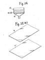
- This electrode for the methanol fuel cell has a problem that carbon dioxide bubbles 1 produced as-one of the reaction products cover the surface of catalysts 2 to result in a lowering of effectiveness of the catalysts and of electrode characteristics.
- the main use of the methanol fuel cell is considered to be a transportable or mobile electric source, and the circulation of the strongly corrosive electrolyte is dangerous and may lead to the corrosion of the equipment employed. Moreover the corroded product may bring about the poisoning of the catalysts. Purification of electrolyte and water is further required to prevent the poisoning of the catalysts.
- the present invention is to overcome the above disadvantages.
- An object of the invention is to provide a gas permeable electrode without the lowering of the effectiveness of catalysts due to product bubbles such as carbon dioxide.
- Another object of the invention is to provide a gas permeable electrode employing no corrosive electrolyte.
- a further object of the invention is to provide a gas permeable electrode requiring no purification of water and fuel employed.
- a gas permeable electrode according to the present invention comprises a gas permeable layer comprising hydrophobic resins and an electrically conductive porous body or electrically conductive fine powders, and a reaction layer comprising a semi-hydrophobic porous body prepared by the coagulation of hydrophobic portions and hydrophilic portions, the both layers being attached to each other, the electrolyte impregnating the hydrophilic portion of the reaction layer to be held therein, and the hydrophobic portions thereof constituting gas passages.
- electrolyte penetrates into the reaction layer and does not penetrate into the gas permeable layer, and only the gas produced on the electrode and the gas supplied penetrate into the gas permeable layer.
- the reaction layer of the electrode comprises a semi-hydrophobic porous body which may contain an electrically conductive porous body or fine particles and hydrophobic resins impregnated or dispersed to be mixed therein, which is then thermally treated.
- This reaction layer can be replaced by another semi-hydrophobic body manufactured by mixing fine particles supported with catalysts and fine particles with no catalyst imparted of hydrophobic property by adding hydrophobic resins.
- the above electrically conductive porous body or fine particles may be hydrophilic or hydrophobic carbon blacks or the like, and the above hydrophobic resins may be polytetrafluoroethylene (hereinafter referred to as PTFE) or other fluorinated resins or the like.
- the above catalysts may contain platinum group metals such as platinum, palladium, rhodium, ruthen ⁇ ium etc., gold, siver, iron, nickel and cobalt and/or their oxides or alloys, activated carbon and the like.
- the carbon blacks and/or the catalysts serve as electrode active components.
- the proportion of the hydrophobic resins to the reaction layer is preferably in the range of 8 : 2 to 2 : 8, most preferably 3 : 7.
- the gas permeable layer ideally has perfect hydrophobic property and high gas permeability. In case of the combination of the PTFE powders and the carbon blacks, its ratio is preferably 6 : 4.
- the above reaction layer which contains the catalysts is made by depositing the catalysts to the fine particles which can be hydrophilic carbon blacks and mixing them with fluorinated carbon such as PTFE to be bound with each other, the reaction layer does not always provide the structure which allows the electrolyte to penetrate to the catalyst portions and which has the cataiyst portions to which the electrolyte penetrates and the gas permeation passages, both of which are uniformly and finely dispersed. Therefore, some of the catalysts in the reaction layer is not in contact with the electrolyte so that it does not contribute to the reaction, and the contact area between the electrolyte and the gas permeation passages is insufficient so that it lowers the catalyst performance.
- a plurality of the thinly formed hydrophilic portions containing the catalysts and the same number of the thinly formed water-repellent portions can be superimposed alternatively to constitute the reaction layer.
- a plurality of the ultra thinly formed hydrophilic portions and the same number of the ultra- thinly formed hydrophobic portions are superposed alternatively to form a powder, and a plenty of the said powders can be coagulated to constitute a reaction layer shaped as a sheet.
- mixed portions whose property is intermediate between those of the hydrophilic portions and the hydrophobic portions in the above instances can be interposed therebetween.
- the following means can be employed. At first, a plenty of fine fiber-like hydrophilic portions and/or hydrophobic portions which are oriented towards the thickness of the sheet and of which both ends are exposed to the both sides are randomly dispersed in the sheet to form a reaction layer. Secondly, powders each comprising the fiber-like hydrophilic portions and the hydrophobic portions are coagulated to form a reaction layer.
- the catalysts supported in the hydrophilic portions of the reaction layer do not firmly adhere to the fine particles, they may be dissolved out by exposure to electrolyte during the use in a secondary batterry or the like, or may be moved to be coagulated with the rise of temperature.
- the catalyst activity of the hydrophilic portions may be thus lowered, and the charging rate and the discharging rate may be lowered to shorten the life.
- the following means can be employed. Ion exchange resin is penetrated to the hydrophilic portions in addition to the catalysts supported therein to form a reaction layer comprising a hydrophilic layer and a hydrophobic layer.
- the gas permeable layer comprises a highly hydrophobic porous body which contains an electro-conductive porous body or fine particles and hydrophobic resins impregnated or dispersed to be mixed therein, which is then thermally treated.
- This high hydrophobic property can be obtained by increasing the volume of the resins in the gas permeable layer or by adding such hydrophobic reinforcing agents as wax, fluorinated graphite and the like.
- the reaction layer and the gas permeable layer are attached to each other by a conventional press-molding or hot-pressing to constitute the gas permeable electrode. Since the thus manufactured electrode is very thin, it is insufficient in strength and readily bent or warped so that deformation or crack may occur. When the crack develops in the gas permeable layer, electrolyte passes through the layer along the crack to lose the gas permeable layer the hydrophobic property.
- a reinforcing sheet e.g. a non-woven fabric sheet.
- the non-woven fabric sheet is preferably a heat resistant fabric which is made of carbon fiber, nickel fiber, stainless steel fiber, aramide fiber, silicon carbide fiber or the like.
- the non-woven farbic sheet may be incorporated in the reaction layer and/or the hydrophobic layer.
- One of the general manufacturing processes of the gas permeable ,electrode containing the catalysts is such as follows.
- the mixed suspension of platinum powders, carbon blacks, water and PTFE powders is filtered to be made to a first cake, and another mixed suspension of hydrophobic carbon blacks, water and PTFE powders is filtered to be made to a second cake.
- the both layers are cut to a desired demension and then attached to each other by heat-pressing Since, however, the platinum powders of the gas permeable electrode obtained according to the above manufacturing process may be mainly present among the carbon blacks and the PTFE powders which are hydrophobic or among the PTFE'powders, electrolyte is not in contact with all the platinum particles, even though it penetrates to the reactionlayer. It is also difficult in the above process to roll-mold the both layers, and further since the scrap containing the platinum is produced in cutting them to the desired dimension, labor and expense are requiredto recover it.
- the catalysts may be incorporated into the reaction layer after the both layers are attached to each other.
- One of the examples of this process is such as follows.
- the mixed suspension of hydrophilic and hydrophobic carbon blacks, water (or such solvent as alcohol) and PTFE powders is filtered to be made to a first cake, and another mixed suspension of hydrophobic carbon blacks, water (or such solvent as alcohol) and PTFE powders is filtered to be made to a second cake.
- the both cakes are penetrated with a solvent, the both are rolled to respective desired thicknesses. Then, after they are individually heated to remove the water and the solvent to form the two sheets, the both sheets are attached to each other by heat and pressure.
- the sheet including the hydrophilic carbon blacks is then impregnated with a solution of a platinum group metal compound which is then decomposed by heat so that the platinum group metal and/or its oxides adhere to the hydrophilic portions of the react ion layer to provide the gas permeable electrode having the reaction layer comprising the hydrophilic portions and the hydrophobic portions, and the hydrophobic gas permeable layer.
- the said process may be modified as described earlier by alternatively superimposing a plurality of the reaction layers and a plurality of the gas permeable layers and/or by incorporating, for example, the non-woven fablic sheet for reinforcement in the reaction layer and/or the gas permeable layers.
- the gas permeable electrode having the reaction layer manufactured by the usual process which comprises mixing and pressing electrically conductive fine particles to which catalysts may adhere and hydrophobic fine powders and then sintering them to form the reaction layer
- the electrically conductive fine particles and the hydrophobic powders arc not sintered as desired by pressing and are relaxed in high temperature by thermal expansion of the powders. Therefore, many electrolyte passages and gas passages may be disconnected to interrupt the contact of the electrolyte with the catalyst in the reaction layer.
- a process which comprises mixing and hot-pressing electrically conductive fine particles and a binding agent, and cooling them under the hot-pressing condition or immediately thereafter to form a reaction layer.
- the powers are firmly held not to be moved. Since, moreover, the powders are cooled immediately after or during the hot-pressing, the powder condition at the time of the sintering is maintained to provide the electrolyte penetration passages and gas permeation passages with no disconnection as expected.
- the gas permeable electrode of the present invention can generally be manufactured by employing the pressing technique, which may comprise flatly disposing the component particles on a press plate and then hot-pressing them to form the reaction layer.
- the pressing technique which may comprise flatly disposing the component particles on a press plate and then hot-pressing them to form the reaction layer.
- the component particles cannnot be disposed evenly on the press plate, - the resulting layer inherently accompanies the uneven densities not to form the uniformly dispersed passages for contacting the gas and the electrolyte.
- the operation efficiency of this process is also insufficient because the particles should be flatly disposed on the press plate having a relatively large area.
- the component particles having been mixed and stirred are poured into a cistern of which the bottom is attached to a sheet, to float on the surface. Then the water is removed through the sheet so that the particles deposit to and accumulate on the sheet. Then the sheet is dried and hot-pressed to form a reaction layer.
- the gas permeable electrode according to the present invention can be applied to a wide range of usages such as a methanol fuel cell, organic electrolysis, a secondary battery, an electrochemical reactor, galvanization, and the like.
- such gases as carbon dioxide produced as one of the reaction products in the reaction layer permeate to the hydrophobic fine apertures of the gas permeable layer before the supersaturation thereof in electrolyte forming gas bubbles to reach the rear side of the electrode to be released therefrom. Therefore, the surface of the reaction layer is never covered by the gases. The catalyst efficiency and the electrode characteristics are never lowered. Moreover, the purification of water and fuel is unnecessary.
- Fig. 2 (a) is a schematic cross sectional view of a first embodiment of a gas permeable electrode according to the present invention applied to a methanol fuel cell
- Fig. 2 (b) is an enlarged view of the portion indicated by A in Fig. 2 (a).
- a reaction layer comprises a semi-hydrophobic porous body 3 prepared by impregnating water-repellent resin to an electrically conductive porous body or electrically conductive fine particles supported with catalysts 2, or by mixing and dispersing them, which is then thermally treated.
- a gas permeable layer comprises a highly hydrophobic porous body 4 prepared by impregnating hydrophobic resins to an electrically conductive porous body or fine particles, or by mixing and dispersing them, which is then thermally treated.
- methanol which serves as fuel is merely dissolved in water to be supplied to the surface of the reaction layer for circulation.
- the methanol passes through the hydrophobic layer in the form of vapor, and further passes through the hydrophobic portions of the reaction layer to be dissolved into the electrolyte present near the catalysts. It is oxidized on the nearby catalysts, and the carbon dioxide produced is dissolved into the electrolyte.
- the carbon dioxide produced evaporates into the hydrophobic fine apertures before the supersaturation thereof in the electrolyte forming gas bubbles to reach the rear side of the electrode through the passages in the reverse direction of the methanol passages, and is released as gas bubbles into water.
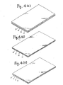
- Fig. 3 is a perspective view of a second embodiment of a gas permeable electrode according to the present invention.
- Figs. 4 (a) to (i) show a series of manufacturing steps of the electrode of Fig. 3.
- a gas permeable electrode 5 shown in Fig. 3 comprises a reaction layer 6 and a gas permeable layer 7.
- the reaction layer 6 comprises respective 10 5 sheets of hydrophilic portions 8 and of hydrophobic portions 9 superimposed alternatively.
- the hydrophobic gas permeable layer 7 having 110 mm of width, 110 mm of length and 0.5 mm of thickness comprises hydrophobic carbon blacks having 420A of the mean particle size and PTFE powders having 0.3 u of the mean particle size in the proportion of 6.5 : 3.5.
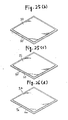
- the electrode 5 having the above structure can be manufactured by the following procedures.
- a first sheet 10 and a second sheet 11 are superimposed to be rolled to a composite sheet having 2 mm of thickness (Fig. 4 (b)).
- the first sheet 10 having 100 mm of width, 3 m of length and 2 mm of thickness is formed by mixing hydrophilic carbon blacks having 450 A of the mean particle size and PTFE powders having 0.3 ⁇ of the mean particle size in the proportion of 7 : 3, and further mixing solvent naphtha thereto in the proportion of 1 : 1.8 and then molding it.
- the second sheet 11 having 100 mm of width, 3 m of length and 2 mm of thickness is formed by mixing hydrophobic carbon blacks having 420 A of the mean particle size and PTFE powders having 0.3 ⁇ of the mean particle size in the proportion of 7 : 3, and further mixing solvent naphtha thereto in the proportion of 1 : 1.8 and then molding it.
- the above composite sheet is then cut into two sheets and the two sheets are superimposed as shown in Fig. 4(c) to be rolled to another composite sheet having 2 mm of thickness (Fig. 4 (d)).
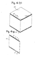
- the sheet is cut by every 100 mm of length and the fifty sheets are superimposed and compressed to make a block 12 shown in Fig. 4 (f).
- the sliced sheets are heated up to 280 °C to remove the solvent naphtha, thus forming a reaction layer raw material sheet 13 having 100 mm of width and 100 mm of length and having the hydrophilic portions and the hydrophobic portions superimposed alternatively and in parallel as shown in Fig. 4 (g).
- the hydrophilic portions 8 and the hydrophobic portions 9 are in the form of fibers.
- the hydrophobic gas permeable layer 7 which has 110 mm of width, 110 mm of length and 0.5 mmof thickness and which has been prepared by the molding of the mixture of hydrophobic carbon blacks having 420 A of the mean particle size and PTFE powders having 0.3 u of the mean particle size at 380 C and600 kg/cm 2 for three seconds as shown in Fig. 4 (h). Then, as shown in Fig.
- the solution of chloroplatinic acid is applied to the surface of the reaction layer raw material sheet 13 to impregnate itself to the hydrophilic portions 8, and the sheet 13 is heated at 200 'C for 60 minutes to decompose the chloroplatinic acid, and further heated in the hydrogen atmosphere at 200 °C for one hour to attach the platinum to the hydrophilic portions 8, thus making the sheet 13 into the reaction layer 6.
- the electrolyte does not penetrate to the hydrophobic portions 9 of the reaction layer 6, but penetrates only to the hydrophilic portions 8 having the platinum catalysts to be in contact with most of the platinum catalysts. Therefore, the most of the platinum catalysts in the reaction layer 6 contribute to the catalytic reactions.
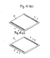
- Fig. 5 is a perspective view of a third embodiment of a gas permeable electrode according to the present invention.
- Figs. 6 (a) to (d) show a series of manufacturing steps of the electrode of Fig. 5.
- the third - embodiment is a modification of the second embodiment.
- a gas permeable electrode 5a of the present embodiment comprises, as shown in Fig. 5, hydrophilic portions 8a and hydrophobic portions 9a alternatively superimposed in the direction of the radius, which are spirally wound.
- a plenty of sheets are thinly rolled, as shown in Fig. 4 (a) of the above embodiment, and then spirally wound and compressed with each other to make a cylindrical block 12a having a plenty of layers as shown in Fig. 6 (a).
- the sliced sheets are heated up to 280 * c to remove the solvent naphtha, thus forming a reaction layer raw material sheet 13a having the hydrophilic portions 8a and the hydrophobic portions 9a super- imposed alternatively in the direction of the radius, as shown in Fig.6(b).
- reaction layer raw material sheet 13a is then thermally attached the circular and hydrophobic gas permeable layer 7a prepared by the molding of hydrophobic carbon blacks and PTFE powders as shown in'Fig. 6 (c). Then, as shown in Fig. 6 (d), the solution of chloroplatinic acid is applied to the surface of the reaction layer raw material sheet 13a to impregnate itself to the hydrophilic portions 8a, and the sheet 13a is heated as indicated in the second embodiment to decompose the chloroplatinic acid, and further heated to attach the platinum to the hydrophilic portions 8a. thus making the sheet 13a into the reaction layer 6a.
- the electrolyte does not penetrate to the hydrophobic portions 9a of the reaction layer 6a, but penetrates only to the hydrophilic portions 8a having the platinum catalysts to be in contact with most of the platinum catalyst. The most of the platinum catalysts in the reaction layer 6a therefore contribute to the catalytic reactions.
- an eleclricity collecting member may be attached to the gas permeable layer.
- solvent naphtha is employed as solvent in the embodiment, the present invention is not limited to this solvent. Water and such alcohols as ethanol, iso-propyl alcohol and the like, and such hydrocarbons as n-butane may be employed.
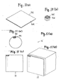
- Fig. 7 is an enlarged cross sectional view of a fourth embodiment of a gas permeable electrode according to the present invention.
- Figs. 8 (a) and (b) show manufacturing steps of the electrode of Fig. 7. This embodiment is a modification of the second embodiment.
- a gas permeable electrode 5b of the present embodiment comprises, as shown in Fig. 7, hydrophlic portions 8b which comprise platinum powders, hydrophillic carbon blacks and PTFE powders, and the hydrophobic portions 9b, both of which are alternatively superimposed to be molded to a reaction layer 6b in the shape of a sheet.
- Such a gas permeable electrode 5b is manufactured according to the following procedures.
- the composite sheet of the second embodiment shown in Fig. 4 (e) is prepared by the same procedures of the second embodiment.
- the powders 14 are mixed with solvent naphtha in the proportion of 1 : 1.8 to be roll-molded to form a raw material sheet 13b as shown in Fig. 8 (b).
- the sheet 13b is made to the gas permeable electrode 5b by the same procedures descrided in the second embodiment.
- the thus manufactured electrode exhibits the catalytic characteristics superior to those of the preceding embodiments.
- Fig. 9 is an enlarged cross-sectional view of a fifth embodiment of a gas permeable electrode according to the present invention. This embodiment is a modification of the second embodiment.
- a reaction layer 6c of a gas permeable electrode 5c shown in Fig. 9 having 100 mm of width, 100 mm of length and 0.1 mm of thickness comprises hydrophilic portions 8c, hydrophobic portions 9c and mixed portions 15, the hydrophilic portions 8c and the hydrophobic portions 9c, the total number of which amounts to 2.5 X 10 4 , being alternatively super-imposed with the mixed portions 15 intervening therebetween.
- the hydrophilic portions 8c having 1 ⁇ of width, 100 mm of length and 0.1 mm of height comprise platinum particles having 50 A of the mean particle size, hydrophilic carbon blacks having 450 A of the mean particle size and PTFE powders having 0.3 ⁇ of the mean particle size in the proportion of 0 .7 : 7 : 3.
- the hydrophobic portions 9c having 1 ⁇ of width, 100mm of length and 0.1 mm of height comprise hydrophobic carbon blacks having 420 A of the mean particle size and PTFE powders having 0.3 ⁇ of the mean particle size in the proportion of 7 : 3.
- the mixed portions 15 having 1 ⁇ of width, 100 mm of length and 0.1 mm of height comprise platinum particles having 50A of the mean particle size, hydrophilic carbon blacks having 450A of the mean particle size, hydrophobic carbon blacks having 450 A of the mean particle size and PTFE powders having 0.3 u of the mean particle size in the proportion of 0.7 : 7 : 3 : 3.
- the reaction layer 6c can be manufactured by employing a hydrophilic sheet, a hydrophobic sheet and a mixed sheet, and by employing similar procedures described in the second embodiment or the third embodiment.
- reaction layer 6c comprises the hydrophilic portions 8c and the hydrophobic portions 9c alternatively superimposed, and the mixed portions intervened therebetween, electrolyte penetrates to all of the hydrophilic portions and to the hydrophillic portions of the mixed portions to be in contact with most of the platinum catalysts and to strikingly enlarge the contact areas of the electrolyte with the gas permeable passages. A large quantity of electricity can, therefore, be flown in the electrode of this embodiment.
- Fig. 10 (a) is a perspective view of a sixth embodiment of a gas permeable electrode according to the present invention, and Fig. 10 (b) is an enlarged view thereof.
- Figs. 11 (a) to (d) show manufacturing steps of the electrode of Fig. 10 (a).
- a reaction layer 6d of a gas permeable electrode 5d shown in Figs. 10 (a) and (b) comprises hydrophilic portions 8d and hydrophobic portions 9d which are randomly dispersed in the direction of the thicknessof a sheet and in the form of fibers and which have 2 g of the mean thickness and the both ends of which are exposed to the both sides.
- the hydrophylic portions 8d comprise hydrophillic carbon blacks and PTFE powders
- the hydrophobic portions 9d comprise hydrophobic carbon blacks and PTFE powders.
- Such a gas permeable electrode 5d is manufactured according to the following procedures. After the mixture of the hydrophillic carbon blacks, the PTFE powders and water in the proportion of 7.5 : 2.5 : 40 having the ductility is prepared, the mixture is extruded to form 500 pieces of hydrophilic wire rods having 1 mm of the wire diameter. In a similar way, 500 pieces of hydrophobic wire rods comprising hydrophobic carbon blacks, PTFE particles and water are prepared. Then, the 500 pieces of the hydrophillic wire rods and the 500 pieces of hydrophobic wire rods are bundled in the well-dispersed state as shown in Fig. 11 (a).
- the wire rods 16 for the reaction layer having 1 mm of the wire diameter as shown in Fig. 11 (b).
- About 1200 pieces of the wire rods 16 for the reaction layer are, as shown in Fig. 11 (c), bundled and compressed to form a rod material 17 for the reaction layer having the rectangular cross section which is 100 mm long and 100 mm broad.
- the rod material 17 for the reaction layer is sliced,'as shown in Fig. 11 (d), by every 0.2 mm of thickness to form a reaction layer raw material 18.
- the reaction layer raw material 18 is thermally dried at 280 'C for 180 minutes to remove the water serving as solvent to form the gas permeable electrode 5d containing the reaction layer 6d shown in Figs. 10 (a) and (b).
- composite wire rods may be employed which are composed of, for instance, hydrophillic core rods covered with hydrophobic wire materials.
- the hydrophilic portions and the hydrophobic portions are randomly dispersed in the direction of the thickness of a sheet and in the form of fibers, the electrolyte penetration passage areas and the gas permeation passage areas are considerably large. The contact areas of the electrolyte and the gas is increased to promote reactions.
- Fig. 12 (a) is a cross sectional view of a gas permeable electrode of the seventh embodiment of the present invention.
- Fig. 12 (b) is a partially enlarged schematic view thereof.
- Fig. 13 is a partially enlarged schematic view of the electrode applied to a hydrogen oxygen fuel cell.
- a gas permeable electrode 5f comprises a reaction layer 6f and a gas permeable layer 7f attached to each other.
- the reaction layer 6f comprises a sheet 19 having 0.1 mm of thickness, 100 mm of width and 100 mm of length and comprising hydrophilic carbon blacks, hydrophobic carbon blacks and PTFE powders in the proportion of 4 : 3 : 3.
- On the hydrophilic carbon blacks of the sheet is supported 0.056 g of platinum catalysts. Ion exchange resin is penetrated only to the hydrophilic portions of the sheet 19 to form an ion exchange resin film 20.
- the platinum catalysts are fixed by the ion exchange resin.
- the gas permeable layer 7f comprises a sheet having 0.5 mm of thickness, 120 mm of width and 120 mm of length and comprising hydrophobic carbon blacks and PTFE powders in the proportion of 7 : 3 .
- hydrophilic portions 8f comprise the hydrophilic carbon blacks, the PTFE powders, the platinum catalysts and the ion exchange resin, and hydrophobic portions 9f comprise the hydrophobic carbon blacks and the PTFE powders.
- two sheets of the gas permeable electrodes 5f are superimposed with the ion exchange resin films 20 adjoining each other and are employed as a counter electrode of hydrogen-oxygen fuel cell.
- H z is supplied from the gas permeable layer side 7f of one of the gas permeable electrodes 5f (negative pole side) and O z is supplied from the gas permeable layer side 7f of the other gas permeable electrode 5f (positive pole side)
- the H 2 having entered into the gas permeable layer 7f of the former gas permeable electrode 5f permeates the hydrophobic portions 9f of the reaction layer 6f to reach the boundary with the hydrophilic portions to be made hydrogen ions at this point by the catalytic reaction of 112 ⁇ 2H + + 2e - .
- the II - migrates from the hydrophilic portions 8f into the ion exchange resin film 20 (cation exchange resin in this case), the e - flows to the positive pole side through an external lead 21.
- the 0 z having entered into the gas permeable layer 7f of the latter gas permeable electrode 5f permeates the hydrophobic portions 9f of the reaction layer 6f to reach the boundary with the hydrophilic portions to be made oxygen ions by the catalytic reaction of 1 ⁇ 2O 2 + 2e ⁇ O 2- with the 2e - flown from the negative pole side.
- the 0 2- reacts with the H having migrated in the ion exchange resin film 20 to be converted into water by the reaction of 0 2- + 2H + - H z O.
- the H 2 O is then vaporized to inversely permeate the gas permeable layer 7f to be discharged to the exterior. Since 2e - are always released at the negative pole side to flow from the positive pole side to the negative pole side through the external lead, the electricity can be effectively taken out.
- the ion exchange resin film separates the methanol and hydrogen ion to prevent the electrode exhaustion due to oxidation.
- the mixed solution of liquid Nafion (trade name), ethanol and water may be applied to a face of the sheet 19 and vacuum-sucked from the opposite face.
- the catalysts supported on the hydrophilic portions of the reaction layer are fixed by the ion exchange resin, they are never exposed to electrolyte.
- the flowing-away of the catalysts and the migration or the coagulation of the catalysts in the elevated temperature and the lowering of the catalytic activity of the hydrophillic portions never occur.
- the efficiencies of charge and discharge are high and a large quantity of electricity can be easily taken out and the life is long. Since evaporation in water of the electrolyte can be avoided, less water supplement is required.
- Fig. 14 is a cross sectional view of an eighth embodiment of the present invention which is a process for manufacturing copper foils by employing one of the gas permeable electrodes of the present invention.
- a gas permeable electrode 5g comprising a reaction layer 6g comprising finely divided hydrophilic portions supported with Pt (which may be replaced with Pt-Ru) catalysts and finely divided hydrophobic portions, and a hydrophobic gas permeable layer 7g, both layers being attached to each other is positioned at the bottom of the cell 22 as a semi-cylindrical positive pole opposing the rotating negative pole 23.
- the cell 22 is filled with a copper-galvanization solution 24 so that the top of the gas permeable electrode 5g is located below the surface of the copper-galvanization solution 24 and methanol is supplied to the solution 24, electrolysis is carried out forming a copper foil 25 on the lower semicircumference of the rotating negative pole 23.
- the copper foil 25 thus produced is rolled to a reel (not shown) by rotating the negative pole 23 and pulling up the copper foil 25.
- the methanol in the copper-galvanization solution 24 is decomposed in the hydrophillic portions of the reaction layer Gg of the gas permeable electrode 5g to generate COz which is absorbed into the hydrophobic portions of the reaction layer 6g to permeate the gas permeable layer 7g.
- the copper-galvanization solution 24 containing the methanol lowers the bath potential, and the decomposition (combustion) of the methanol lowers the power consumption. These can make the intelectrode distance less and the current density larger. Further, the lowering of the bath voltage and no generation of O z result in no oxidation of the electrode as well as of the copper foil so that the cell life of the present embodiment can be extended to several thousands hours while the life of a conventional cell is several hundreds hours.
- Figs. 15 to 17 are cross sectional views of a ninth embodiment of the present invention which show a series of the manufacturing process of a gas permeable electrode.
- the filter paper 29 with the accumulated mixed particles 26 is heated with a heater to completely remove the water. Thereafter, the mixed particles 26 on the filter paper 29 is, as shown in Fig. 17, bound together by hot-pressing to produce a reaction layer 6h having 0.15 mm of thickness, 100 mm of length and 100 mm of width.
- reaction layers 6h of one hundred sheets are examined by an optical microscope to find that most of them have no unevenness and that the passages for the contact between gas and electrolyte are uniformly and finely dispersed.
- reaction layer 6h is then stripped from the filter paper 29 and attached to a hydrophobic gas permeable layer to form a gas permeable electrode having a plurality of the layers.
- catalyst particles as Pt, Ir, Au, Ag, IrO z , RuO z , Pd0 particles may be supported therein.
- the procedure of the present embodiment may be applied to a gas permeable layer of an electrode other than the reaction layer.
- Fig. 18 is a schematic cross sectional view of a tenth embodiment of the present invention which is a manufacturing process of a reaction - sheet or a gas permeable sheet for a gas permeable electrode.
- the tenth embodiment is a modification of the ninth embodiment.
- the mixture which is same as that for the ninth embodiment is, as shown in Fig. 18, poured onto water 27' of a cistern 28'.
- a tetronic screen 32 wound on a sheet winding roll 33 equipped on one inner side of the cistern 28' is drew out to be pulled up slopewise toward the other side of the cistern 28' with a particles compressing plate 34 simultaneously moving at the same rate so that the mixed particles 26' floating on the water 27' are deposited on the tetronic screen 32 which is then passed through a pair of guide rolls 35 to press the mixed particles 26' for the particle-binding and dehydration.
- the sheet-like mixed particles having been separated from the sheet 32 and cut to a desired length are bound together by hot-pressing to prepare belt-like reaction films having 0.15 mm of thickness.
- the structure of the 100 reaction films thus prepared are examined by an optical microscope to find that most of them have no unevenness and that the passages for the contact between gas and electrolyte are uniformly and finely dispersed.
- Fig. 19 is a cross sectional view of an eleventh embodiment of a gas permeable according to the present invention.
- Figs. 20 (a) to (d) are a series of manufacturing procedures thereof.
- a gas permeable electrode 5i shown in Fig. 19 comprises a reaction layer 6i having 0.1 mm of thickness and 65 % of porosity and a gas permeable layer 7i having 0.5 mm of thickness and 65 % of porosity both of which are attached to each other.
- the reaction layer 6i comprises a non-woven fabric sheet 37 of carbon paper having 280 ⁇ of thickness made of fibers of 7 ⁇ which is impregnated and deposited with the mixture of platinum serving as catalyst, hydrophobic carbon blacks, hydriphillic carbon blacks and PTFE powders in the proportion of 1 : 5 : 5 : 3.
- the gas permeable layer 7i is formed by molding the mixture of carbon blacks and PTFE powders..
- the hydrophobic gas permeable layer 7i formed by molding the mixture of hydrophobic carbon blacks and PTFE powders is then thermally attached under pressure of 600 kg/cm z for three seconds at 380 'C to the above reaction layer raw material sheet 38 as shown in Fig. 20 (c).
- a chloroplatinic acid solution is applied to and impregnated into the reaction layer raw material sheet 38, and then it is decomposed by heatingto 200°C, reduced in H 2 at 200 °C and deposited by 0.56 mg/cm z to prepare the reaction layer of 65 % porosity to produce the gas permeable electrode 5i shown in Fig. 20 (d).
- the gas permeable electrode 5i of this embodiment contains the non-woven fabric sheet 37 in its reaction layer 6i, it is hard to be bent and warped and the flexural strength thereof is high. It is therefore never deformed or cracked in handling.
- the non-woven sheet may be incorporated in the reaction layer and/ or the gas permeable layer.
- Fig. 21 is a partially omitted perspective view of a twelfth embodiment of a gas permeable electrode according to the present invention.
- Fig. 22 is an enlarged cross-sectional view of a wire rod.
- a gas permeable electrode shown in Fig. 21 comprises a reaction layer 6j and a gas permeable layer 7j which are attached to each other.
- the reaction layer 6j having 0.1 mm of thickness comprises catalysts (R U 0 2 + IrO z ), hydrophobic carbon blacks and PTFE powders in the proportion of 3 : 3 : 2 and contains finely divided hydrophillic portions and hydrophobic portions.
- the gas permeable layer 7j having 0.5 mm of thickness comprises hydrophobic carbon blacks and PTFE powders in the proportionof 7 : 3.
- a collecting member 39 formed by networks of wire rods 40 with 0.5 mm of spacings, each of which is a Ti wire 41 of 0.3 mm size coated with Pt 42 of 5p thickness as shown in Fig. 22.
- the Ti wires may be replaced with Ta wires, or Ti- or Ta-coated Cu wires and the Pt coating may be replaced with other platinum group metals and/or metal oxides' coating.
- the above collecting member 39 may be embedded in the gas permeable layer 7j.
- the collecting member comprises the networks or the like of the wire rods made of the Ti or Ta, or the Ti- or Ta-coated Cu with the contacting portions to the gas permeable layer being coated with the platinum group metals and/or its oxides, the collecting member having the acid-proof is never corroded, even though an acid is produced at the collecting member's side of the gas permeable layer. Further, the electrode has a small electrical resistance and a high collected current.
- fig. 23 is a vertical sectional view of an apparatus for water electrolysis equipped with a thirteenth embodiment of a gas permeable electrode of the presentinvention.
- a gas permeable electrode 5k which comprises a reaction layer 6k and a gas permeable layer 7k attached to each other, is employed as positive pole in an electrolytic cell 43.
- 44 denotes a cathode which is the same electrode as the positive pole, and 45 denotes electrolyte which is a KOH aqueous solution in this embodiment.
- the spaces outside the respective gas permeable electrodes 7k of the both poles are filled with water 46.
- electrolysis is carried out at a high current density condition, for instance at 1 A/cm z
- the KOH aqueous solution 45 impregnated in the reaction layers 6k of the both poles generates O z gas which disperses and permeates into the gas permeable layer 7k to be released to the exterior through the water.
- the tempratures of the both poles 5k, 44 rise due to the high current density to vaporize the water of the KOH aqueous solution in the reaction layer 6k, which after having been saturated are released to the gas permeable layers 7k.
- Figs. 24 and 25 show a fourteen embodiment of of the invention.
- Fig. 24 is a cross sectional view of a filtering device employed in this embodiment, and
- Figs. 25 (a) to (d) show a series of procedures for manufacturing a gas permeable electrode of this embodiment.
- hydrophobic carbon blacks in the proportion of 1 : 1
- water hydrophobic carbon blacks (in the proportion of 1 : 1) and water are mixed and stirred in a colloid mill at 50 °C
- PTFE powders are added to the mixed solution in the proportion of 2 : 8 to the carbon blacks and mixed and stirred.
- the mixed solution is then charged to a filtering device 47 to be filtered to form a cake 48 on a filtering sheet 40 as shown in fig. 24.
- PTFE powders are added to the mixed solution in the proportion of 7 : 3 to the carbon blacks and mixed and stirred.
- the mixed solution is then charged to the filtering device 47 to be filtered to form another cake 48' on the filtering sheet by a similar procedure to that shown in Fig. 24.
- the cakes 48, 48' are then penetrated with such a solvent as ethanol, butanol, iso-propyl alcohol, an ammonium carbonate solution, an ammonium hydrocarbonate solution, solvent naphtha, acetone or the like, to be rolled to the respective thicknesses of 0.1 mm and 0.5 mm.
- the both cakes are then heated at 280'C to be dried and to remove the ethanol to form two sheets 50, 50'.
- both sheets 50, 50' are cut 100 mm by 100mm and 110 mm by 110mm respectively, they are attached to each other at 380'C and 600 kg/cm z as shown in Fig. 25 (b).
- a palladium chloride solution 51 is applied to and impregnated into the surface of the sheet 50 containing the hydrophilic carbon blacks as shown in Fig. 25 (c)
- the solution is thermally decomposed at 200°C in air and reduced in H 2 to deposit palladium on the hydrophilic carbon blacks so that a gas permeable electrode 5m having a reaction layer 6m comprising hydrophilic portions and hydrophobic portions, and a hydrophobic gas permeable layer 7m is prepared, as shown in Fig. 25 (d).
- Figs. 26 and 27 show a fifteenth embodiment of the present invention, which relates to a process for supporting catalyst particles.
- Fig. 26 is an enlarged cross-sectional view of catalyst particles prepared according to a conventional process.
- Fig. 27 is a corresponding enlarged cross-sectional view of the catalyst particles prepared according to the present embodiment.
- the size of electrically conductive particles 51 is 0.01- 0.06 ⁇ which is one order smaller than the minor axis of hydrophobic resins 53, the electrically conductive particles 51 are aggregated to form an electrically conductive particles cluster 55. Since the electrically conductive particles cluster 55 is hydrophilic to the electrolyte, the electrolyte penetrates to the cluster.
- the electrically conductive particles 51 on the surface of the hydrophobic resins 53 together with the electrically conductive particles 51 of the opposing electrically conductive particles cluster 55 form, on the other hand, gas supply passages.
- the sufficient volume of gas for the catalytic reaction of the electrically conductive particles cluster 55 can be supplied because the gas supply passages are located at the vicinity of the electrically conductive particles cluster 55.
- the electrical conductive particles cluster 55 are preferably connected just like skeltons for the penetration of the electrolyte to the whole catalytic layer-.
- the gas permeable electrode of Fig. 2 was employed for a methanol fuel cell which comprised a gas permeable layer comprising PTFE powders and carbon blacks (6:4) and having a copper-mesh compressed and attached thereto as electrically conductive material for collecting electricity, and a reaction layer comprising electrically conductive fine particles supported with binary catalysts (platinum 2 mg and ruthenium 1 mg per cm 2 ) and bound together with a hydrophobic binding agent.
- binary catalysts platinum 2 mg and ruthenium 1 mg per cm 2
- the both layers were attached to each other by press-molding, and sulfuric acid electrolyte (concentration: 2 mol) was impregnated and held in the hydrophilic portion of the reaction layer.
- Methanol was dissolved in water (concentration: 2 mol) and supplied to the hydrophobic surface to be circulated.
- the current density was 200 mA/cm 2 at 60°C and 0.4 V, and the limiting current was 1200 mA/cmz.
- the current density was 40 mA/cm 2 at 60°C and 0.4 V, and the limiting current was 300 mA/cm 2 .
- the mixed particles composed of the same electrically conductive fine particles having the same supported quantities of the same catalysts as described above, and the hydrophobically treated carbon blacks were press-molded to form the reaction layer.
- the characteristic was further advanced to obtain the characteristic of 260 mA/cm 2 at 60°C and 0.4 V.
- Example 2 The same electrode of Example 1 was used as that for lowering the voltage of the zinc electrolyzing bath.
- the electrolysis was carried out at 27 °C and at 3 mm of the interelectrode distance employing the zinc electrolyte containing 60 g of Zn and 270 g of H 2 SO 4 per liter.
- the bath voltage obtained were 1.5 V a 0.5 A/cm 2 and 2.0 V at 1 A/cm 2 .
- the electrode of this Example can reduce the bath voltage by half, and can increase Lhc current density (production rate) by a factor of 10 to enable the striking power saving and rapid production.
- An electrolytic cell was charged with 0.1 liter of a 0.5 M solution of pottasium hydrogen carbonate (KHCO 3 ).
- KHCO 3 pottasium hydrogen carbonate
- a Pt mesh and an ion exchange membrane (Nafion 117) were employed as a positive pole and a diaphram respectively.
- a gas permeable electrode comprising a reaction layer comprising finely divided hydrophillic portions and hydrophobic portions and a gas permeable layer, both layers being attached to each other, was employed as an electrolytic reduction electrode (negative pole).
- the reaction layer having 0.1 mm of thickness, 100 mm of wigth and 100 mm of h'eight was formed by molding the mixture of lead blacks (420A of mean particle size), hydrophobic carbon blacks (420 A of mean particle size) and PTFE particles (0.3 ⁇ of mean particle size).
- the gas permeable layer having 0.4 mm of thickness, 120 mm of wigth and 120 mm of height was formed by molding the mixture of hydrophobic carbon blacks (420A of mean particle size) and PTFE particles (0.3/1 of mean particle size).
- electrolytic reduction was carried out with carbon dioxide being supplied from the rear side of the electrode.
- the electrolysis potential (vs. SCE) was 1.4 ⁇ 1.45 V. After 10 minutes' electrolysis with the current density of 200 mA/cm z , formic acid was obtained in the current efficiency of 70 - 75 %.
- an electrolytic cell was charged with 0.5 liter of a 0.5 M solution of pottasium hydrogen carbonate (KHCO 3 ).
- a lead plate having 0.5 mm of thickness, 100 mm of width and 100 mm of height was fitted to the electrolytic cell as en electrolytic reduction electrode (negative pole).
- Electrolytic reduction was carried out with carbon dioxide being bubbled into the pottasium hydro carbonate solution at the rate of 0.2 liter/minute.
- the electrolysis potential (vs. SCE) was 1.4 ⁇ 1.45 V. After 60 minutes' electrolysis with the current density of 4.8 mA/cm 2 , the corresponding quantily of formic acid to the current efficiency of 76.5 % was obtained.
Landscapes
- Chemical & Material Sciences (AREA)
- Chemical Kinetics & Catalysis (AREA)
- Electrochemistry (AREA)
- Engineering & Computer Science (AREA)
- General Chemical & Material Sciences (AREA)
- Manufacturing & Machinery (AREA)
- Sustainable Development (AREA)
- Life Sciences & Earth Sciences (AREA)
- Sustainable Energy (AREA)
- Organic Chemistry (AREA)
- Metallurgy (AREA)
- Materials Engineering (AREA)
- Inert Electrodes (AREA)
Applications Claiming Priority (6)
| Application Number | Priority Date | Filing Date | Title |
|---|---|---|---|
| JP61050018A JPH0665036B2 (ja) | 1986-03-07 | 1986-03-07 | ガス拡散電極及びその製造方法 |
| JP50018/86 | 1986-03-07 | ||
| JP61075238A JPS62232862A (ja) | 1986-04-01 | 1986-04-01 | ガス拡散電極 |
| JP75238/86 | 1986-04-01 | ||
| JP76891/86 | 1986-04-03 | ||
| JP61076891A JPH07118322B2 (ja) | 1986-04-03 | 1986-04-03 | ガス拡散電極 |
Publications (3)
| Publication Number | Publication Date |
|---|---|
| EP0241432A2 true EP0241432A2 (de) | 1987-10-14 |
| EP0241432A3 EP0241432A3 (en) | 1988-12-14 |
| EP0241432B1 EP0241432B1 (de) | 1993-08-11 |
Family
ID=27293810
Family Applications (1)
| Application Number | Title | Priority Date | Filing Date |
|---|---|---|---|
| EP87830085A Expired - Lifetime EP0241432B1 (de) | 1986-03-07 | 1987-03-05 | Gasdurchlässige Elektrode |
Country Status (3)
| Country | Link |
|---|---|
| US (1) | US4931168A (de) |
| EP (1) | EP0241432B1 (de) |
| DE (1) | DE3786943T2 (de) |
Cited By (10)
| Publication number | Priority date | Publication date | Assignee | Title |
|---|---|---|---|---|
| EP0357077A2 (de) | 1988-09-01 | 1990-03-07 | Eltech Systems Corporation | Schwarzplatin-Luftkathode, ihre Arbeitsweise und Gasdiffusionselektrode mit Zwischenlagenbindung |
| EP0292431A3 (de) * | 1987-05-18 | 1990-07-11 | Eltech Systems Corporation | Gasdiffusionselektrode |
| EP0410946A1 (de) * | 1989-07-24 | 1991-01-30 | Tanaka Kikinzoku Kogyo K.K. | Zersetzung von Schadstoffen |
| EP0483085A3 (en) * | 1990-10-25 | 1993-08-18 | Tanaka Kikinzoku Kogyo K.K. | Process of preparing electrode for fuel cell |
| EP0577291A1 (de) * | 1992-06-20 | 1994-01-05 | Johnson Matthey Public Limited Company | Membran-Elektrode-Anordnungen |
| FR2693315A1 (fr) * | 1992-07-06 | 1994-01-07 | Sorapec | Pile à combustible. |
| EP0755576A4 (de) * | 1994-10-18 | 1999-11-03 | Univ Southern California | Organische brennstoffzelle, verfahren zum betrieb der zelle und herstellung einer elektrode dafür |
| FR2819639A1 (fr) * | 2001-01-17 | 2002-07-19 | Sorapec | Nouvelles structures de couche active pour electrodes de pile a combustible a electrolyte solide polymere |
| WO2002073722A1 (en) * | 2001-03-08 | 2002-09-19 | Sony Corporation | Gas diffusive electrode body, method of manufacturing the electrode body, and electrochemical device |
| US6740434B2 (en) | 1993-10-12 | 2004-05-25 | California Institute Of Technology | Organic fuel cell methods and apparatus |
Families Citing this family (68)
| Publication number | Priority date | Publication date | Assignee | Title |
|---|---|---|---|---|
| US5234768A (en) * | 1988-02-10 | 1993-08-10 | Tanaka Kikinzoku Kogyo K.K. | Gas permeable member |
| JPH03183943A (ja) * | 1989-12-14 | 1991-08-09 | Hitachi Ltd | 酸素センサ |
| US5232561A (en) * | 1989-12-15 | 1993-08-03 | Tanaka Kikinzoku Kogyo K.K. | Electrolytic method of preparing compounds with a gas permeable electrode |
| US5480735A (en) * | 1990-06-25 | 1996-01-02 | International Fuel Cells Corporation | High current alkaline fuel cell electrodes |
| US5217821A (en) * | 1990-06-25 | 1993-06-08 | International Fuel Cells Corporation | High current acid fuel cell electrodes |
| US5211984A (en) * | 1991-02-19 | 1993-05-18 | The Regents Of The University Of California | Membrane catalyst layer for fuel cells |
| DE4120679C2 (de) * | 1991-06-22 | 1995-11-09 | Grimma Masch Anlagen Gmbh | Elektrolyseverfahren und Elektrolysezelle für gasentwickelnde oder gasverbrauchende elektrolytische Prozesse |
| US5618392A (en) * | 1991-10-31 | 1997-04-08 | Tanaka Kikinzoku Kogyo K.K. | Gas diffusion electrode |
| CA2077474A1 (en) * | 1992-02-21 | 1993-08-22 | Carl W. Townsend | Dual porosity gas evolving electrode |
| JP3245929B2 (ja) * | 1992-03-09 | 2002-01-15 | 株式会社日立製作所 | 燃料電池及びその応用装置 |
| US5282935A (en) * | 1992-04-13 | 1994-02-01 | Olin Corporation | Electrodialytic process for producing an alkali solution |
| US5273635A (en) * | 1992-06-04 | 1993-12-28 | Thermacore, Inc. | Electrolytic heater |
| US6703150B2 (en) | 1993-10-12 | 2004-03-09 | California Institute Of Technology | Direct methanol feed fuel cell and system |
| US6254978B1 (en) * | 1994-11-14 | 2001-07-03 | W. L. Gore & Associates, Inc. | Ultra-thin integral composite membrane |
| USRE37307E1 (en) | 1994-11-14 | 2001-08-07 | W. L. Gore & Associates, Inc. | Ultra-thin integral composite membrane |
| US6054230A (en) * | 1994-12-07 | 2000-04-25 | Japan Gore-Tex, Inc. | Ion exchange and electrode assembly for an electrochemical cell |
| US5728485A (en) * | 1995-03-15 | 1998-03-17 | Tanaka Kikinzoku Kogyo K.K. | Electrode for polymer electrolyte electrochemical cell and process of preparing same |
| US5631099A (en) * | 1995-09-21 | 1997-05-20 | Hockaday; Robert G. | Surface replica fuel cell |
| US5759712A (en) * | 1997-01-06 | 1998-06-02 | Hockaday; Robert G. | Surface replica fuel cell for micro fuel cell electrical power pack |
| US7625420B1 (en) | 1997-02-24 | 2009-12-01 | Cabot Corporation | Copper powders methods for producing powders and devices fabricated from same |
| JP3583897B2 (ja) * | 1997-04-11 | 2004-11-04 | 三洋電機株式会社 | 燃料電池 |
| US6635384B2 (en) * | 1998-03-06 | 2003-10-21 | Gore Enterprise Holdings, Inc. | Solid electrolyte composite for electrochemical reaction apparatus |
| US6326097B1 (en) | 1998-12-10 | 2001-12-04 | Manhattan Scientifics, Inc. | Micro-fuel cell power devices |
| US6194095B1 (en) | 1998-12-15 | 2001-02-27 | Robert G. Hockaday | Non-bipolar fuel cell stack configuration |
| US6632557B1 (en) | 1999-10-26 | 2003-10-14 | The Gillette Company | Cathodes for metal air electrochemical cells |
| EP1232533A2 (de) | 1999-11-17 | 2002-08-21 | Neah Power Systems, Inc. | Brennstoffzelle mit siliziumsubstraten und/oder durch sol-gel verfahren hergestellte trägerkörper |
| JP2003529195A (ja) | 2000-03-28 | 2003-09-30 | マンハッタン・サイエンティフィックス・インコーポレイテッド | 燃料電池装置とその動作方法 |
| WO2001075999A1 (en) | 2000-03-30 | 2001-10-11 | Manhattan Scientifics, Inc. | Diffusion fuel ampoules for fuel cells |
| EP1295968B1 (de) * | 2000-06-06 | 2008-04-30 | Nagakazu Furuya | Gasdiffusionselektrode, herstellungsverfahren dafür und diese verwendende brennstoffzelle |
| US6632553B2 (en) * | 2001-03-27 | 2003-10-14 | Mti Microfuel Cells, Inc. | Methods and apparatuses for managing effluent products in a fuel cell system |
| DE10130441B4 (de) * | 2001-06-23 | 2005-01-05 | Uhde Gmbh | Verfahren zum Herstellen von Gasdiffusionselektroden |
| US6613203B1 (en) | 2001-09-10 | 2003-09-02 | Gore Enterprise Holdings | Ion conducting membrane having high hardness and dimensional stability |
| US20060159838A1 (en) * | 2005-01-14 | 2006-07-20 | Cabot Corporation | Controlling ink migration during the formation of printable electronic features |
| US7524528B2 (en) * | 2001-10-05 | 2009-04-28 | Cabot Corporation | Precursor compositions and methods for the deposition of passive electrical components on a substrate |
| KR20040077655A (ko) | 2001-10-19 | 2004-09-06 | 슈페리어 마이크로파우더스 엘엘씨 | 전자 형상 증착용 테잎 조성물 |
| US6981877B2 (en) * | 2002-02-19 | 2006-01-03 | Mti Microfuel Cells Inc. | Simplified direct oxidation fuel cell system |
| US6808838B1 (en) * | 2002-05-07 | 2004-10-26 | The Regents Of The University Of California | Direct methanol fuel cell and system |
| US7282291B2 (en) | 2002-11-25 | 2007-10-16 | California Institute Of Technology | Water free proton conducting membranes based on poly-4-vinylpyridinebisulfate for fuel cells |
| US7229712B2 (en) * | 2003-03-07 | 2007-06-12 | Microcell Corporation | Fuel cell structures and assemblies |
| US7282293B2 (en) * | 2003-04-15 | 2007-10-16 | Mti Microfuel Cells Inc. | Passive water management techniques in direct methanol fuel cells |
| US7407721B2 (en) * | 2003-04-15 | 2008-08-05 | Mti Microfuel Cells, Inc. | Direct oxidation fuel cell operating with direct feed of concentrated fuel under passive water management |
| US7244526B1 (en) * | 2003-04-28 | 2007-07-17 | Battelle Memorial Institute | Solid oxide fuel cell anodes and electrodes for other electrochemical devices |
| US6967039B2 (en) * | 2003-07-28 | 2005-11-22 | General Motors Corporation | Untreated diffusion media with mesoporous layer and devices incorporating the same |
| US7220513B2 (en) * | 2004-03-18 | 2007-05-22 | General Motors Corporation | Balanced humidification in fuel cell proton exchange membranes |
| US7241474B2 (en) * | 2004-04-14 | 2007-07-10 | General Motors Corporation | Preparation of patterned diffusion media |
| US7250189B2 (en) * | 2004-08-05 | 2007-07-31 | General Motors Corporation | Increasing the hydrophilicity of carbon fiber paper by electropolymerization |
| US8241818B2 (en) * | 2004-08-06 | 2012-08-14 | GM Global Technology Operations LLC | Diffusion media with hydrophobic and hydrophilic properties |
| US8334464B2 (en) | 2005-01-14 | 2012-12-18 | Cabot Corporation | Optimized multi-layer printing of electronics and displays |
| US8167393B2 (en) | 2005-01-14 | 2012-05-01 | Cabot Corporation | Printable electronic features on non-uniform substrate and processes for making same |
| CN101102905B (zh) * | 2005-01-14 | 2011-01-12 | 卡伯特公司 | 防伪特征件、其使用及其制造方法 |
| TW200640596A (en) * | 2005-01-14 | 2006-12-01 | Cabot Corp | Production of metal nanoparticles |
| US20060158497A1 (en) * | 2005-01-14 | 2006-07-20 | Karel Vanheusden | Ink-jet printing of compositionally non-uniform features |
| US8383014B2 (en) | 2010-06-15 | 2013-02-26 | Cabot Corporation | Metal nanoparticle compositions |
| US7824466B2 (en) | 2005-01-14 | 2010-11-02 | Cabot Corporation | Production of metal nanoparticles |
| US7533361B2 (en) | 2005-01-14 | 2009-05-12 | Cabot Corporation | System and process for manufacturing custom electronics by combining traditional electronics with printable electronics |
| US20080280190A1 (en) * | 2005-10-20 | 2008-11-13 | Robert Brian Dopp | Electrochemical catalysts |
| US20070092784A1 (en) * | 2005-10-20 | 2007-04-26 | Dopp Robert B | Gas diffusion cathode using nanometer sized particles of transition metals for catalysis |
| US20070218344A1 (en) * | 2006-03-20 | 2007-09-20 | Chunxin Ji | Diffusion media with vapor deposited fluorocarbon polymer |
| US20070227300A1 (en) * | 2006-03-31 | 2007-10-04 | Quantumsphere, Inc. | Compositions of nanometal particles containing a metal or alloy and platinum particles for use in fuel cells |
| US7955755B2 (en) | 2006-03-31 | 2011-06-07 | Quantumsphere, Inc. | Compositions of nanometal particles containing a metal or alloy and platinum particles |
| DE102006061225A1 (de) * | 2006-12-20 | 2008-06-26 | Forschungszentrum Jülich GmbH | Verfahren zur elektrochemischen Aktivierung von Brennstoffzellen |
| WO2012080292A1 (en) | 2010-12-15 | 2012-06-21 | Basf Se | Process for the electrochemical fluorination of organic compounds |
| WO2013186094A2 (en) | 2012-06-15 | 2013-12-19 | Basf Se | Anodic oxidation of organic substrates in the presence of nucleophiles |
| EP2985364A1 (de) | 2014-08-14 | 2016-02-17 | Basf Se | Verfahren zur Herstellung von Alkoholen durch elektrochemische reduktive Kopplung |
| CN106521544B (zh) * | 2015-09-15 | 2018-07-13 | 中国科学院大连化学物理研究所 | 二氧化碳电化学还原用多孔电极复合体及其制备和应用 |
| JP6567584B2 (ja) | 2017-03-16 | 2019-08-28 | 株式会社東芝 | 電気化学反応装置 |
| EP3748040A1 (de) | 2019-06-04 | 2020-12-09 | Basf Se | Elektrochemische weichmachersynthese |
| JP7753261B2 (ja) * | 2020-06-11 | 2025-10-14 | ヴェルドックス・インコーポレイテッド | ガス成分分離のためのパターン化電極を有するエレクトロスイング吸着セル |
Family Cites Families (10)
| Publication number | Priority date | Publication date | Assignee | Title |
|---|---|---|---|---|
| US3203834A (en) * | 1961-07-26 | 1965-08-31 | Leesona Corp | Fuel cell |
| US3386859A (en) * | 1964-11-04 | 1968-06-04 | Union Oil Co | Porous electrode comprising hydrophobic binder and hydrophilic material incorporated therein and method of fabricating same |
| GB1127955A (en) * | 1966-02-14 | 1968-09-25 | Matsushita Electric Industrial Co Ltd | Gas diffusion electrode for cells |
| DE2208632C3 (de) * | 1972-02-24 | 1981-07-30 | Battelle-Institut E.V., 6000 Frankfurt | Verfahren zur Herstellung von kohlehaltigen Gaselektroden mit hydrophober Rückschicht |
| GB1392353A (en) * | 1972-04-11 | 1975-04-30 | Zlehit Pri Ban | Gasdiffusion electrode |
| US3956014A (en) * | 1974-12-18 | 1976-05-11 | United Technologies Corporation | Precisely-structured electrochemical cell electrode and method of making same |
| NL7502842A (nl) * | 1975-03-11 | 1976-09-14 | Stamicarbon | Poreuze elektrode. |
| US4444852A (en) * | 1982-08-27 | 1984-04-24 | The United States Of America As Represented By The United States Department Of Energy | Size and weight graded multi-ply laminar electrodes |
| US4615954A (en) * | 1984-09-27 | 1986-10-07 | Eltech Systems Corporation | Fast response, high rate, gas diffusion electrode and method of making same |
| US4610938A (en) * | 1985-07-24 | 1986-09-09 | Electric Power Research Institute | Acid fuel cell |
-
1987
- 1987-03-05 EP EP87830085A patent/EP0241432B1/de not_active Expired - Lifetime
- 1987-03-05 DE DE87830085T patent/DE3786943T2/de not_active Expired - Fee Related
-
1989
- 1989-05-23 US US07/356,612 patent/US4931168A/en not_active Expired - Lifetime
Cited By (16)
| Publication number | Priority date | Publication date | Assignee | Title |
|---|---|---|---|---|
| EP0292431A3 (de) * | 1987-05-18 | 1990-07-11 | Eltech Systems Corporation | Gasdiffusionselektrode |
| EP0357077A2 (de) | 1988-09-01 | 1990-03-07 | Eltech Systems Corporation | Schwarzplatin-Luftkathode, ihre Arbeitsweise und Gasdiffusionselektrode mit Zwischenlagenbindung |
| EP0357077A3 (en) * | 1988-09-01 | 1990-08-16 | Eltech Systems Corporation | Platinum black air cathode, method of operating same, and layered gas diffusion electrode of improved inter-layer bonding |
| EP0410946A1 (de) * | 1989-07-24 | 1991-01-30 | Tanaka Kikinzoku Kogyo K.K. | Zersetzung von Schadstoffen |
| EP0483085A3 (en) * | 1990-10-25 | 1993-08-18 | Tanaka Kikinzoku Kogyo K.K. | Process of preparing electrode for fuel cell |
| US5501915A (en) * | 1992-06-20 | 1996-03-26 | Johnson Matthey Public Limited Company | Porous electrode for electrode assemblies in a fuel cell |
| EP0577291A1 (de) * | 1992-06-20 | 1994-01-05 | Johnson Matthey Public Limited Company | Membran-Elektrode-Anordnungen |
| FR2693315A1 (fr) * | 1992-07-06 | 1994-01-07 | Sorapec | Pile à combustible. |
| WO1994001897A1 (fr) * | 1992-07-06 | 1994-01-20 | Sorapec S.A. | Pile a combustible |
| US6740434B2 (en) | 1993-10-12 | 2004-05-25 | California Institute Of Technology | Organic fuel cell methods and apparatus |
| US6821659B2 (en) | 1993-10-12 | 2004-11-23 | California Institute Of Technology | Organic fuel cell methods and apparatus |
| EP0755576A4 (de) * | 1994-10-18 | 1999-11-03 | Univ Southern California | Organische brennstoffzelle, verfahren zum betrieb der zelle und herstellung einer elektrode dafür |
| FR2819639A1 (fr) * | 2001-01-17 | 2002-07-19 | Sorapec | Nouvelles structures de couche active pour electrodes de pile a combustible a electrolyte solide polymere |
| WO2002058181A3 (fr) * | 2001-01-17 | 2003-09-25 | Sorapec | Structures de couche active pour electrodes de pile a combustible a electrolyte solide polymere |
| WO2002073722A1 (en) * | 2001-03-08 | 2002-09-19 | Sony Corporation | Gas diffusive electrode body, method of manufacturing the electrode body, and electrochemical device |
| US7407722B2 (en) | 2001-03-08 | 2008-08-05 | Sony Corporation | Gas diffusing electrode body, method of manufacturing the same and electrochemical device |
Also Published As
| Publication number | Publication date |
|---|---|
| DE3786943D1 (de) | 1993-09-16 |
| EP0241432B1 (de) | 1993-08-11 |
| EP0241432A3 (en) | 1988-12-14 |
| US4931168A (en) | 1990-06-05 |
| DE3786943T2 (de) | 1994-03-17 |
Similar Documents
| Publication | Publication Date | Title |
|---|---|---|
| EP0241432B1 (de) | Gasdurchlässige Elektrode | |
| EP2684602B1 (de) | Mit Zirconiumdioxid geförderte, poröse Cluster aus Silberpulver zur Verwendung als Katalysator in Gasdiffusionselektroden und Verwendungen davon | |
| EP0026995B1 (de) | Dünne, kohletuchhaltige, elektrokatalytische Gas-Diffusionselektroden, Verfahren und diese Elektroden enthaltende elektrochemische Zellen | |
| US5972181A (en) | Electrode and electrochemical cell | |
| RU2361327C2 (ru) | Структура для газодиффузионных материалов и способ их получения | |
| EP0026994B1 (de) | Kohletuchhaltige elektrokatalytische Gasdiffusionselektroden, Zusammenbau und diese Elektroden enthaltende elektrochemische Zellen | |
| CN104662203B (zh) | 碱溶液的电解槽 | |
| Millet et al. | Preparation of new solid polymer electrolyte composites for water electrolysis | |
| US4445994A (en) | Electrolyzer for alkaline water electrolysis | |
| JPS627662B2 (de) | ||
| EP0092603A1 (de) | Elektrodenherstellungsverfahren | |
| KR20240035414A (ko) | 산소 발생 반응 촉매 | |
| JP2024544360A (ja) | 電気化学セルの構造設計 | |
| US20150086906A1 (en) | Porous clusters of silver powder promoted by zirconium oxide for use as a catalyst in gas diffusion electrodes, and method for the production thereof | |
| DE19647534C2 (de) | Elektrochemischer Energiewandler sowie dessen Verwendung | |
| DE3612666A1 (de) | Verfahren zur herstellung einer anode mit einem nico(pfeil abwaerts)2(pfeil abwaerts)o(pfeil abwaerts)4(pfeil abwaerts)-katalysator fuer die elektrolyse von kaliumhydroxidloesungen und ihre verwendung | |
| IT8225022A1 (it) | Struttura multistratificata per complesso di elettrodo e membrana e procedimento di elettrolisi usante il medesimo | |
| JPH08148151A (ja) | 燃料電池用電極及びその製造方法 | |
| EP0050042B1 (de) | Elektrode, Zelle und Verfahren zur Rückgewinnung von Metallen | |
| JPH05315000A (ja) | 高分子固体電解質型燃料電池 | |
| JPH11172484A (ja) | ガス拡散電極構造体とその製造方法 | |
| JP3092771B2 (ja) | 電解槽 | |
| JPH11241197A (ja) | 固体高分子電解質−触媒複合電極及びこれを用いた水電解槽及び燃料電池 | |
| JPH11172480A (ja) | ガス拡散陰極を使用する電解方法 | |
| KR102446283B1 (ko) | 유체의 채널링 현상이 억제된 촉매 반응기 및 이의 용도 |
Legal Events
| Date | Code | Title | Description |
|---|---|---|---|
| PUAI | Public reference made under article 153(3) epc to a published international application that has entered the european phase |
Free format text: ORIGINAL CODE: 0009012 |
|
| AK | Designated contracting states |
Kind code of ref document: A2 Designated state(s): DE FR GB IT NL |
|
| PUAL | Search report despatched |
Free format text: ORIGINAL CODE: 0009013 |
|
| AK | Designated contracting states |
Kind code of ref document: A3 Designated state(s): DE FR GB IT NL |
|
| 17P | Request for examination filed |
Effective date: 19890606 |
|
| 17Q | First examination report despatched |
Effective date: 19910515 |
|
| ITF | It: translation for a ep patent filed | ||
| GRAA | (expected) grant |
Free format text: ORIGINAL CODE: 0009210 |
|
| AK | Designated contracting states |
Kind code of ref document: B1 Designated state(s): DE FR GB IT NL |
|
| REF | Corresponds to: |
Ref document number: 3786943 Country of ref document: DE Date of ref document: 19930916 |
|
| ET | Fr: translation filed | ||
| PLBE | No opposition filed within time limit |
Free format text: ORIGINAL CODE: 0009261 |
|
| STAA | Information on the status of an ep patent application or granted ep patent |
Free format text: STATUS: NO OPPOSITION FILED WITHIN TIME LIMIT |
|
| 26N | No opposition filed | ||
| ITTA | It: last paid annual fee | ||
| REG | Reference to a national code |
Ref country code: GB Ref legal event code: IF02 |
|
| PGFP | Annual fee paid to national office [announced via postgrant information from national office to epo] |
Ref country code: NL Payment date: 20040227 Year of fee payment: 18 |
|
| PGFP | Annual fee paid to national office [announced via postgrant information from national office to epo] |
Ref country code: GB Payment date: 20040303 Year of fee payment: 18 |
|
| PGFP | Annual fee paid to national office [announced via postgrant information from national office to epo] |
Ref country code: DE Payment date: 20040305 Year of fee payment: 18 |
|
| PGFP | Annual fee paid to national office [announced via postgrant information from national office to epo] |
Ref country code: FR Payment date: 20040310 Year of fee payment: 18 |
|
| PG25 | Lapsed in a contracting state [announced via postgrant information from national office to epo] |
Ref country code: IT Free format text: LAPSE BECAUSE OF NON-PAYMENT OF DUE FEES;WARNING: LAPSES OF ITALIAN PATENTS WITH EFFECTIVE DATE BEFORE 2007 MAY HAVE OCCURRED AT ANY TIME BEFORE 2007. THE CORRECT EFFECTIVE DATE MAY BE DIFFERENT FROM THE ONE RECORDED. Effective date: 20050305 Ref country code: GB Free format text: LAPSE BECAUSE OF NON-PAYMENT OF DUE FEES Effective date: 20050305 |
|
| PG25 | Lapsed in a contracting state [announced via postgrant information from national office to epo] |
Ref country code: NL Free format text: LAPSE BECAUSE OF NON-PAYMENT OF DUE FEES Effective date: 20051001 Ref country code: DE Free format text: LAPSE BECAUSE OF NON-PAYMENT OF DUE FEES Effective date: 20051001 |
|
| GBPC | Gb: european patent ceased through non-payment of renewal fee |
Effective date: 20050305 |
|
| PG25 | Lapsed in a contracting state [announced via postgrant information from national office to epo] |
Ref country code: FR Free format text: LAPSE BECAUSE OF NON-PAYMENT OF DUE FEES Effective date: 20051130 |
|
| NLV4 | Nl: lapsed or anulled due to non-payment of the annual fee |
Effective date: 20051001 |
|
| REG | Reference to a national code |
Ref country code: FR Ref legal event code: ST Effective date: 20051130 |