EP0241302A2 - Dispositif d'assouplissement pour des feuilles de placages - Google Patents
Dispositif d'assouplissement pour des feuilles de placages Download PDFInfo
- Publication number
- EP0241302A2 EP0241302A2 EP87303144A EP87303144A EP0241302A2 EP 0241302 A2 EP0241302 A2 EP 0241302A2 EP 87303144 A EP87303144 A EP 87303144A EP 87303144 A EP87303144 A EP 87303144A EP 0241302 A2 EP0241302 A2 EP 0241302A2
- Authority
- EP
- European Patent Office
- Prior art keywords
- projections
- roll
- sheet
- rolls
- crests
- Prior art date
- Legal status (The legal status is an assumption and is not a legal conclusion. Google has not performed a legal analysis and makes no representation as to the accuracy of the status listed.)
- Granted
Links
Images


Classifications
-
- B—PERFORMING OPERATIONS; TRANSPORTING
- B27—WORKING OR PRESERVING WOOD OR SIMILAR MATERIAL; NAILING OR STAPLING MACHINES IN GENERAL
- B27D—WORKING VENEER OR PLYWOOD
- B27D1/00—Joining wood veneer with any material; Forming articles thereby; Preparatory processing of surfaces to be joined, e.g. scoring
- B27D1/005—Tenderising, e.g. by incising, crushing
Definitions
- This invention relates to apparatus for processing veneer sheets, for example to tenderize them.
- Conventional apparatus for tenderizing veneer sheets may be divided into the following three main categories:
- the foregoing apparatus (a) has the drawbacks that, since such an apparatus gives a tensile force to the sheet merely by producing friction between the sheet and the rolls, a portion of the sheet having a high mechanical strength may not be cracked, but a weak portion thereof may be excessively cracked. Further, no cracks may be produced on the sheet if it is so oriented, when processed, that its fibers run at appreciable angles to the directions of the tensile force exerted on the sheet.
- the foregoing apparatus (b) has the disadvantages that it can produce no cracks in veneer sheets of small thicknesses and it cannot produce a sufficient number of cracks if the sheet is so orientated that its fibers are at appreciable angles to the direction of the axis of the roll. With the foregoing apparatus (c), cuts or cracks may be made in the sheet irrespective of the fiber directions thereof, but it may cut the fibers transversely and thus reduce the sheet strength, and it requires continual maintenance to keep the cutting tools sharp at all times.
- Japanese Published Unexamined Utility Model Application No. 48-102274 discloses an apparatus for preventing a veneer sheet from being deformed to the shape of waves or eliminating such a wavy deformation of the sheet.
- the apparatus includes u pair of rubber rolls having, on their circumferences, a plurality of oblique grooves intersecting obliquely those of the other roll when the rolls contact each other.
- the oblique projections on the rolls are pressed against upper and lower surfaces of the sheet, and are elastically deformed, on these surfaces, in opposite directions, so that the sheet is subjected to a tensile force and is moderately deformed.
- This prior apparatus has the same disadvantage as the foregoing apparatus (a) in that the sheet may be split or cracked to different extents in its portions with different mechanical strengths. Also, this prior apparatus has the drawback that the tensile force it produces is not sufficient to produce cracks in a veneer sheet if the angle of the sheet fibers to the direction of the tensile force exceeds a certain limit.
- the present invention primarily aims to provide apparatus for tenderizing veneer sheets which avoids or mitigates some or all the disadvantages of the conventional apparatus as described above.
- an apparatus for tenderizing veneer sheets comprising a pair of rotatable rolls each having, on its circumference, a plurality of radial projections extending in predetermined directions and having crests for pressing against a veneer sheet to be tenderized, the said projections being formed of substantially rigid material, and the said rolls being so located relative to one another that the crests of the projections of one roll and the crests of those of the other roll have a distance therebetween smaller than the thickness of the veneer sheet when the projections of the rolls are opposed to each other during rotation thereof, the apparatus having means mounting the pair of rolls for passing a sheet for tenderization between the rolls, with such an orientation that wood fibers thereof extend along predetermined directions relative to the axes of rotation of the rolls, and the crests of the projections of the said one roll and the crests of those of the said other roll intersect each other when opposed to each other and press against the veneer sheet from opposite sides when the sheet is passed between the rolls, so as to produce small cracks in the
- Apparatus embodying the invention can take several forms as will be explained more fully hereinafter.
- apparatus for tenderizing veneer sheets comprising
- the invention comprehends a method of processing veneers which utilises apparatus as disclosed herein, wherein a veneer sheet is inserted into the apparatus such that wood fibers of the sheet are disposed at a predetermined angle to the direction of movement of the sheet between the tenderizing elements of the apparatus, the fibers for example being substantially at right angles to said direction of movement.
- a tenderizer comprising a preferred embodiment of the invention which includes a pair of rotatable rolls 1 and 2, each illustratively having a diameter of 75 mm, and each provided with a plurality of radially-projecting angular projections 7 (for the roll 1) or 8 (for the roll 2) on its circumference.
- the two rolls 1 and 2 have central shafts 3 and 4, respectively, have parallel axes of rotation, and are adapted to be rotated at the same speed, in the directions of the arrows shown in Fig. 1, by means of associated gears 5 and 6 connected to appropriate end portions of the central shafts 3 and 4.
- Each projection 7 of the upper roll 1 extends continuously around the circumference of the roll 1 and thus has a circular shape.
- the projections 7 are axially arranged side by side at regular ingtervals as well as at regular pitches, illustratively of approximately 5 mm.
- Each projection 8 of the lower roll 2 extends axially from one end of the roll 2 to the other end thereof, and the projections 8 are circumferentially arranged side by side at regular pitches, illustratively of approximately 3.6 mm, without being spaced apart from one another.
- Each projection 7 and 8 is tapered outwardly and has the shape of an isosceles triangle which, in cross section perpendicular to the circumference of the roll, has a 40 degrees vertex angle and 5 mm height.
- each projection has an edged top. It will be appreciated that the upper projections 7 and the lower projections 8, when opposite to each other, extend substantially at right angles relative to each other.
- Each projection is formed of suitable rigid material such as iron, steel (including stainless steel), rigid plastic, ceramic, or the like.
- the letter B indicates a conveyor on which is placed a veneer sheet P to be moved thereby into the nip between the rolls 1 and 2 so as to be tenderized.
- the upper and lower rolls 1 and 2 are so located relative to each other that the distance between the tops (edges) of the projections 7 and 8 is smaller than the thickness of the veneer sheet P to be tenderized between the rolls 1 and 2.
- this distance is set at 0 to 40% of the thickness of the sheet P.
- the foregoing elements B, 1 and 2 are so disposed that the rolls receive the veneer sheet P from the conveyor B with the veneer sheet fibers oriented to extend along directions either substantially parallel or substantially perpendicular to the directions of the axes of the rotation of the rolls.
- a veneer sheet P to be tenderized is so placed on the conveyor B that the fibers of the sheet P are directed, for example, substantially parallel to the directions of the axes of the rotation of the rolls 1 and 2.
- the conveyor B is operated to move the sheet P between the rotatable rolls 1 and 2, and the projections 7 and 8, with the edged tops thereof, press against the upper and lower surfaces, respectively, of the veneer sheet P to tenderize it as the sheet P is passed therebetween. Since, as is seen from the foregoing description, the pressing edges of the projections 7 of the upper roll 1 and those of the projections 8 of the lower roll 2 are located transversely, e.g. at right angles to each other where they press against the sheet P, the sheet P is pressed as shown in Fig. 3.
- the sheet is pressed, at its upper surface, as shown by solid lines, while it is pressed, at its lower surface, as shown by dotted lines which are transverse to the solid lines.
- the sheet is deformed, or depressed, especially where the pressed portions indicated by the solid lines intersect those indicated by the dotted lines.
- Each portion of intersection and its vicinity are collectively designated by the letter A in Fig. 1.
- the veneer sheet P is thus tenderized. It will be appreciated that even a veneer sheet having fibers oriented in various directions can be adequately tenderized by using the foregoing apparatus.
- the possibility of the foregoing apparatus cutting the sheet across its fibers is very small compared with that of the conventional tenderizing apparatus which uses cutters.
- the mechanical strength of the sheet is not substantially reduced due to the tenderizing operation.
- one operation required in the foregoing prior art, i.e., keeping cutters sharp is no longer needed.
- the foregoing apparatus presses a veneer sheet densely with its simple construction, i.e., its projections 7 and 8 perpendicular to each other with the sheet between.
- the apparatus of the invention therefore enables a veneer sheet to be manufactured at a lower cost than a prior tenderizer which presses a veneer sheet with sharp needle-shaped projections.
- the veneer sheet P may be so placed on the conveyor that its fibers run along directions substantially perpendicular to the directions of the axes of the rotation of the rolls 1 and 2.
- the sheet will elongate more, during tenderizing operation, if its fibers are substantially parallel to the directions of the axes of the rotation of the rolls than if they are oriented in the foregoing substantially perpendicular directions.
- FIG. 4 Another embodiment of the invention uses the rotatable rolls 16 and 17 of Fig. 4 instead of those of Figs. 1 and 2.
- the rotatable rolls 16 and 17 have parallel axes of rotation, and are provided, at their respective circumferences, with angular projections 16 and 17 which have vertical cross sections similar to those of the projections 7 and 8 of Figs. 1 and 2, and thus have edged tops, but are arranged helically, side by side, at regular intervals and at regular pitches (for example, of 4 mm).
- the helical projections 16 and 17 form, with the axial directions of their respective central shafts 12 and 13, a certain angle selected in the range of 15 to 60 degrees, and extend in the same direction.
- the projections 16 and 17 are so oriented relative to each other that their edged tops intersect each other where they press against a veneer sheet P.
- the angle of intersection of the tops of the projections 16 with the tops of the projections 17 is different from that between the tops of the preceding projections 7 and 8.
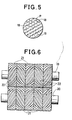
- a veneer sheet P to be tenderized is thus pressed and cracked, as, for example, shown in Fig. 5 wherein solid lines indicate the pressing of the sheet by the upper projection tops and dotted lines indicate the pressing thereof by the lower projection tops and numeral 18 designates the-cracks.
- the rolls 10 and 11, with the spiral projections 16 and 17, may be manufactured more easily at a lower cost than the preceding rolls 1 and 2.
- rotatable rolls as shown in Figs. 1 and 2 and in Fig. 4 are integral with their respective central shafts 3,4 and 12,13.
- a plurality of narrow annular rolls may be removably connected to a rotatable central shaft.
- a plurality of annular rolls 21 each, illustratively having a small width or thickness of approximately 40 mm and a diameter of approximately 295 mm, is each provided with a number of spiral, angular projections 22 at its circumference.
- the rolls 21 are removably mounted, side by side with aligned axis of rotation, around a central rotatable shaft 19 or 20 by keying means and keyways.
- the central rotatable shafts 19 and 20 have parallel axes of rotation.
- the spiral, angular projections 22 of each roll 21 have a vertical cross section similar to those of the preceding projections 16 and 17, and thus are edged at their tops, and, as with the projections 16 and 17, are located at regular intervals as well as at regular pitches.
- Either of the upper and lower rotatable rolls 21 collectively provides a means similar to any one of the preceding single rolls not only in its general shape, but in its function. However, the construction of the roll 21 of Fig.
- FIG. 6 is distinguished from that of the roll 16 or 17 of Fig. 4.
- the upper spiral projections 22 in Fig. 6 run in the same direction as the corresponding lower ones 22, but each pair of corresponding upper and lower spiral projections 22,22 runs in a different direction from the adjacent pair or pairs, so that the spiral projections 22, as a whole, run in zigzags or alternate.
- a veneer sheet is pressed as shown in Fig. 5 at its portions passing between the second and fourth rolls from the rightmost ones, but is pressed at its portions passing between the other rolls in such a manner that the solid lines of Fig. 5 change places with the dotted lines thereof.
- Such a configuration of spiral projections as in the apparatus of Fig. 6 enables the tenderizing of veneer sheets without a drawback of the construction of Fig. 4, in that veneer sheets of certain materials may tend to curve or curl in a direction perpendicular to the spiral projections 16 and 17 (Fig. 4) while they are being pressed.
- the apparatus of Fig. 6 avoids this advantage because the zigzag arrangement of the spiral projections in Fig. 6 may cancel the forces which otherwise tend to curve the veneer sheet in the different directions.
- Fig. 6 has an economic advantage for, if any one of the rolls 21 is damaged for example by foreign objects, the apparatus can be repaired by replacing only the damaged roll. Moreover, the relative locations of the rolls 21 may be changed to provide a construction suitable for the tenderizing of a particular veneer sheet, or any one of the rolls 21,may be replaced with another annular roll for the same purpose.
- FIG. 7 Another embodiment of the invention employs the same upper roll as the roll 1 of Fig. 2 and a plurality of removable annular lower rolls, as shown in Fig. 7 or 8.
- an upper rotatable roll 23 having the same construction as the roll 1 of Fig. 2 is used in combination with a plurality of annular lower rolls 25, which are removably mounted, side by side, around a central rotatable shaft 26.
- the upper roll 23 and the lower rolls 25 have parallel axes of rotation.
- Each roll 25 is provided with a number of angular projections 27 extending axially, on its circumference, from one end to the other end thereof.
- Each angular projection 27 of each lower roll 25 has a vertical cross section similar to that of each projection of the upper roll 23, and thus has an edged top.
- the projections 27 of each lower roll 25 are located at regular pitches, along the direction of rotation thereof, i.e., about the circumference, without being spaced apart from one another.
- the projections 27 hence are arranged circumferentially in the same manner as the projections 8 of the roll 2 of Fig. 2.
- the foregoing pitches are the same for all projections 27 of the lower rolls 25.
- each lower roll 25 is so mounted that the edged tops of its projections 27 are arranged at one half of the foregoing pitch relative to those of the projections of the adjacent lower roll or rolls 25.
- each projection of each roll 25 is in alignment not with that of the adjacent roll or rolls 25, but with that of next roll but one, i.e., the rolls 25,25 are in an alternating arrangement relative to the tops of the projections 27 on each.
- a veneer sheet to be tenderized is so orientated that its fibers run in directions substantially perpendicular to the direction of conveyance thereof between the rotatable rolls 23 and 25, and is conveyed between them so that the sheet is partly cracked in a manner similar to that in the case of the construction of Fig. 2.
- the construction of Fig. 7 is different from that of Fig. 2 in the following,respect.
- the cracks of the sheet brought about by the upper and lower projections 7 and 8 may be more or less continuously aligned with one another along the lower projections 8.
- Fig. 7 may be modified by replacing its removable and rotatable, annular lower rolls 25 with rolls 29 and 30 of Fig. 8.
- the removable annular lower rolls 29 and 30 are arranged alternately along and around a central rotatable shaft 26.
- the rolls 29 are provided with angular projections having the same shape and located in the same manner as those 27 of Fig. 7, while the other rolls 30 are provided with angular projections which have edged tops and axially extend like those of the rolls 29, but are circumferentially spaced apart from one another.
- the spacings or distance between the projections of each roll 30 are regular, and rather large so that the projections of each roll 30 are smaller in number than those of each roll 29.
- each projection of each roll 30 has a rather smaller width than that of the roll 29.
- the portions of the sheet pressed by the upper roll 23 and by the'lower rolls 29 are cracked as, for example, shown in Fig. 3, so that these portions elongate or stretch.
- the portions of the sheet pressed by the upper roll 23 and by the lower rolls 30 are deformed where the projections on these rolls intersect each other, and a tensile force is produced between the elongated portions and the deformed sections, so that the portions of the sheet pressed by the rolls 23 and 30 are also cracked.
- a number of cracks may be produced with a relatively small pressure.
- Veneer sheets of certain materials may elongate differently at different portions when cracked during the tenderizing operation, and it is possible that a portion of such a veneer sheet which has elongated only to a slight degree may "brake" the entire sheet exiting from the rolls and thus the entire sheet may turn aside and drop from the conveyance line. This may be prevented by omitting some of the projections from the upper and/or lower roll.
- An example of such a partial omission of the projections is illustrated in Fig. 6 where some of the projections are omitted from the circumferences of both upper roll and lower roll, as indicated by the letter C.
- the veneer sheet When using such a construction, the veneer sheet will have one portion with no cracks every time the rolls have made one rotation and, thus, if a portion of the sheet elongates differently from others when cracked, such a portion may automatically and elastically resume its normal shape, owing to the presence of the crack-free portions adjacent thereto. Therefore, a number of veneer sheets may be continuously processed without interruption which would occur if even one of them dropped from the conveyance line.
- the shafts of the upper roll (or roll means) and of the lower roll (or roll means) are supported by a frame structure (not shown) which mounts the two central shafts so that the crests of the projections of the upper roll (or roll means) and the crests of the projections of the lower roll (or roll means) have a clearance therebetween smaller than the thickness of the veneer sheet when the projections of the two rolls are opposite each other during the rotation of the rolls.
- Fig. 10 illustrates still another tenderizing apparatus according to the invention which comprises a pair of upper and lower pressing devices.
- the upper pressing device includes three deflecting rollers 41, 43 and 45.
- the lower pressing device also includes three deflecting rollers 42, 44 and 46.
- Steel belts 47 and 48 pass around the upper and lower combinations of deflecting rollers, respectively.
- the upper and lower rollers 41 and 42 may be rotated by a drive means (not shown).
- Projections 49 similar to the projections 7 of Fig. 2 are formed on the upper steel belt 47 along the direction of rotation of the roller 41, while projections 50 similar to the projections 8 of Fig. 2 are formed on the lower steel belt 48 along the axis of the roller 42.
- each projection 49 of the upper belt 47 is notched at regular intervals along the direction of rotation of the roller 41 so that it may flex around the rollers 41, 43 and 45.
- the upper and lower projections 49 and 50 press against a veneer sheet P to tenderize it when the sheet P is passed between the rollers 41 and 42.
- each roller has an appreciably different diameter from the other rollers, such an embodiment as shown in Fig. 10 may be constructed with, for example, the roller 41 or 42 and the roller 45 or 46 having the same diameter.
- ratios of the diameters of the rollers as illustrated in Fig. 10 may be selected to economise the manufacture of. the tenderizing apparatus.
- any one of the foregoing tenderizing apparatus veneer chips or decomposed veneer portions may be caught between the projections, during the tenderizing operation, so that the projections cannot effectively press the veneer sheets unless such foreign objects are removed.
- This problem may be solved, however, by a method illustrated with reference to Fig. 11.
- an elastic material 31 such as crude or urethane rubber is applied to a pair of rolls to fill the spaces between the projections, in advance, to a level lower than, but very close to, the level of the tops of the projections. If debris such as veneer chips presses against the elastic material 31 between the projections, the elastomer 31 is compressed to a certain degree, but finally resists the force of the chips and returns to its original shape, expelling them.
- An important aspect of the invention resides in pressing veneer sheets with upper and lower projections of rigid material which intersect each other with veneer sheets between.
- the projections intersect in the sense that the projections are located along paths or imaginary lines on an upper roller which cross and hence intersect the projection paths on a lower roller, when the rollers are viewed from above or from below.
- the projections have been described as tapering outward to provide edged tops, it is not necessarily required that the projections have "edges" in order to press and thereby tenderize the sheets
- the projections may be so formed as to have certain flat tops for pressing or tenderizing the sheets.
- the edged tops of the projections may still press the sheets effectively, as long as the flatness or extent thereof-does not exceed a certain limit.
- the invention can be practiced with numerous kinds of rigid material for the projections, and with different numbers thereof, and the like, as those skilled in the art may select in view of this disclosure.
- an upper or lower projection does not necessarily extend continuously. It is sufficient if the projections intersect each other, with veneer sheets between, at sufficient points to attain the desired level of tenderization.
- both the axial lengths of the rollers and the widths of the steel belts, as well as the diameters of the rollers may be selected in accordance with the dimensions and kind of wood of veneer sheets.
- the projections 7 (Fig. 2), 16 and 17 (Fig. 4) and 22 (Fig. 6) are spaced apart from one another.
- these projections may be continuous like the other projections. That is to say, it is sufficient if the projections are arranged at pitches which yield adequate tenderization of veneer sheets.
- the projections of any foregoing tenderizing apparatus may wear down first at intersections with other projections than elsewhere, and when the intersecting locations can no longer produce the desired cracks, the upper and lower rolls may be so relocated relative to each other that their projections intersect at different locations to perform again the desired functions.
- the foregoing problem may be solved by providing the pressing rolls, at the locations corresponding to the tapes on the sheet and at regular intervals (for example, of 5 mm), with cutters which form selected angles with the rolls and which cut into the tapes and the sheet surface to a required depth.
- the tapes on the sheet are cut obliquely, as the sheet is passed between the pressing rolls, so that the end portions of the sheet, on which the tapes are attached, are allowed to elongate like the other portions of the sheet, while at the same time the whole sheet is protected against reduction of its mechanical strength in the directions perpendicular to the fibers because the tapes are not cut parallel with the sheet fibers.
- spiral projections such as the projections 16 and 17 of Fig. 4 perform the same function as the foregoing cutters.
Landscapes
- Life Sciences & Earth Sciences (AREA)
- Engineering & Computer Science (AREA)
- Mechanical Engineering (AREA)
- Wood Science & Technology (AREA)
- Forests & Forestry (AREA)
- Veneer Processing And Manufacture Of Plywood (AREA)
Applications Claiming Priority (2)
| Application Number | Priority Date | Filing Date | Title |
|---|---|---|---|
| JP61082492A JPH0829522B2 (ja) | 1986-04-10 | 1986-04-10 | ベニヤ単板のテンダ−ライジング装置 |
| JP82492/86 | 1986-04-10 |
Publications (3)
| Publication Number | Publication Date |
|---|---|
| EP0241302A2 true EP0241302A2 (fr) | 1987-10-14 |
| EP0241302A3 EP0241302A3 (en) | 1990-01-31 |
| EP0241302B1 EP0241302B1 (fr) | 1993-02-24 |
Family
ID=13775991
Family Applications (1)
| Application Number | Title | Priority Date | Filing Date |
|---|---|---|---|
| EP87303144A Expired - Lifetime EP0241302B1 (fr) | 1986-04-10 | 1987-04-10 | Dispositif d'assouplissement pour des feuilles de placages |
Country Status (8)
| Country | Link |
|---|---|
| US (1) | US4796680A (fr) |
| EP (1) | EP0241302B1 (fr) |
| JP (1) | JPH0829522B2 (fr) |
| CN (1) | CN1009626B (fr) |
| BR (1) | BR8701655A (fr) |
| CA (1) | CA1286570C (fr) |
| DE (1) | DE3784262T2 (fr) |
| FI (1) | FI86389C (fr) |
Cited By (1)
| Publication number | Priority date | Publication date | Assignee | Title |
|---|---|---|---|---|
| CN101642917B (zh) * | 2009-08-21 | 2011-09-21 | 东莞台升家具有限公司 | 两夹片层结构的硬质木薄片的生产方法 |
Families Citing this family (11)
| Publication number | Priority date | Publication date | Assignee | Title |
|---|---|---|---|---|
| JP2584238B2 (ja) * | 1987-08-13 | 1997-02-26 | 株式会社 名南製作所 | ベニヤ単板のテンダ−ライジング装置 |
| US5129435A (en) * | 1990-11-15 | 1992-07-14 | Masonite Corporation | Apparatus and method for improving fiberboard mat moldability |
| US5179986A (en) * | 1990-11-15 | 1993-01-19 | Masonite Corporation | Method for improving fiberboard mat moldability |
| JPH07186106A (ja) * | 1993-12-27 | 1995-07-25 | Meinan Mach Works Inc | 針葉樹ベニヤ単板の脱水装置 |
| CN1081114C (zh) * | 1996-07-16 | 2002-03-20 | 唐吉凤 | 一种模压复合胶合板的制备工艺 |
| CN101224590B (zh) * | 2008-02-01 | 2012-11-21 | 中国林业科学研究院木材工业研究所 | 一种人造板单板单元及其制备方法 |
| US8046885B1 (en) * | 2008-06-02 | 2011-11-01 | Superba | Apparatus and methods for crimping textile threads |
| JP2010195572A (ja) * | 2009-02-27 | 2010-09-09 | Konica Minolta Business Technologies Inc | デカーラ装置及び画像形成装置 |
| US9629390B1 (en) * | 2013-01-26 | 2017-04-25 | Turner Innovations Ltd. | Sorrel harvesting machine with spaced apart rotating return and cutting drums moving in opposite directions at a throat therebetween |
| DE102014105672B4 (de) * | 2014-04-22 | 2020-10-29 | Hermann Schwelling | Vorrichtung zum Zusammendrücken von Behältern |
| US11052269B1 (en) * | 2020-05-01 | 2021-07-06 | II Michael D. Greenway | Protective face masks |
Citations (12)
| Publication number | Priority date | Publication date | Assignee | Title |
|---|---|---|---|---|
| FR363517A (fr) * | 1906-02-21 | 1906-08-02 | Louis Vallier | Machine à palissonner les peaux |
| US1384991A (en) * | 1921-03-09 | 1921-07-19 | Alfonzo F Combs | Meat-tendering machine |
| GB348416A (en) * | 1930-06-02 | 1931-05-14 | Elmendorf Armin | Improvements relating to reinforced wood veneer |
| US2974697A (en) * | 1958-01-10 | 1961-03-14 | Elmendorf Res Inc | Method and apparatus for making a veneer product |
| FR1537316A (fr) * | 1967-09-13 | 1968-08-23 | Sperry Rand Corp | Rouleau de conditionnement du fourrage |
| DE2055244A1 (de) * | 1969-11-06 | 1971-05-13 | The Goodyear Tire & Rubber Co, Akron, Ohio (V St A ) | Heu Konditionierungswalze |
| US3674219A (en) * | 1970-07-24 | 1972-07-04 | Tennessee Valley Authority | Green-wood fibrating means and method |
| JPS48102274U (fr) * | 1972-03-08 | 1973-11-30 | ||
| GB2098907A (en) * | 1981-05-14 | 1982-12-01 | Hashimoto Denki Co Ltd | Veneer peeling apparatus |
| US4558725A (en) * | 1984-04-02 | 1985-12-17 | Westvaco Corporation | Longitudinal tenderizing of veneer |
| GB2179592A (en) * | 1985-08-28 | 1987-03-11 | Meinan Machinery Works | Veneer processing apparatus |
| GB2179595A (en) * | 1985-08-30 | 1987-03-11 | Allan Weare | Device to hold coins or tablets |
Family Cites Families (6)
| Publication number | Priority date | Publication date | Assignee | Title |
|---|---|---|---|---|
| US609114A (en) * | 1898-08-16 | Machine for preparing wood for fuel | ||
| US3718959A (en) * | 1971-02-11 | 1973-03-06 | V Sailas | Roll for dewatering presses of paper making machines |
| US3969802A (en) * | 1974-04-25 | 1976-07-20 | Jean Bouvet | Mill roll |
| JPS5521474Y2 (fr) * | 1975-08-04 | 1980-05-23 | ||
| US4655869A (en) * | 1980-08-08 | 1987-04-07 | Tellman Stephen J | Method and apparatus for making expanded wood veneer products |
| JPS61107084A (ja) * | 1984-10-30 | 1986-05-24 | 株式会社名南製作所 | 生単板の含有水分除去装置 |
-
1986
- 1986-04-10 JP JP61082492A patent/JPH0829522B2/ja not_active Expired - Lifetime
-
1987
- 1987-04-07 FI FI871516A patent/FI86389C/fi not_active IP Right Cessation
- 1987-04-08 US US07/036,004 patent/US4796680A/en not_active Expired - Fee Related
- 1987-04-08 BR BR8701655A patent/BR8701655A/pt not_active IP Right Cessation
- 1987-04-09 CA CA000534252A patent/CA1286570C/fr not_active Expired - Fee Related
- 1987-04-10 CN CN87102760.7A patent/CN1009626B/zh not_active Expired
- 1987-04-10 EP EP87303144A patent/EP0241302B1/fr not_active Expired - Lifetime
- 1987-04-10 DE DE8787303144T patent/DE3784262T2/de not_active Expired - Fee Related
Patent Citations (12)
| Publication number | Priority date | Publication date | Assignee | Title |
|---|---|---|---|---|
| FR363517A (fr) * | 1906-02-21 | 1906-08-02 | Louis Vallier | Machine à palissonner les peaux |
| US1384991A (en) * | 1921-03-09 | 1921-07-19 | Alfonzo F Combs | Meat-tendering machine |
| GB348416A (en) * | 1930-06-02 | 1931-05-14 | Elmendorf Armin | Improvements relating to reinforced wood veneer |
| US2974697A (en) * | 1958-01-10 | 1961-03-14 | Elmendorf Res Inc | Method and apparatus for making a veneer product |
| FR1537316A (fr) * | 1967-09-13 | 1968-08-23 | Sperry Rand Corp | Rouleau de conditionnement du fourrage |
| DE2055244A1 (de) * | 1969-11-06 | 1971-05-13 | The Goodyear Tire & Rubber Co, Akron, Ohio (V St A ) | Heu Konditionierungswalze |
| US3674219A (en) * | 1970-07-24 | 1972-07-04 | Tennessee Valley Authority | Green-wood fibrating means and method |
| JPS48102274U (fr) * | 1972-03-08 | 1973-11-30 | ||
| GB2098907A (en) * | 1981-05-14 | 1982-12-01 | Hashimoto Denki Co Ltd | Veneer peeling apparatus |
| US4558725A (en) * | 1984-04-02 | 1985-12-17 | Westvaco Corporation | Longitudinal tenderizing of veneer |
| GB2179592A (en) * | 1985-08-28 | 1987-03-11 | Meinan Machinery Works | Veneer processing apparatus |
| GB2179595A (en) * | 1985-08-30 | 1987-03-11 | Allan Weare | Device to hold coins or tablets |
Cited By (1)
| Publication number | Priority date | Publication date | Assignee | Title |
|---|---|---|---|---|
| CN101642917B (zh) * | 2009-08-21 | 2011-09-21 | 东莞台升家具有限公司 | 两夹片层结构的硬质木薄片的生产方法 |
Also Published As
| Publication number | Publication date |
|---|---|
| CN1009626B (zh) | 1990-09-19 |
| EP0241302B1 (fr) | 1993-02-24 |
| US4796680A (en) | 1989-01-10 |
| DE3784262D1 (de) | 1993-04-01 |
| EP0241302A3 (en) | 1990-01-31 |
| DE3784262T2 (de) | 1993-06-09 |
| FI871516A0 (fi) | 1987-04-07 |
| CN87102760A (zh) | 1987-10-28 |
| BR8701655A (pt) | 1988-01-12 |
| FI86389B (fi) | 1992-05-15 |
| JPS6339302A (ja) | 1988-02-19 |
| FI86389C (fi) | 1992-08-25 |
| CA1286570C (fr) | 1991-07-23 |
| JPH0829522B2 (ja) | 1996-03-27 |
| FI871516A (fi) | 1987-10-11 |
Similar Documents
| Publication | Publication Date | Title |
|---|---|---|
| EP0241302B1 (fr) | Dispositif d'assouplissement pour des feuilles de placages | |
| US4944462A (en) | Shredder | |
| US4921643A (en) | Web processing with two mated rolls | |
| US4442876A (en) | Apparatus for drying veneer sheet | |
| US4718338A (en) | Veneer processing apparatus | |
| US4691629A (en) | Apparatus for dehydrating crude veneer | |
| US6155319A (en) | Unit for joining paper sheets together in corrugated board manufacturing equipment | |
| US5234040A (en) | Veneer dehydrating apparatus | |
| JPH07186106A (ja) | 針葉樹ベニヤ単板の脱水装置 | |
| GB2025314A (en) | Method of and Apparatus for Preventing Curling of Veneer | |
| EP1190822A2 (fr) | Appareil de déshydratation pour placage | |
| US4850404A (en) | Veneer tenderizing device | |
| CA2024212A1 (fr) | Machine pour le decoupage en bandes etroites d'une tole de grande largeur | |
| EP0403089B1 (fr) | Dispositif et méthode pour entailler des feuilles | |
| EP1144738B1 (fr) | Procede et dispositif pour couper des fibres en morceaux | |
| US4953712A (en) | Grading rolls for agricultural, horticultural and other articles | |
| EP0962293B1 (fr) | Machine de fendage | |
| FI116635B (fi) | Tela, sen käyttö, ylipaksun hakkeen käsittelylaite ja menetelmä puuhakkeen ohjaamiseksi | |
| KR810001004B1 (ko) | 베니어 판의 연화 방법 | |
| CN1190454A (zh) | 构件接合装置 | |
| KR850000439B1 (ko) | 베니어단판의 건조 방법 | |
| FI72910C (fi) | Foerfarande och anordning foer boejliggoerning av faner. | |
| JPH0425282Y2 (fr) | ||
| JPS6126004Y2 (fr) | ||
| EP0965551A3 (fr) | Appareil pour plier des produits imprimés ou des produits en papier |
Legal Events
| Date | Code | Title | Description |
|---|---|---|---|
| PUAI | Public reference made under article 153(3) epc to a published international application that has entered the european phase |
Free format text: ORIGINAL CODE: 0009012 |
|
| AK | Designated contracting states |
Kind code of ref document: A2 Designated state(s): DE GB IT |
|
| PUAL | Search report despatched |
Free format text: ORIGINAL CODE: 0009013 |
|
| AK | Designated contracting states |
Kind code of ref document: A3 Designated state(s): DE GB IT |
|
| 17P | Request for examination filed |
Effective date: 19900310 |
|
| 17Q | First examination report despatched |
Effective date: 19920403 |
|
| GRAA | (expected) grant |
Free format text: ORIGINAL CODE: 0009210 |
|
| ITF | It: translation for a ep patent filed |
Owner name: BARZANO' E ZANARDO MILANO S.P.A. |
|
| AK | Designated contracting states |
Kind code of ref document: B1 Designated state(s): DE GB IT |
|
| REF | Corresponds to: |
Ref document number: 3784262 Country of ref document: DE Date of ref document: 19930401 |
|
| PG25 | Lapsed in a contracting state [announced via postgrant information from national office to epo] |
Ref country code: GB Effective date: 19930524 |
|
| PGFP | Annual fee paid to national office [announced via postgrant information from national office to epo] |
Ref country code: DE Payment date: 19930626 Year of fee payment: 7 |
|
| PLBE | No opposition filed within time limit |
Free format text: ORIGINAL CODE: 0009261 |
|
| STAA | Information on the status of an ep patent application or granted ep patent |
Free format text: STATUS: NO OPPOSITION FILED WITHIN TIME LIMIT |
|
| GBPC | Gb: european patent ceased through non-payment of renewal fee |
Effective date: 19930524 |
|
| 26N | No opposition filed | ||
| PG25 | Lapsed in a contracting state [announced via postgrant information from national office to epo] |
Ref country code: DE Effective date: 19950103 |
|
| PG25 | Lapsed in a contracting state [announced via postgrant information from national office to epo] |
Ref country code: IT Free format text: LAPSE BECAUSE OF NON-PAYMENT OF DUE FEES;WARNING: LAPSES OF ITALIAN PATENTS WITH EFFECTIVE DATE BEFORE 2007 MAY HAVE OCCURRED AT ANY TIME BEFORE 2007. THE CORRECT EFFECTIVE DATE MAY BE DIFFERENT FROM THE ONE RECORDED. Effective date: 20050410 |