EP0240968B1 - Dispositif pour l'insertion méchanique des joints d'étanchéité - Google Patents
Dispositif pour l'insertion méchanique des joints d'étanchéité Download PDFInfo
- Publication number
- EP0240968B1 EP0240968B1 EP87105050A EP87105050A EP0240968B1 EP 0240968 B1 EP0240968 B1 EP 0240968B1 EP 87105050 A EP87105050 A EP 87105050A EP 87105050 A EP87105050 A EP 87105050A EP 0240968 B1 EP0240968 B1 EP 0240968B1
- Authority
- EP
- European Patent Office
- Prior art keywords
- seal
- frame
- sash
- tool
- seals
- Prior art date
- Legal status (The legal status is an assumption and is not a legal conclusion. Google has not performed a legal analysis and makes no representation as to the accuracy of the status listed.)
- Expired - Lifetime
Links
Images
Classifications
-
- B—PERFORMING OPERATIONS; TRANSPORTING
- B23—MACHINE TOOLS; METAL-WORKING NOT OTHERWISE PROVIDED FOR
- B23P—METAL-WORKING NOT OTHERWISE PROVIDED FOR; COMBINED OPERATIONS; UNIVERSAL MACHINE TOOLS
- B23P19/00—Machines for simply fitting together or separating metal parts or objects, or metal and non-metal parts, whether or not involving some deformation; Tools or devices therefor so far as not provided for in other classes
- B23P19/04—Machines for simply fitting together or separating metal parts or objects, or metal and non-metal parts, whether or not involving some deformation; Tools or devices therefor so far as not provided for in other classes for assembling or disassembling parts
- B23P19/047—Machines for simply fitting together or separating metal parts or objects, or metal and non-metal parts, whether or not involving some deformation; Tools or devices therefor so far as not provided for in other classes for assembling or disassembling parts for flexible profiles, e.g. sealing or decorating strips in grooves or on other profiles by devices moving along the flexible profile
Definitions
- the invention relates to a device for mechanically pressing seals in sashes and frames of windows, which are later provided with grooves that receive the seal, consisting of a frame or sash-receiving stand and a pressing tool for the seals and a cutting device that is mounted on a slide are attached.
- the invention has set itself the task of further developing such devices in such a way that a substantial acceleration of the work cycle and improvement of the product quality can be achieved.
- Such a configuration of the press-in device allows the sash or frame, which is brought onto the stand in the usual way with a conveyor belt, to be fixed there and the seal to be guided around a corner in a single continuous operation. If, for example, the insertion tool can be pivoted through 360 degrees, the coherent seal can be placed around all corners, so that a self-contained sealing course is created. It is then no longer necessary that the gasket must be mitred at the corner points, as required in the prior art, but that it can be inserted all around in the corners and in a single operation. It is fundamentally irrelevant in the context of the invention in what manner the specific design of the rotatability of the pressing tools, cutting devices and the like. he follows.
- the frame or sash is made of, in particular whether they are made of plastic, metal or wood.
- the movement of the insertion tool is controlled in the area of the corner point so that when it reaches it, it moves back by a sealing thickness, then swiveled by 90 degrees and pressed in again at the same point and then the seal is pulled in at the other coordinate. This movement of the insertion tool in the area of the corner point results in a precise insertion of the seal in this area.
- the slide which is displaceable in one plane, is equipped with a plurality of insertion tools, in order to be able to use d.
- insertion tools in order to be able to use d.
- H. windows with several parallel seals to be able to insert and insert them simultaneously and in a single operation.
- the seals are elongated by pulling them off a supply roll, so that the length greater than the corresponding geometric dimension of the groove to be accommodated must be selected in their dimensioning, since after the seal has been pressed in, the seal returns to its normal state and thereby shortened. This can be corrected and compensated for by appropriate consideration and adjustment when the seals are removed. Otherwise there would be gaps in the retracted seal. It also proves to be an advantage here that the gasket is not separated at the corner points but rotates so that length compensation is also easily possible "over a corner". Controlled addition to the length of the groove to be filled with the seal can compensate for the tension present due to the pulling off and the shortening subsequently caused thereby.
- the measurement of sash, frame or the like. is carried out in the usual way, for example optically using photocells or using ultrasound in a manner known per se.
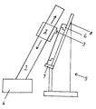
- a slide 2 is slidably mounted on a rail 1 which is inclined at a slight angle to the vertical, and a pressing-in tool 3 is attached to its outward-facing end face.
- the rail 1, which runs essentially in the vertical direction, is in turn movably fastened on a horizontal rail 4 arranged perpendicularly thereto and thus perpendicular to the plane of the drawing.
- the interaction of the two rails 1, 4, which run essentially perpendicular to one another, makes it possible to move the insertion tool 3 into any desired position in a plane spanned thereby.
- the frame 6 of a window is fastened on a stand 5, which in turn can be brought onto the stand 5 via a conveyor belt 7 and removed again.
- the frame 6 is supported on a rear wall 8, which then also runs parallel to the plane defined by the movement of the insertion tool 3.
- the measured values obtained serve as input signals for a control device for moving the insertion tool.
- the control could be set once via programming when working on a larger number of frames or sashes of the same size, so that an individual measurement of the dimension is neither necessary nor appears to be sensible.
- the proposed device allows a much faster, mechanical pressing of seals in sashes and frames of windows.
Claims (5)
- Dispositif pour le sertissage en machine de garnitures d'étanchéité dans des vantaux et cadres (6) de fenêtres, équipés de rainures destinées à recevoir ultérieurement la garniture d'étanchéité, consistant d'un support recevant le cadre ou le vantail et d'un outil de sertissage (3) pour les garnitures d'étanchéité ainsi que d'un dispositif de coupe monté sur un coulisseau, caractérisé en ce que le coulisseau (2) est mobile dans un plan essentiellement parallèle au plan défini par le cadre (6) ou le vantail, dans lequel l'outil de sertissage (3) est pivotant au moins de 90 degrés et que des moyens sont prévus qui, lorsque le point d'angle est atteint, reculent l'outil de sertissage (3) d'une épaisseur de garniture d'étanchéité, puis le font pivoter de 90 degrés et enfoncent à nouveau la garniture d'étanchéité au même point et pratiquent ensuite le sertissage de la garniture d'étanchéité suivant l'autre coordonnée.
- Dispositif selon revendication 1, caractérisé par plusieurs outils de sertissage (3.)
- Dispositif selon l'une des revendications 1 et 2, caractérisé en ce que le dispositif saisit les dimensions du cadre 6 ou du vantail avant le sertissage et que le dispositif de coupe sépare la longueur correspondante et contrôle le mouvement de l'outil de sertissage de façon appropriée.
- Dispositif selon la revendication 3, caractérisé en ce que la garniture d'étanchéité est plus longue que l'extension géométrique de la rainure correspondante.
- Dispositif selon la revendication 3 ou 4, caractérisé en ce que la mesure est effectuée de manière optique à l'aide de cellules photo-électriques ou au moyen d'ultra-sons.
Priority Applications (1)
| Application Number | Priority Date | Filing Date | Title |
|---|---|---|---|
| AT87105050T ATE82791T1 (de) | 1986-04-04 | 1987-04-04 | Vorrichtung zum maschinellen eindruecken von dichtungen. |
Applications Claiming Priority (2)
| Application Number | Priority Date | Filing Date | Title |
|---|---|---|---|
| DE19863611286 DE3611286A1 (de) | 1986-04-04 | 1986-04-04 | Vorrichtung zum automatischen einziehen von dichtungen |
| DE3611286 | 1986-04-04 |
Publications (3)
| Publication Number | Publication Date |
|---|---|
| EP0240968A2 EP0240968A2 (fr) | 1987-10-14 |
| EP0240968A3 EP0240968A3 (en) | 1988-08-17 |
| EP0240968B1 true EP0240968B1 (fr) | 1992-11-25 |
Family
ID=6297908
Family Applications (1)
| Application Number | Title | Priority Date | Filing Date |
|---|---|---|---|
| EP87105050A Expired - Lifetime EP0240968B1 (fr) | 1986-04-04 | 1987-04-04 | Dispositif pour l'insertion méchanique des joints d'étanchéité |
Country Status (3)
| Country | Link |
|---|---|
| EP (1) | EP0240968B1 (fr) |
| AT (1) | ATE82791T1 (fr) |
| DE (2) | DE3611286A1 (fr) |
Families Citing this family (10)
| Publication number | Priority date | Publication date | Assignee | Title |
|---|---|---|---|---|
| FR2645467B2 (fr) * | 1989-03-09 | 1994-07-13 | Ferco Internal | Mahine pour la pose automatique de joint souple, en particulier d'un joint exterieur dans une rainure de vantail |
| FR2644093B1 (fr) * | 1989-03-09 | 1994-05-20 | Ferco Internal Usine Ferrures Ba | Machine pour la pose automatique de joint souple, en particulier d'un joint exterieur dans une rainure de vantail |
| FR2655080B2 (fr) * | 1989-03-09 | 1994-07-13 | Ferco Internat Usine Ferrures | Machine pour la pose automatique de joints souples en particulier d'un joint exterieur dans une rainure de vantail. |
| FI900752A0 (fi) * | 1989-03-09 | 1990-02-14 | Ferco Int Usine Ferrures | Maskin foer automatisk montering av en elastisk taetning, i synnerhet en yttre taetning, i en foensterspringa. |
| FR2647150B1 (fr) * | 1989-05-17 | 1991-08-09 | Ferco Int Usine Ferrures | Machine de pose automatique de joint souple en particulier d'un joint de fond de vitrage ou d'un joint de parclose |
| FR2662107B1 (fr) * | 1990-05-21 | 1993-06-25 | Ferco Int Usine Ferrures | Machine automatique de pose de gaches sur des dormants de fenetres ou de porte-fenetres. |
| FR2673561B1 (fr) * | 1991-03-08 | 1995-02-24 | Ferco Int Usine Ferrures | Dispositif automatique de pose d'un joint souple, en particulier d'un joint exterieur dans une rainure de vantail. |
| DE4221164C2 (de) * | 1992-06-27 | 1994-11-17 | Lemuth Praezisionsteile Gmbh | Vorrichtung zum automatischen Eindrücken von Dichtungen |
| DE4411431C1 (de) * | 1994-03-31 | 1995-12-14 | Bayerische Motoren Werke Ag | Vorrichtung zum Anbringen eines eine Dichtungslippe und einen umgreifenden Abschnitt aufweisenden Dichtungskörpers |
| DE10360097B4 (de) * | 2003-12-20 | 2007-06-21 | Hüttenhölscher Maschinenbau GmbH | Verfahren und Vorrichtung zum Einlegen eines Profilbandes in einen Aufnahmerahmen für eine Platte |
Family Cites Families (5)
| Publication number | Priority date | Publication date | Assignee | Title |
|---|---|---|---|---|
| DE2915282A1 (de) * | 1979-04-14 | 1980-10-23 | Ludolf Stegherr | Einrichtung zum einsetzen von dichtungselementen in die nuten von falzen bei werkstuecken, wie fenster-, tuer- und wandelementen |
| FR2520793A1 (fr) * | 1982-01-29 | 1983-08-05 | Thinet Menuiserie Marcel | Machine automatique destinee a la mise en place des joints d'etancheite dans les rainures notamment de profiles-bois |
| DE3243214A1 (de) * | 1982-11-23 | 1984-08-02 | Knaust, Klaus, 8740 Bad Neustadt | Einrichtung zum automatischen einziehen eines dichtungsstreifens in eine nut eines rahmens |
| FR2572123B1 (fr) * | 1984-10-22 | 1988-07-22 | Jaillet Jean | Machine a positionner les joints d'etancheite |
| US4620354A (en) * | 1985-05-28 | 1986-11-04 | General Motors Corporation | Method of applying weatherstrip to a vehicle body opening |
-
1986
- 1986-04-04 DE DE19863611286 patent/DE3611286A1/de not_active Withdrawn
-
1987
- 1987-04-04 DE DE8787105050T patent/DE3782758D1/de not_active Expired - Fee Related
- 1987-04-04 AT AT87105050T patent/ATE82791T1/de active
- 1987-04-04 EP EP87105050A patent/EP0240968B1/fr not_active Expired - Lifetime
Also Published As
| Publication number | Publication date |
|---|---|
| ATE82791T1 (de) | 1992-12-15 |
| EP0240968A3 (en) | 1988-08-17 |
| DE3782758D1 (de) | 1993-01-07 |
| DE3611286A1 (de) | 1987-10-08 |
| EP0240968A2 (fr) | 1987-10-14 |
Similar Documents
| Publication | Publication Date | Title |
|---|---|---|
| AT403350B (de) | Biegemaschine zum herstellen eines abstandhaltenden innenrahmens für eine isolierglasscheibe | |
| EP0164063B1 (fr) | Machine-outil pour l'usinage des planches | |
| EP0240968B1 (fr) | Dispositif pour l'insertion méchanique des joints d'étanchéité | |
| EP0009703B1 (fr) | Machine à cintrer pour la fabrication d'une entretoise pour des vitrages isolants | |
| EP0461100B2 (fr) | Procédé et dispositif pour plier des profilés d'écartement creux pour double vitrage | |
| DE2757886C2 (de) | Eckverbindungen und Vorrichtung zu deren Herstellung | |
| DE4401271C2 (de) | Abbundanlage mit Transporteinrichtungen | |
| EP0449801A2 (fr) | Dispositif pour plier des profilés d'écartement creux pour double vitrage | |
| DE2809152C3 (de) | Bohr-Fräsvorrichtung zum Einarbeiten von Schlitzen | |
| DE3508756A1 (de) | Vorrichtung zum bohren von loechern an den innenflaechen von abstandhalterrahmen fuer isolierglasscheiben | |
| DE2726382B2 (de) | Vorrichtung zum Bohren und Ausschneiden oder Fräsen eines Bauteiles aus einem plattenförmigen Werkstück aus Holz o.dgl | |
| DE19521368B4 (de) | Vorrichtung zum Erfassen von Meßgrößen | |
| DE3917146A1 (de) | Anschlagvorrichtung | |
| DE3817005A1 (de) | Schweissmaschine zur herstellung von rahmen | |
| DE2015414A1 (en) | Joining hollow sections to form window frames etc | |
| EP0455962B1 (fr) | Dispositif pour travailler les zones de jonction en bois naturel, en particulier de cadres pour châssis et dormants de fenêtre | |
| DE4409813A1 (de) | Vorrichtung zum Zuschneiden von stabförmigen Werkstücken, insbesondere von Glassprossen für Fenster oder Türen | |
| DE3008326A1 (de) | Vorrichtung zum verbinden von auf gehrung geschnittemenen metallprofilstaeben | |
| DE8333479U1 (de) | Vorrichtung zum Bearbeiten von Schweißraupen oder dgl. an Rahmenecken | |
| DE10302899A1 (de) | Vorrichtung zur Bearbeitung von stangenförmigen Profilen | |
| DE2030541C3 (de) | Maschinell rückbarer hydraulischer Ausbau | |
| DE8314930U1 (de) | Vorrichtung zum Verschwenken eines Rahmens oder dgl. um einen Winkel von 90° | |
| DE2910097C2 (de) | Vorrichtung zum Fräsen von Entwässerungsschlitzen in ein Fensterprofil | |
| AT312249B (de) | Maschine zum automatischen Herstellen von Rahmen oder rahmenähnlichen Gebilden | |
| DE19602537C2 (de) | Vorschubeinrichtung zum Transport von sich in Längsrichtung erstreckenden Werkstücken, zum Beispiel einem Balken oder einem Träger |
Legal Events
| Date | Code | Title | Description |
|---|---|---|---|
| PUAI | Public reference made under article 153(3) epc to a published international application that has entered the european phase |
Free format text: ORIGINAL CODE: 0009012 |
|
| AK | Designated contracting states |
Kind code of ref document: A2 Designated state(s): AT DE ES FR GB IT SE |
|
| PUAL | Search report despatched |
Free format text: ORIGINAL CODE: 0009013 |
|
| AK | Designated contracting states |
Kind code of ref document: A3 Designated state(s): AT DE ES FR GB IT SE |
|
| 17P | Request for examination filed |
Effective date: 19890127 |
|
| 17Q | First examination report despatched |
Effective date: 19890925 |
|
| 17Q | First examination report despatched |
Effective date: 19900718 |
|
| GRAA | (expected) grant |
Free format text: ORIGINAL CODE: 0009210 |
|
| AK | Designated contracting states |
Kind code of ref document: B1 Designated state(s): AT DE ES FR GB IT SE |
|
| PG25 | Lapsed in a contracting state [announced via postgrant information from national office to epo] |
Ref country code: SE Effective date: 19921125 |
|
| REF | Corresponds to: |
Ref document number: 82791 Country of ref document: AT Date of ref document: 19921215 Kind code of ref document: T |
|
| REF | Corresponds to: |
Ref document number: 3782758 Country of ref document: DE Date of ref document: 19930107 |
|
| ITF | It: translation for a ep patent filed |
Owner name: STEFANO KARAGHI0SOFF |
|
| GBT | Gb: translation of ep patent filed (gb section 77(6)(a)/1977) |
Effective date: 19930113 |
|
| ET | Fr: translation filed | ||
| PG25 | Lapsed in a contracting state [announced via postgrant information from national office to epo] |
Ref country code: ES Free format text: LAPSE BECAUSE OF FAILURE TO SUBMIT A TRANSLATION OF THE DESCRIPTION OR TO PAY THE FEE WITHIN THE PRESCRIBED TIME-LIMIT Effective date: 19930307 |
|
| PLBE | No opposition filed within time limit |
Free format text: ORIGINAL CODE: 0009261 |
|
| STAA | Information on the status of an ep patent application or granted ep patent |
Free format text: STATUS: NO OPPOSITION FILED WITHIN TIME LIMIT |
|
| 26N | No opposition filed | ||
| PGFP | Annual fee paid to national office [announced via postgrant information from national office to epo] |
Ref country code: GB Payment date: 19950316 Year of fee payment: 9 |
|
| PGFP | Annual fee paid to national office [announced via postgrant information from national office to epo] |
Ref country code: FR Payment date: 19950317 Year of fee payment: 9 |
|
| PGFP | Annual fee paid to national office [announced via postgrant information from national office to epo] |
Ref country code: AT Payment date: 19950420 Year of fee payment: 9 |
|
| PG25 | Lapsed in a contracting state [announced via postgrant information from national office to epo] |
Ref country code: GB Effective date: 19960404 Ref country code: AT Effective date: 19960404 |
|
| PGFP | Annual fee paid to national office [announced via postgrant information from national office to epo] |
Ref country code: DE Payment date: 19960607 Year of fee payment: 10 |
|
| GBPC | Gb: european patent ceased through non-payment of renewal fee |
Effective date: 19960404 |
|
| PG25 | Lapsed in a contracting state [announced via postgrant information from national office to epo] |
Ref country code: FR Effective date: 19961227 |
|
| REG | Reference to a national code |
Ref country code: FR Ref legal event code: ST |
|
| PG25 | Lapsed in a contracting state [announced via postgrant information from national office to epo] |
Ref country code: DE Free format text: LAPSE BECAUSE OF NON-PAYMENT OF DUE FEES Effective date: 19980101 |
|
| PG25 | Lapsed in a contracting state [announced via postgrant information from national office to epo] |
Ref country code: IT Free format text: LAPSE BECAUSE OF NON-PAYMENT OF DUE FEES;WARNING: LAPSES OF ITALIAN PATENTS WITH EFFECTIVE DATE BEFORE 2007 MAY HAVE OCCURRED AT ANY TIME BEFORE 2007. THE CORRECT EFFECTIVE DATE MAY BE DIFFERENT FROM THE ONE RECORDED. Effective date: 20050404 |