EP0240968B1 - Device for mechanically inserting sealing strips - Google Patents
Device for mechanically inserting sealing strips Download PDFInfo
- Publication number
- EP0240968B1 EP0240968B1 EP87105050A EP87105050A EP0240968B1 EP 0240968 B1 EP0240968 B1 EP 0240968B1 EP 87105050 A EP87105050 A EP 87105050A EP 87105050 A EP87105050 A EP 87105050A EP 0240968 B1 EP0240968 B1 EP 0240968B1
- Authority
- EP
- European Patent Office
- Prior art keywords
- seal
- frame
- sash
- tool
- seals
- Prior art date
- Legal status (The legal status is an assumption and is not a legal conclusion. Google has not performed a legal analysis and makes no representation as to the accuracy of the status listed.)
- Expired - Lifetime
Links
Images
Classifications
-
- B—PERFORMING OPERATIONS; TRANSPORTING
- B23—MACHINE TOOLS; METAL-WORKING NOT OTHERWISE PROVIDED FOR
- B23P—METAL-WORKING NOT OTHERWISE PROVIDED FOR; COMBINED OPERATIONS; UNIVERSAL MACHINE TOOLS
- B23P19/00—Machines for simply fitting together or separating metal parts or objects, or metal and non-metal parts, whether or not involving some deformation; Tools or devices therefor so far as not provided for in other classes
- B23P19/04—Machines for simply fitting together or separating metal parts or objects, or metal and non-metal parts, whether or not involving some deformation; Tools or devices therefor so far as not provided for in other classes for assembling or disassembling parts
- B23P19/047—Machines for simply fitting together or separating metal parts or objects, or metal and non-metal parts, whether or not involving some deformation; Tools or devices therefor so far as not provided for in other classes for assembling or disassembling parts for flexible profiles, e.g. sealing or decorating strips in grooves or on other profiles by devices moving along the flexible profile
Definitions
- the invention relates to a device for mechanically pressing seals in sashes and frames of windows, which are later provided with grooves that receive the seal, consisting of a frame or sash-receiving stand and a pressing tool for the seals and a cutting device that is mounted on a slide are attached.
- the invention has set itself the task of further developing such devices in such a way that a substantial acceleration of the work cycle and improvement of the product quality can be achieved.
- Such a configuration of the press-in device allows the sash or frame, which is brought onto the stand in the usual way with a conveyor belt, to be fixed there and the seal to be guided around a corner in a single continuous operation. If, for example, the insertion tool can be pivoted through 360 degrees, the coherent seal can be placed around all corners, so that a self-contained sealing course is created. It is then no longer necessary that the gasket must be mitred at the corner points, as required in the prior art, but that it can be inserted all around in the corners and in a single operation. It is fundamentally irrelevant in the context of the invention in what manner the specific design of the rotatability of the pressing tools, cutting devices and the like. he follows.
- the frame or sash is made of, in particular whether they are made of plastic, metal or wood.
- the movement of the insertion tool is controlled in the area of the corner point so that when it reaches it, it moves back by a sealing thickness, then swiveled by 90 degrees and pressed in again at the same point and then the seal is pulled in at the other coordinate. This movement of the insertion tool in the area of the corner point results in a precise insertion of the seal in this area.
- the slide which is displaceable in one plane, is equipped with a plurality of insertion tools, in order to be able to use d.
- insertion tools in order to be able to use d.
- H. windows with several parallel seals to be able to insert and insert them simultaneously and in a single operation.
- the seals are elongated by pulling them off a supply roll, so that the length greater than the corresponding geometric dimension of the groove to be accommodated must be selected in their dimensioning, since after the seal has been pressed in, the seal returns to its normal state and thereby shortened. This can be corrected and compensated for by appropriate consideration and adjustment when the seals are removed. Otherwise there would be gaps in the retracted seal. It also proves to be an advantage here that the gasket is not separated at the corner points but rotates so that length compensation is also easily possible "over a corner". Controlled addition to the length of the groove to be filled with the seal can compensate for the tension present due to the pulling off and the shortening subsequently caused thereby.
- the measurement of sash, frame or the like. is carried out in the usual way, for example optically using photocells or using ultrasound in a manner known per se.
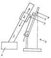
- a slide 2 is slidably mounted on a rail 1 which is inclined at a slight angle to the vertical, and a pressing-in tool 3 is attached to its outward-facing end face.
- the rail 1, which runs essentially in the vertical direction, is in turn movably fastened on a horizontal rail 4 arranged perpendicularly thereto and thus perpendicular to the plane of the drawing.
- the interaction of the two rails 1, 4, which run essentially perpendicular to one another, makes it possible to move the insertion tool 3 into any desired position in a plane spanned thereby.
- the frame 6 of a window is fastened on a stand 5, which in turn can be brought onto the stand 5 via a conveyor belt 7 and removed again.
- the frame 6 is supported on a rear wall 8, which then also runs parallel to the plane defined by the movement of the insertion tool 3.
- the measured values obtained serve as input signals for a control device for moving the insertion tool.
- the control could be set once via programming when working on a larger number of frames or sashes of the same size, so that an individual measurement of the dimension is neither necessary nor appears to be sensible.
- the proposed device allows a much faster, mechanical pressing of seals in sashes and frames of windows.
Abstract
Description
Die Erfindung betrifft eine Vorrichtung zum maschinellen Eindrücken von Dichtungen in Flügel und Rahmen von Fenstern, die mit später die Dichtung aufnehmenden Nuten versehen sind, bestehend aus einem den Rahmen oder Flügel aufnehmenden Ständer und einem Eindrückwerkzeug für die Dichtungen sowie einer Schneidevorrichtung, die auf einem Schlitten befestigt sind.The invention relates to a device for mechanically pressing seals in sashes and frames of windows, which are later provided with grooves that receive the seal, consisting of a frame or sash-receiving stand and a pressing tool for the seals and a cutting device that is mounted on a slide are attached.
Noch vor einigen Jahren wurden die Dichtungen insbesondere bei Rahmen und Flügeln von Fenstern zunächst zurecht geschnitten und dann per Hand in die entsprechenden Nuten eingedrückt. In jüngster Zeit werden hierfür Maschinen eingesetzt, die mit einem in einer Richtung bewegbaren Eindrückwerkzeug ausgerüstet sind und die den Dichtungsstreifen, abziehend von einer Vorratsrolle, in die Nut einführen und dort festlegen und mit Erreichen des Eckpunktes die Dichtung abschneiden. Daraufhin wird der Rahmen oder Flügel als Ganzes um 90 Grad geschwenkt und die Dichtung in eine senkrecht zur bisherigen Ebene verlaufende Nut eingebracht. Entscheidend ist, daß das Eindrückwerkzeug stets entlang einer raumfesten Geraden eine Bewegung ausführt und daß für das allseitige Einziehen in Rahmen oder Flügel diese im Ständer in der durch sie aufgespannten Ebene mit Erreichen eines Eckpunktes gedreht werden. Vorrichtungen dieser Art sind aus der EP - A - 0 110156 bekannt. Dies ist in mehrfacher Hinsicht als wesentlicher Nachteil anzusehen, da zum einen das Drehen durch das hohe Gewicht der Teile entsprechende apparative Maßnahmen erfordert und zum anderen hierdurch eine entscheidende Verlängerung der benötigten Arbeitszeit eintritt.A few years ago, the seals, especially for frames and sashes of windows, were first cut to size and then pressed into the corresponding grooves by hand. Recently, machines have been used for this purpose, which are equipped with a push-in tool that can be moved in one direction and that insert the sealing strip, pulling off a supply roll, into the groove and fix it there and cut off the seal when the corner point is reached. The frame or sash is then pivoted as a whole by 90 degrees and the seal is introduced into a groove running perpendicular to the previous plane. It is crucial that the insertion tool always executes a movement along a fixed straight line and that for the all-round retraction into frames or sashes these are rotated in the stand in the plane spanned by them when reaching a corner point. Devices of this type are known from EP-A-0 110156. This is to be regarded as a major disadvantage in several respects, since on the one hand the turning due to the high weight of the parts requires corresponding equipment measures and on the other hand this results in a decisive extension of the required working time.
Aus der DE-A- 2845475 ist die Verwendung einer in einer Ebene bewegbaren Fülldüse bekannt, die dem Einbringen der Füllmasse in die Randfuge einer Isolierglasscheibe dient. Dabei ist die Fülldüse nach Art eines zweidimensionalen kartesischen Koordinantensystems in der X- und Y-Richtung verschiebbar.From DE-A-2845475 it is known to use a filling nozzle which can be moved in one plane and which serves to introduce the filling compound into the edge joint of an insulating glass pane. The filling nozzle can be moved in the X and Y directions in the manner of a two-dimensional Cartesian coordinate system.
Hiervon ausgehend hat sich die Erfindung die Weiterentwicklung derartiger Vorrichtungen dahingehend zur Aufgabe gemacht, daß eine wesentliche Beschleunigung des Arbeitstaktes und Verbesserung der Produktqualität erreichbar wird.Proceeding from this, the invention has set itself the task of further developing such devices in such a way that a substantial acceleration of the work cycle and improvement of the product quality can be achieved.
Gelöst wird diese Aufgabe erfindungsgemäß durch die Merkmale im Kennzeichen des Anspruchs 1.According to the invention, this object is achieved by the features in the characterizing part of claim 1.
Eine derartige Ausgestaltung der Eindrückvorrichtung erlaubt den Flügel oder Rahmen, der in üblicher Weise mit einem Transportband auf den Ständer gebracht wird, dort festzulegen und die Dichtung in einem einzigen kontinuierlichen Arbeitsvorgang um eine Ecke herumzuführen. Ist das Eindrückwerkzeug beispielsweise um 360 Grad verschwenkbar, läßt sich die zusammenhängende Dichtung um sämtliche Ecken herumlegen, so daß ein in sich geschlossener Dichtungsverlauf entsteht. Es ist dann nicht mehr notwendig, daß in den Eckpunkten, wie im Stande der Technik erforderlich, die Dichtung auf Gehrung geschnitten werden muß, sondern daß sie in den Ecken umlaufend und in einem einzigen Arbeitsvorgang eingelegt werden kann. Hierbei ist im Rahmen der Erfindung grundsätzlich unerheblich, auf welche Art und Weise die konkrete Ausbildung der Drehbarkeit der Eindrückwerkzeuge, Schneidevorrichtungen udgl. erfolgt. Daneben spielt es auch keine Rolle, aus welchem Material Rahmen oder Flügel bestehen, insbesondere ob sie aus Kunststoff, aus Metall oder aus Holz aufgebaut sind. Die Bewegung des Eindrückwerkzeuges ist im Bereich des Eckpunktes so gesteuert, daß es mit Erreichen desselben um eine Dichtungsstärke zurückfährt, dann um 90 Grad verschwenkt und an demselben Punkt wieder eindrückt und anschließend das Einziehen der Dichtung in der anderen Koordinate vorgenommen wird. Diese Bewegung des eindrückwerkzeuges im Bereich des Eckpunktes ergibt ein präzises Eindrücken der Dichtung in diesem Bereich.Such a configuration of the press-in device allows the sash or frame, which is brought onto the stand in the usual way with a conveyor belt, to be fixed there and the seal to be guided around a corner in a single continuous operation. If, for example, the insertion tool can be pivoted through 360 degrees, the coherent seal can be placed around all corners, so that a self-contained sealing course is created. It is then no longer necessary that the gasket must be mitred at the corner points, as required in the prior art, but that it can be inserted all around in the corners and in a single operation. It is fundamentally irrelevant in the context of the invention in what manner the specific design of the rotatability of the pressing tools, cutting devices and the like. he follows. In addition, it does not matter what material the frame or sash is made of, in particular whether they are made of plastic, metal or wood. The movement of the insertion tool is controlled in the area of the corner point so that when it reaches it, it moves back by a sealing thickness, then swiveled by 90 degrees and pressed in again at the same point and then the seal is pulled in at the other coordinate. This movement of the insertion tool in the area of the corner point results in a precise insertion of the seal in this area.
Die mit Einsatz der erfindungsgemäßen Vorrichtung erreichbaren Vorteile sind vielfältig:
Da, wie bereits erwähnt, Rahmen oder Flügel raumfest bleiben und während des Eindrückvorganges der Dichtungen einzig und allein das Eindrückwerkzeug bewegt wird, erübrigt sich ein Drehen des Rahmens selbst, was einerseits eine erhebliche bauliche Vereinfachung und damit Verbilligung der Herstellung mit sich bringt und eine wesentliche Beschleunigung des Arbeitsvorganges bedeutet. Da gemäß der vorstehenden Schilderungen die Dichtung in den Ekken durchgehend verläuft, erübrigt sich das Schneiden in den Ecken auf Gehrung, wodurch zusätzliche Arbeitszeit eingespart wird. Dies ist auch unter dem Gesichtspunkt als Vorteil anzusehen, da die elastischen Dichtungen beim Schneiden grundsätzlich gequetscht werden, so daß keine gerade Schnittfläche entsteht und/oder komplizierte Schnittechniken angewendet werden müßten, um den Gehrungsschnitt zu erzeugen.
Bei einer umlaufenden Dichtung entfallen diese Probleme. Ebenso wie die bereits seit kurzem auf dem Markt befindlichen Vorrichtung ermöglicht die Erfindung ein maschinelles Arbeiten, so daß sich Handarbeit erübrigt, worin ebenfalls ein erheblicher Vorzug zu sehen ist.The advantages achievable with the use of the device according to the invention are numerous:
Since, as already mentioned, the frame or sash remain spatially fixed and only the pressing tool is moved during the pressing-in process of the seals, there is no need to turn the frame itself, which on the one hand brings about a considerable structural simplification and thus makes production cheaper and a substantial one Acceleration of the work process means. Since the seal in the corners runs continuously according to the above descriptions, there is no need to miter the corners, which saves additional working time. This is also to be regarded as an advantage from the point of view that the elastic seals are basically squeezed when cutting, so that no straight cut surface is created and / or complicated cutting techniques would have to be used to produce the miter cut.
These problems are eliminated with a circumferential seal. Like the device that has recently been on the market, the invention enables machine work, so that manual work is unnecessary, which also a significant asset can be seen.
In einer weiteren Ausgestaltung ist vorgesehen den in einer Ebene verschieblichen Schlitten mit mehreren Eindrückwerkzeugen auszustatten, um bei höherwertigen d. h. mit mehreren parallel verlaufenden Dichtungen versehenen Fenstern diese gleichzeitig und in einem einzigen Arbeitsvorgang einbringen und einlegen zu können.In a further embodiment, it is provided that the slide, which is displaceable in one plane, is equipped with a plurality of insertion tools, in order to be able to use d. H. windows with several parallel seals to be able to insert and insert them simultaneously and in a single operation.
Im Stande der Technik ist es bislang üblich, die Bewegung des Eindrückwerkzeuges dadurch zu steuern, daß es mit Erreichen des Eckpunktes und Betätigen über Endschalter oder Lichtschranken den Eindrückvorgang beendet und die Dichtung abschneidet. Das Meßen der jeweiligen Koordinate von Flügel oder Rahmen erfolgt dann gleichzeitig mit dem Eindrücken der Dichtung. Demgegenüber werden in einer bevorzugten Ausgestaltung sämtliche Abmessungen von Fenster oder Flügel vorher auf eine der üblichen Weisen festgestellt, die gesamte Länge der Dichtung bestimmt und dann erst mit dem Eindrückvorgang begonnen. Gleichzeitig wird entsprechend den erhaltenen Abmessungen die Bewegung des Eindrückwerkzeuges gesteuert, so daß nicht nur wie im Stande der Technik Rahmen und Flügel sondern ohne weiteres auch Kämpfer in beliebiger Höhe mit einer Dichtung versehen werden können.In the prior art it has been customary to control the movement of the insertion tool in that when the corner point is reached and actuated via limit switches or light barriers, it ends the insertion process and cuts off the seal. The respective coordinate of the sash or frame is then measured simultaneously with the pressing of the seal. In contrast, in a preferred embodiment, all dimensions of the window or sash are determined beforehand in one of the usual ways, the entire length of the seal is determined, and only then is the compression process started. At the same time, the movement of the insertion tool is controlled in accordance with the dimensions obtained, so that the frame and sash are not only as in the prior art but also fighters can be provided with a seal at any height.
In der Praxis stellt man fest, daß durch das Abziehen von einer Vorratsrolle die Dichtungen gelängt sind, so daß bei deren Bemessung die Länge größer als die entsprechende geometrische Ausdehnung der aufzunehmenden Nut gewählt werden muß, da nach dem Eindrücken die Dichtung in ihren Normalzustand zurückkehrt und dadurch verkürzt. Dies läßt sich durch entsprechende Berücksichtigung und Einstellung beim Abtrennen der Dichtungen korrigieren und ausgleichen. Andernfalls würden sich in der eingezogenen Dichtung Lücken ergeben. Auch erweist es sich hier als Vorteil, daß die Dichtung in den Eckpunkten nicht getrennt ist sondern umläuft, so daß ein Längenausgleich auch "über Eck" ohne weiteres möglich ist. Durch eine kontrollierte Zugabe zur Länge der mit der Dichtung auszufüllenden Nut läßt sich die durch das Abziehen vorhandene Spannung und die hierdurch später bedingte Verkürzung ausgleichen.In practice, it is found that the seals are elongated by pulling them off a supply roll, so that the length greater than the corresponding geometric dimension of the groove to be accommodated must be selected in their dimensioning, since after the seal has been pressed in, the seal returns to its normal state and thereby shortened. This can be corrected and compensated for by appropriate consideration and adjustment when the seals are removed. Otherwise there would be gaps in the retracted seal. It also proves to be an advantage here that the gasket is not separated at the corner points but rotates so that length compensation is also easily possible "over a corner". Controlled addition to the length of the groove to be filled with the seal can compensate for the tension present due to the pulling off and the shortening subsequently caused thereby.
Das Abmessen von Flügel, Rahmen odgl. erfolgt in der üblichen Weise, beispielsweise auf optischen Wegen mit Hilfe von Fotozellen oder mit Ultraschall in an sich bekannter Weise.The measurement of sash, frame or the like. is carried out in the usual way, for example optically using photocells or using ultrasound in a manner known per se.
Weitere Einzelheiten, Merkmale und Vorteile der Erfindung lassen sich dem nachfolgenden Beschreibungsteil entnehmen, in dem an Hand der Zeichnung ein Ausführungsbeispiel der Erfindung näher erläutert wird. Es zeigt in schematischer Darstellung eine Seitenansicht der erfindungsgemäßen Vorrichtung zum maschinellen Eindrücken von Dichtungen in Flügel und Rahmen von Fenstern.Further details, features and advantages of the invention can be found in the following description, in which an embodiment of the invention is explained in more detail with reference to the drawing becomes. It shows a schematic representation of a side view of the device according to the invention for mechanically pressing seals into the sash and frame of windows.
Auf einer in einem geringen Winkel gegen die Vertikale geneigten Schiene 1 ist ein Schlitten 2 verschieblich angebracht, an dessen nach außen weisender Stirnseite ein Eindrückwerkzeug 3 befestigt ist. Die im wesentlichen in vertikaler Richtung verlaufende Schiene 1 ist ihrerseits verfahrbar auf einer senkrechten hierzu und damit senkrecht zur Zeichenebene angeordneten horizontalen Schiene 4 befestigt. Durch Zusammenwirken der beiden im wesentlichen senkrecht zueinander verlaufenden Schienen 1, 4 wird es möglich, das Eindrückwerkzeug 3 in einer hierdurch aufgespannten Ebene in jede beliebige Position zu verfahren.A
Parallel zu dieser durch die möglichen Bewegungen des Schlittens definierten Ebene ist auf einem Ständer 5 der Rahmen 6 eines Fensters befestigt, der seinerseits über ein Transportband 7 auf den Ständer 5 gebracht und wieder heruntergenommen werden kann. Der Rahmen 6 ist hierbei abgestützt an eine Rückwand 8, die dann ebenfalls parallel zu der durch die Bewegung des Eindrückwerkzeugs 3 definierten Ebene verläuft.Parallel to this plane defined by the possible movements of the slide, the
Neben der Möglichkeit der Bewegung des Schlittens 2 mit dem daran befestigten Eindrückwerkzeug in einer Ebene ist für die Erfindung darüber hinaus entscheidend, daß das Eindrückwerkzeug 3 selbst verschwenkbar ist und deshalb in einer einzigen durchgehenden Bewegung umlaufend die Dichtung in den Rahmen 6 eingedrückt werden kann, der im Gegensatz zum Stande der Technik hierbei raumfest bleibt. Wie einerseits die Verschiebung des Schlittens 2 auf den Schienen 1, 4 und andererseits die Schwenkbewegung des Eindrückwerkzeuges 3 konkret realisiert werden, steht im Rahmen der Erfindung grundsätzlich frei, weshalb in der Zeichnung hierauf nicht eingegangen wurde. Denkbare Realisierungen bestehen in der Verwendung von Elektromotoren, hydraulischen Antrieben u. a. Weiterhin sind die grundsätzlich erforderliche Vorratsrolle für die Dichtungen, sowie Vorrichtungen zum Abrollen und Schneiden aus Gründen der Übersichtlichkeit nicht wiedergegeben und betreffen darüber hinaus den Kern der Erfindung nicht, können aber ohne weiteres und ohne nähere Angaben durch einen Fachmann konstruiert und gebaut werden.In addition to the possibility of moving the
Ebenfalls nicht eingezeichnet sind weitere mögliche Vorrichtungselemente zur Abmessung von Rahmen oder Flügel auf optischem Wege oder mit Hilfe von Ultraschall. Die dabei erhaltenen Meßwerte dienen als Eingangssignale für eine Steuereinrichtung zur Bewegung des Eindrückwerkzeuges. Unabhängig von einer derartigen Meßvorrichtung könnte beim Arbeiten an einer größeren Anzahl Rahmen oder Flügel gleicher Größe die Steuerung über eine Programmierung einmalig eingestellt werden, so daß ein individuelles Erfassen der Abmessung weder notwendig ist noch als sinnvoll erscheint.Also not shown are other possible device elements for dimensioning frames or sashes optically or with the help of ultrasound. The measured values obtained serve as input signals for a control device for moving the insertion tool. Regardless of such a measuring device, the control could be set once via programming when working on a larger number of frames or sashes of the same size, so that an individual measurement of the dimension is neither necessary nor appears to be sensible.
Die vorgeschlagene Vorrichtung erlaubt ein wesentlich rascheres, maschinelles Eindrücken von Dichtungen in Flügel und Rahmen von Fenstern.The proposed device allows a much faster, mechanical pressing of seals in sashes and frames of windows.
Claims (5)
- Device for the mechanical insertion of seals into window sashes and frames (6), which are provided with grooves for subsequently receiving said seal, consisting of a stand to receive said frame or sash, and an insertion tool (3) for the seals as well as a cutting device, which are fixed to a saddle wherein said saddle (2) is movable in a plane essentially parallel to that defined by said frame (6) or sash, in which said insertion tool (3) can be swivelled through at least 90 degrees and that means are provided which, whereupon reaching a corner point, return said insertion tool (3) backwards the thickness of the seal, then swivel it through 90 degrees and at the same point again press in said seal and subsequently effect the insertion of said seal at different coordinates.
- Device according to claim 1 wherein said device comprises a multiplicity of insertion tools (3).
- Device according to one of claims 1 and 2 wherein said device registers the dimensions of said frame (6) or sash before inserting the seal and said cutting device cuts off the length accordingly as well as correspondingly controlling the movement of said insertion device.
- Device according to claim 3 wherein said seal is longer than the geometric extension of the groove that receives it.
- Device according to claim 3 or 4 wherein the dimensioning is done optically by means of photo-cells or ultrasonics.
Priority Applications (1)
| Application Number | Priority Date | Filing Date | Title |
|---|---|---|---|
| AT87105050T ATE82791T1 (en) | 1986-04-04 | 1987-04-04 | DEVICE FOR MECHANICAL PRESSING OF GASKETS. |
Applications Claiming Priority (2)
| Application Number | Priority Date | Filing Date | Title |
|---|---|---|---|
| DE3611286 | 1986-04-04 | ||
| DE19863611286 DE3611286A1 (en) | 1986-04-04 | 1986-04-04 | DEVICE FOR AUTOMATICALLY PULLING SEALS |
Publications (3)
| Publication Number | Publication Date |
|---|---|
| EP0240968A2 EP0240968A2 (en) | 1987-10-14 |
| EP0240968A3 EP0240968A3 (en) | 1988-08-17 |
| EP0240968B1 true EP0240968B1 (en) | 1992-11-25 |
Family
ID=6297908
Family Applications (1)
| Application Number | Title | Priority Date | Filing Date |
|---|---|---|---|
| EP87105050A Expired - Lifetime EP0240968B1 (en) | 1986-04-04 | 1987-04-04 | Device for mechanically inserting sealing strips |
Country Status (3)
| Country | Link |
|---|---|
| EP (1) | EP0240968B1 (en) |
| AT (1) | ATE82791T1 (en) |
| DE (2) | DE3611286A1 (en) |
Families Citing this family (10)
| Publication number | Priority date | Publication date | Assignee | Title |
|---|---|---|---|---|
| FR2645467B2 (en) * | 1989-03-09 | 1994-07-13 | Ferco Internal | MAHINE FOR THE AUTOMATIC INSTALLATION OF A FLEXIBLE JOINT, PARTICULARLY AN EXTERNAL JOINT IN A WING GROOVE |
| FI900752A0 (en) * | 1989-03-09 | 1990-02-14 | Ferco Int Usine Ferrures | MASKIN FOER AUTOMATISK MONTERING AV EN ELASTISK TAETNING, I SYNNERHET EN YTTRE TAETNING, I EN FOENSTERSPRINGA. |
| FR2655080B2 (en) * | 1989-03-09 | 1994-07-13 | Ferco Internat Usine Ferrures | MACHINE FOR THE AUTOMATIC LAYING OF FLEXIBLE JOINTS, PARTICULARLY AN EXTERNAL JOINT IN A WING GROOVE. |
| FR2644093B1 (en) * | 1989-03-09 | 1994-05-20 | Ferco Internal Usine Ferrures Ba | MACHINE FOR AUTOMATICALLY LAYING A FLEXIBLE JOINT, PARTICULARLY AN EXTERNAL JOINT IN A DOOR GROOVE |
| FR2647150B1 (en) * | 1989-05-17 | 1991-08-09 | Ferco Int Usine Ferrures | AUTOMATIC FLEXIBLE JOINT LAYING MACHINE, PARTICULARLY A GLASS BACKGROUND JOINT OR A PARCLOSE JOINT |
| FR2662107B1 (en) * | 1990-05-21 | 1993-06-25 | Ferco Int Usine Ferrures | AUTOMATIC MACHINE FOR LAYING STRIPS ON DORMANTS OF WINDOWS OR WINDOWS. |
| FR2673561B1 (en) * | 1991-03-08 | 1995-02-24 | Ferco Int Usine Ferrures | AUTOMATIC DEVICE FOR LAYING A FLEXIBLE JOINT, PARTICULARLY AN EXTERNAL JOINT IN A WING GROOVE. |
| DE4221164C2 (en) * | 1992-06-27 | 1994-11-17 | Lemuth Praezisionsteile Gmbh | Device for automatically pressing seals |
| DE4411431C1 (en) * | 1994-03-31 | 1995-12-14 | Bayerische Motoren Werke Ag | Fitting tool for sealing lip of motor vehicle door |
| DE10360097B4 (en) * | 2003-12-20 | 2007-06-21 | Hüttenhölscher Maschinenbau GmbH | Method and device for inserting a profiled strip into a receiving frame for a plate |
Family Cites Families (5)
| Publication number | Priority date | Publication date | Assignee | Title |
|---|---|---|---|---|
| DE2915282A1 (en) * | 1979-04-14 | 1980-10-23 | Ludolf Stegherr | Inserting mechanism for sealing strips into grooves - has transport unit and equipment for feeding, positioning and pressing in of strip |
| FR2520793A1 (en) * | 1982-01-29 | 1983-08-05 | Thinet Menuiserie Marcel | Applicator for installing seals into frame - comprises moving carriage carrying rams which position seal strip below roller |
| DE3243214A1 (en) * | 1982-11-23 | 1984-08-02 | Knaust, Klaus, 8740 Bad Neustadt | DEVICE FOR AUTOMATICALLY PULLING A SEALING STRIP INTO A GROOVE IN A FRAME |
| FR2572123B1 (en) * | 1984-10-22 | 1988-07-22 | Jaillet Jean | MACHINE FOR POSITIONING THE SEALS |
| US4620354A (en) * | 1985-05-28 | 1986-11-04 | General Motors Corporation | Method of applying weatherstrip to a vehicle body opening |
-
1986
- 1986-04-04 DE DE19863611286 patent/DE3611286A1/en not_active Withdrawn
-
1987
- 1987-04-04 EP EP87105050A patent/EP0240968B1/en not_active Expired - Lifetime
- 1987-04-04 AT AT87105050T patent/ATE82791T1/en active
- 1987-04-04 DE DE8787105050T patent/DE3782758D1/en not_active Expired - Fee Related
Also Published As
| Publication number | Publication date |
|---|---|
| EP0240968A3 (en) | 1988-08-17 |
| EP0240968A2 (en) | 1987-10-14 |
| DE3611286A1 (en) | 1987-10-08 |
| DE3782758D1 (en) | 1993-01-07 |
| ATE82791T1 (en) | 1992-12-15 |
Similar Documents
| Publication | Publication Date | Title |
|---|---|---|
| AT403350B (en) | BENDING MACHINE FOR MANUFACTURING A SPACING INTERNAL FRAME FOR AN INSULATED GLASS DISC | |
| EP0164063B1 (en) | Machine tool for working on boards | |
| EP0240968B1 (en) | Device for mechanically inserting sealing strips | |
| EP0009703B1 (en) | Bending apparatus for manufacturing a spacing frame for insulating glass panes | |
| EP0461100B2 (en) | Method and apparatus for bending hollow spacer frames for isolating glass | |
| DE2757886C2 (en) | Corner connections and device for their production | |
| DE4401271C2 (en) | Joinery machine with transport facilities | |
| EP0449801A2 (en) | Apparatus for bending hollow frames for isolating glass | |
| DE2809152C3 (en) | Drilling and milling device for making slots | |
| DE3508756A1 (en) | Apparatus for drilling holes on the inner surfaces of spacer frames for insulating glass panes | |
| DE2726382B2 (en) | Device for drilling and cutting or milling a component from a plate-shaped workpiece made of wood or the like | |
| DE19521368B4 (en) | Device for detecting measured variables | |
| DE3917146A1 (en) | Arresting device for woodworking machines - is used for mortice and tenon cutting of window frames | |
| DE3817005A1 (en) | Welding machine for manufacturing frames | |
| DE2015414A1 (en) | Joining hollow sections to form window frames etc | |
| EP0455962B1 (en) | Apparatus for machining joint elements from natural wood, particularly for window frames and window sash elements | |
| DE4409813A1 (en) | Apparatus for cutting to size bar-shaped workpieces, in particular glazing bars for windows or doors | |
| DE3008326A1 (en) | Profiled metal rod connection - has clamp section on horizontal guide, lowered by vertical guide | |
| DE8333479U1 (en) | Device for processing weld beads or the like on frame corners | |
| DE10302899A1 (en) | Machine tool for making window frame profiles has counter profiles with supports to position workpieces on machine tool | |
| DE2030541C3 (en) | Mechanically relocatable hydraulic expansion | |
| DE8314930U1 (en) | Device for pivoting a frame or the like. By an angle of 90 ° | |
| DE2910097C2 (en) | Device for milling drainage slots in a window profile | |
| AT312249B (en) | Machine for the automatic production of frames or frame-like structures | |
| DE19602537C2 (en) | Feed device for transporting workpieces extending in the longitudinal direction, for example a beam or a support |
Legal Events
| Date | Code | Title | Description |
|---|---|---|---|
| PUAI | Public reference made under article 153(3) epc to a published international application that has entered the european phase |
Free format text: ORIGINAL CODE: 0009012 |
|
| AK | Designated contracting states |
Kind code of ref document: A2 Designated state(s): AT DE ES FR GB IT SE |
|
| PUAL | Search report despatched |
Free format text: ORIGINAL CODE: 0009013 |
|
| AK | Designated contracting states |
Kind code of ref document: A3 Designated state(s): AT DE ES FR GB IT SE |
|
| 17P | Request for examination filed |
Effective date: 19890127 |
|
| 17Q | First examination report despatched |
Effective date: 19890925 |
|
| 17Q | First examination report despatched |
Effective date: 19900718 |
|
| GRAA | (expected) grant |
Free format text: ORIGINAL CODE: 0009210 |
|
| AK | Designated contracting states |
Kind code of ref document: B1 Designated state(s): AT DE ES FR GB IT SE |
|
| PG25 | Lapsed in a contracting state [announced via postgrant information from national office to epo] |
Ref country code: SE Effective date: 19921125 |
|
| REF | Corresponds to: |
Ref document number: 82791 Country of ref document: AT Date of ref document: 19921215 Kind code of ref document: T |
|
| REF | Corresponds to: |
Ref document number: 3782758 Country of ref document: DE Date of ref document: 19930107 |
|
| ITF | It: translation for a ep patent filed |
Owner name: STEFANO KARAGHI0SOFF |
|
| GBT | Gb: translation of ep patent filed (gb section 77(6)(a)/1977) |
Effective date: 19930113 |
|
| ET | Fr: translation filed | ||
| PG25 | Lapsed in a contracting state [announced via postgrant information from national office to epo] |
Ref country code: ES Free format text: LAPSE BECAUSE OF FAILURE TO SUBMIT A TRANSLATION OF THE DESCRIPTION OR TO PAY THE FEE WITHIN THE PRESCRIBED TIME-LIMIT Effective date: 19930307 |
|
| PLBE | No opposition filed within time limit |
Free format text: ORIGINAL CODE: 0009261 |
|
| STAA | Information on the status of an ep patent application or granted ep patent |
Free format text: STATUS: NO OPPOSITION FILED WITHIN TIME LIMIT |
|
| 26N | No opposition filed | ||
| PGFP | Annual fee paid to national office [announced via postgrant information from national office to epo] |
Ref country code: GB Payment date: 19950316 Year of fee payment: 9 |
|
| PGFP | Annual fee paid to national office [announced via postgrant information from national office to epo] |
Ref country code: FR Payment date: 19950317 Year of fee payment: 9 |
|
| PGFP | Annual fee paid to national office [announced via postgrant information from national office to epo] |
Ref country code: AT Payment date: 19950420 Year of fee payment: 9 |
|
| PG25 | Lapsed in a contracting state [announced via postgrant information from national office to epo] |
Ref country code: GB Effective date: 19960404 Ref country code: AT Effective date: 19960404 |
|
| PGFP | Annual fee paid to national office [announced via postgrant information from national office to epo] |
Ref country code: DE Payment date: 19960607 Year of fee payment: 10 |
|
| GBPC | Gb: european patent ceased through non-payment of renewal fee |
Effective date: 19960404 |
|
| PG25 | Lapsed in a contracting state [announced via postgrant information from national office to epo] |
Ref country code: FR Effective date: 19961227 |
|
| REG | Reference to a national code |
Ref country code: FR Ref legal event code: ST |
|
| PG25 | Lapsed in a contracting state [announced via postgrant information from national office to epo] |
Ref country code: DE Free format text: LAPSE BECAUSE OF NON-PAYMENT OF DUE FEES Effective date: 19980101 |
|
| PG25 | Lapsed in a contracting state [announced via postgrant information from national office to epo] |
Ref country code: IT Free format text: LAPSE BECAUSE OF NON-PAYMENT OF DUE FEES;WARNING: LAPSES OF ITALIAN PATENTS WITH EFFECTIVE DATE BEFORE 2007 MAY HAVE OCCURRED AT ANY TIME BEFORE 2007. THE CORRECT EFFECTIVE DATE MAY BE DIFFERENT FROM THE ONE RECORDED. Effective date: 20050404 |