EP0240693B1 - Injecteur de combustible pour moteurs à combustion interne - Google Patents
Injecteur de combustible pour moteurs à combustion interne Download PDFInfo
- Publication number
- EP0240693B1 EP0240693B1 EP87102772A EP87102772A EP0240693B1 EP 0240693 B1 EP0240693 B1 EP 0240693B1 EP 87102772 A EP87102772 A EP 87102772A EP 87102772 A EP87102772 A EP 87102772A EP 0240693 B1 EP0240693 B1 EP 0240693B1
- Authority
- EP
- European Patent Office
- Prior art keywords
- valve needle
- washer
- piston
- pressure
- injection nozzle
- Prior art date
- Legal status (The legal status is an assumption and is not a legal conclusion. Google has not performed a legal analysis and makes no representation as to the accuracy of the status listed.)
- Expired - Lifetime
Links
Images
Classifications
-
- F—MECHANICAL ENGINEERING; LIGHTING; HEATING; WEAPONS; BLASTING
- F02—COMBUSTION ENGINES; HOT-GAS OR COMBUSTION-PRODUCT ENGINE PLANTS
- F02M—SUPPLYING COMBUSTION ENGINES IN GENERAL WITH COMBUSTIBLE MIXTURES OR CONSTITUENTS THEREOF
- F02M61/00—Fuel-injectors not provided for in groups F02M39/00 - F02M57/00 or F02M67/00
- F02M61/16—Details not provided for in, or of interest apart from, the apparatus of groups F02M61/02 - F02M61/14
- F02M61/20—Closing valves mechanically, e.g. arrangements of springs or weights or permanent magnets; Damping of valve lift
- F02M61/205—Means specially adapted for varying the spring tension or assisting the spring force to close the injection-valve, e.g. with damping of valve lift
-
- F—MECHANICAL ENGINEERING; LIGHTING; HEATING; WEAPONS; BLASTING
- F02—COMBUSTION ENGINES; HOT-GAS OR COMBUSTION-PRODUCT ENGINE PLANTS
- F02M—SUPPLYING COMBUSTION ENGINES IN GENERAL WITH COMBUSTIBLE MIXTURES OR CONSTITUENTS THEREOF
- F02M45/00—Fuel-injection apparatus characterised by having a cyclic delivery of specific time/pressure or time/quantity relationship
- F02M45/02—Fuel-injection apparatus characterised by having a cyclic delivery of specific time/pressure or time/quantity relationship with each cyclic delivery being separated into two or more parts
- F02M45/04—Fuel-injection apparatus characterised by having a cyclic delivery of specific time/pressure or time/quantity relationship with each cyclic delivery being separated into two or more parts with a small initial part, e.g. initial part for partial load and initial and main part for full load
- F02M45/08—Injectors peculiar thereto
-
- F—MECHANICAL ENGINEERING; LIGHTING; HEATING; WEAPONS; BLASTING
- F02—COMBUSTION ENGINES; HOT-GAS OR COMBUSTION-PRODUCT ENGINE PLANTS
- F02M—SUPPLYING COMBUSTION ENGINES IN GENERAL WITH COMBUSTIBLE MIXTURES OR CONSTITUENTS THEREOF
- F02M61/00—Fuel-injectors not provided for in groups F02M39/00 - F02M57/00 or F02M67/00
- F02M61/16—Details not provided for in, or of interest apart from, the apparatus of groups F02M61/02 - F02M61/14
- F02M61/161—Means for adjusting injection-valve lift
Definitions
- the invention relates to a fuel injector according to the preamble of the main claim.
- Injectors of this type are used for targeted pre-injection by means of pre-stroke control to reduce the combustion noise.
- a known injection nozzle of the type mentioned (DE-A1 2 711 902)
- the second pressure chamber and the piston which exerts an additional closing force on the valve needle after a preliminary stroke of the valve needle, is between the chamber receiving the closing spring and the fuel connection piece in the holding body arranged.
- the piston is firmly connected to a plunger, which is guided through the closing spring up to the pre-stroke dimension to a pressure piece, via which the closing spring acts on the valve needle.
- This arrangement of the second pressure chamber and the piston requires an axial extension of the injection nozzle compared to a version without an additional piston for the pre-stroke control.
- the actual values of the preliminary stroke and the total stroke are influenced by a large number of tolerances on different parts of the injection nozzle, so that the required close tolerance of the strokes necessitates an increased production outlay.
- injection nozzles for pre-injection and main injection are known (DE-A1 2 555 019), in which pin-shaped pistons acted upon by fuel in the opening direction of the valve needle are displaceably mounted in the intermediate disc, which counteract the closing spring during the pre-stroke of the valve needle and at the end of the pre-stroke should be caught on shoulders fixed to the housing.
- the closing spring must be dimensioned so strong that it alone exerts the full closing force in the main injection phase.
- injection nozzles with an inwardly opening valve needle are known (GB-PS 1 110 102), in which the valve needle strikes a disc-shaped damping piston after an undamped forward stroke, which dampens the further movement of the valve needle and thereby the impact stress of the valve needle when it hits the valve needle End stop reduced.
- the damping effect is achieved in that the damping piston shifts leakage oil from a damping chamber via a throttle gap into the spring chamber of the injection nozzle when the valve needle has hit it and it follows the further valve needle movement.
- the arrangement according to the invention with the characterizing features of the main claim has the advantage that conventional parts can be used for the holding body and the nozzle body without any modification and that the injection nozzle does not have to be extended or only insignificantly compared to a conventional design without an additional piston. Furthermore, fewer parts and dimensions are decisive for the size of the forward stroke and the total stroke of the valve needle in the embodiment according to the invention than in the case of an injection nozzle of the generic type, so that exact compliance with the prescribed stroke values poses fewer manufacturing problems than in the known embodiment.
- the stop shoulder cooperating with the valve needle on the additional piston is set back by the amount of the forward stroke compared to the stop shoulder cooperating with the first housing-fixed stop is particularly advantageous.
- the upper, flat end face of the nozzle body can be finished in one operation with the flat, pinless top end face of the valve needle inserted into the nozzle body with one tool in one operation.
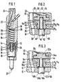
- FIG. 1 shows a longitudinal section through the first exemplary embodiment
- FIG. 2 enlarges a detail from FIG. 1
- FIG. 3 shows a variant for the embodiment according to FIGS. 1 and 2
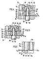
- FIGS. 4 and 5 each show the second and third exemplary embodiment on the basis of a sectional diagram corresponding to FIG
- FIG. 6 shows a variant of the third exemplary embodiment according to FIG. 5.
- the injection nozzle according to FIGS. 1 and 2 has a nozzle body 10 which, together with an intermediate disk 12, is clamped to a holding body 16 by means of a union nut 14.
- a valve needle 18 is slidably mounted in the nozzle body 10 and cooperates with an inward-facing valve seat in the nozzle body 10, which is arranged in front of a plurality of spray openings 20.
- the guide bore of the valve needle 18 is, as usual, expanded at one point to a pressure chamber, in the area of which the valve needle 18 has a pressure shoulder and which is connected via a channel 22 and a filter body 23 to a connecting piece 24 on the holding body 16 for connecting a fuel line.
- the fuel acting on the pressure shoulder of the valve needle 18 pushes the valve needle 18 upward against the graduated force curve of a closing force arrangement described below, the fuel being injected through the injection openings 20 in a pre-injection phase and a main injection phase.
- a chamber 26 for receiving a closing spring 28 is formed, which extends over a Washer 30 is supported on the bottom of chamber 26 and constantly acts on valve needle 18 via a pressure piece 32 and a pressure bolt 34 passing through washer 12.
- a piston 36 is tightly but displaceably mounted in the intermediate disk 12 and has two sections 38, 40 of different diameters, between which an annular shoulder 42 is formed.
- the correspondingly shaped bore in the intermediate disk 12 is provided with an annular shoulder 44 which delimits a second pressure chamber 46 on the piston 36 with the annular shoulder 42.
- the piston 36 rests with its lower end face 48 on the upper end face 50 of the nozzle body 10.
- the distance between the annular shoulders 42 and 44 corresponds to the total stroke hg reduced by a preliminary stroke h v and the distance between the end face 48 of the piston 36 and the flat, pinless end face 52 of the valve needle 18 in the closed position corresponds to the preliminary stroke h v .
- the pressure chamber 46 is connected to the channel 22 via a bore 54.
- the valve needle 18 first performs the preliminary stroke h v , in which the fuel in the pressure chamber of the nozzle body 10 only has to overcome the counterforce of the closing spring 28.
- the valve needle 18 abuts the piston 36, which stops the further movement of the valve needle 18 until the fuel pressure has risen so far that its force exerted on the valve needle in the opening direction acts on the force of the closing spring 28 and on the annular shoulder 42 hydraulic closing force exceeds.
- the valve needle 18 together with the piston 36 is moved upward until the annular shoulders 42, 44 come into contact with one another on the piston 36 and on the intermediate disk 12.
- the processes take place in reverse order.
- the arrangement described has the advantage that the additional piston 36 does not require any additional space in the longitudinal direction of the injection nozzle and that the residual stroke hg-h v of the valve needle 18 is influenced solely by the axial positional tolerances of the annular shoulder 42, 44 on the piston 36 and the intermediate disk 12 .
- the valve needle 18a is designed such that in its closed position the upper end face 52a lies in the plane of the upper end face 50 of the nozzle body 10, so that both parts can be finished together by one tool.
- the preliminary stroke play is obtained in this case in that an inner annular surface section 48a of the lower end face of the piston 36a is set back by the amount of the preliminary stroke h v compared to the remaining outer annular surface section 48b of this end face.
- the actual dimension of the forward stroke is only influenced by tolerances on the piston 36a, which are tool-related and can therefore be kept extremely small.
- the variant according to FIG. 3 differs from the embodiment according to FIGS. 1 and 2 in that the pressure pin 34a is integrally formed on the pressure element 32a.
- an externally and internally smooth-cylindrical piston bushing 58 is displaceably guided in a correspondingly shaped ring-cylindrical recess in the intermediate disc 56 in an intermediate disc 56.
- a pressure chamber 62 is formed in this recess above the upper end face 60 of the piston bushing 58 and is connected to the channel 22 via a bore 64. The fuel pressure in the pressure chamber 62 presses the piston bushing 58 against the upper end face 50 of the nozzle body 10, which lies above the upper end face 52 of the valve needle 18 by the amount of advance stroke h v .
- the inner diameter of the piston sleeve 58 is smaller than the diameter of the valve needle 18, so that the valve needle 18 abuts the lower end face 66 of the piston sleeve 58 after the advance stroke h v and takes it upward after the desired pressure level in the opening pressure profile of the fuel.
- the total stroke hg of the valve needle 18 is limited by the inner collar 68 of the intermediate disk 56, which surrounds the pressure pin 34 and is correspondingly set back relative to the lower end face of the intermediate disk 56.
- the injection nozzle according to FIG. 5 differs from that according to FIG. 4 essentially in that instead of the piston bushing 58, a ring of pin-like individual pistons 70 is provided, the guide bores of which open into an annular pressure chamber 72 at the top. This is formed by a corresponding recess in the upper end face of an intermediate disk 74, which is closed off by a cover plate 76 and is connected to the channel 22 via a groove 78.
- the individual pistons 70 perform the same function as the piston bushing 58 according to FIG. 4 and the total stroke hg of the valve needle 18 is also limited here by a recessed inner annular surface section 80 of the intermediate disk 74.
- the upper end face 52a of the valve needle 18a lies in its closed position in the plane of the upper end face 50 of the nozzle body 10.
- the individual pistons 70a with lugs 82 provided which in the lower end position of the individual pistons 70a rest on the end face 50 of the nozzle body 10 and hold the end face regions 84 of the individual pistons 70a projecting into the path of the valve needle 18a by the dimension h v above the end face 50.
- the measure taken in the variant according to FIG. 6 could also be provided in an equivalent form in the piston bushing 58 according to FIG. 4, for example by turning it in on its lower end face. It is thereby achieved that the upper end faces of the nozzle body 10 and nozzle needle 18 can also be machined there. If only two diametrically opposed individual pistons 70 and 70a are provided, the arrangement of a cover plate 76 can be dispensed with if the individual pistons 70 are to be received or 70a blind bores are provided, which are each offset by 90 ° relative to the channel 22 and are connected to these via individual bores.
Landscapes
- Engineering & Computer Science (AREA)
- Chemical & Material Sciences (AREA)
- Combustion & Propulsion (AREA)
- Mechanical Engineering (AREA)
- General Engineering & Computer Science (AREA)
- Fuel-Injection Apparatus (AREA)
Claims (10)
pression (46, 62, 72) étant prévue pour un dispositif de piston (36, 36a, 58, 70, 70a) sollicité par la pression d'alimentation du carburant dans le sens de la fermeture du pointeau de soupape (18, 18a) et pressé dans cette position de fermeture contre une première butée fixe (50), et contre lequel le pointeau de soupape (18, 18a) vient en butée après avoir parcouru une pré-course (hv), après quoi lors d'une nouvelle augmentation de la pression de carburant d'un échelon de pression prédéterminé, le pointeau de soupape (18, 18a) et le dispositif de piston (36, 36a, 58, 70, 70a) sont à nouveau déplacés jusqu'à une seconde butée fixe (44, 68, 80), injecteur caractérisé en ce que le dispositif de piston (36, 36a, 58, 70, 70a) exerçant un effort supplémentaire sur le pointeau de soupape (18, 18a) après que celui-ci est parcouru la pré-course (hv) est monté dans la rondelle intermédiaire (12, 56, 74) de façon à pouvoir coulisser, tandis que la seconde chambre de pression (46, 62, 72) est ménagée dans cette rondelle secondaire (12, 56, 74).
Applications Claiming Priority (2)
| Application Number | Priority Date | Filing Date | Title |
|---|---|---|---|
| DE3611316 | 1986-04-04 | ||
| DE19863611316 DE3611316A1 (de) | 1986-04-04 | 1986-04-04 | Kraftstoff-einspritzduese fuer brennkraftmaschinen |
Publications (2)
| Publication Number | Publication Date |
|---|---|
| EP0240693A1 EP0240693A1 (fr) | 1987-10-14 |
| EP0240693B1 true EP0240693B1 (fr) | 1990-12-27 |
Family
ID=6297927
Family Applications (1)
| Application Number | Title | Priority Date | Filing Date |
|---|---|---|---|
| EP87102772A Expired - Lifetime EP0240693B1 (fr) | 1986-04-04 | 1987-02-26 | Injecteur de combustible pour moteurs à combustion interne |
Country Status (3)
| Country | Link |
|---|---|
| EP (1) | EP0240693B1 (fr) |
| JP (1) | JPS62240466A (fr) |
| DE (2) | DE3611316A1 (fr) |
Cited By (1)
| Publication number | Priority date | Publication date | Assignee | Title |
|---|---|---|---|---|
| DE102013211658A1 (de) | 2012-07-12 | 2014-05-15 | Ford Global Technologies, Llc | Kraftstoff-Einspritzinjektor |
Families Citing this family (5)
| Publication number | Priority date | Publication date | Assignee | Title |
|---|---|---|---|---|
| GB8706757D0 (en) * | 1987-03-21 | 1987-04-23 | Lucas Ind Plc | Fuel injection nozzles |
| GB8824478D0 (en) * | 1988-10-19 | 1988-11-23 | Lucas Ind Plc | Fuel injection nozzle |
| JP2844742B2 (ja) * | 1989-11-13 | 1999-01-06 | 日産自動車株式会社 | ディーゼル機関の燃料噴射ノズル |
| DE4225805A1 (de) * | 1992-08-05 | 1994-02-10 | Bosch Gmbh Robert | Kraftstoff-Einspritzdüse für Brennkraftmaschinen |
| DE4408245A1 (de) * | 1994-03-11 | 1995-09-14 | Bosch Gmbh Robert | Einspritzdüse für Brennkraftmaschinen |
Family Cites Families (4)
| Publication number | Priority date | Publication date | Assignee | Title |
|---|---|---|---|---|
| GB1110102A (en) * | 1963-11-26 | 1968-04-18 | Ruston & Hornsby Ltd | Improvements in fuel injection equipment for internal combustion engines |
| US4167168A (en) * | 1976-02-05 | 1979-09-11 | Nippondenso Co., Ltd. | Fuel injection apparatus |
| DE2711902A1 (de) * | 1977-03-18 | 1978-09-21 | Bosch Gmbh Robert | Kraftstoffeinspritzduese |
| DE3041018C2 (de) * | 1980-10-31 | 1986-03-20 | Daimler-Benz Ag, 7000 Stuttgart | Kraftstoffeinspritzeinrichtung für eine luftverdichtende Einspritzbrennkraftmaschine |
-
1986
- 1986-04-04 DE DE19863611316 patent/DE3611316A1/de not_active Withdrawn
-
1987
- 1987-02-26 EP EP87102772A patent/EP0240693B1/fr not_active Expired - Lifetime
- 1987-02-26 DE DE8787102772T patent/DE3767001D1/de not_active Expired - Lifetime
- 1987-04-02 JP JP62079852A patent/JPS62240466A/ja active Pending
Cited By (2)
| Publication number | Priority date | Publication date | Assignee | Title |
|---|---|---|---|---|
| DE102013211658A1 (de) | 2012-07-12 | 2014-05-15 | Ford Global Technologies, Llc | Kraftstoff-Einspritzinjektor |
| US9605639B2 (en) | 2012-07-12 | 2017-03-28 | Ford Global Technologies, Llc | Fuel injector |
Also Published As
| Publication number | Publication date |
|---|---|
| JPS62240466A (ja) | 1987-10-21 |
| DE3611316A1 (de) | 1987-10-08 |
| DE3767001D1 (de) | 1991-02-07 |
| EP0240693A1 (fr) | 1987-10-14 |
Similar Documents
| Publication | Publication Date | Title |
|---|---|---|
| EP0282480B1 (fr) | Injecteur de carburant pour moteurs a combustion interne | |
| EP0133470B1 (fr) | Injecteur de carburant pour moteurs à combustion interne | |
| WO2008083881A1 (fr) | Injecteur pour injecter du carburant dans les chambres de combustion des moteurs à combustion interne | |
| DE19709794A1 (de) | Ventil zum Steuern von Flüssigkeiten | |
| EP1989436A1 (fr) | Dispositif d'injection de carburant pour moteur a combustion interne | |
| WO2005124153A1 (fr) | Pompe haute pression conçue pour un dispositif d'injection de carburant d'un moteur a combustion interne | |
| DE3228079A1 (de) | Kraftstoff-einspritzduese fuer brennkraftmaschinen | |
| EP0096312A1 (fr) | Injecteur de combustible pour moteurs à combustion interne | |
| EP0240693B1 (fr) | Injecteur de combustible pour moteurs à combustion interne | |
| DE10353045A1 (de) | Kraftstoffeinspritzventil | |
| EP1402174B1 (fr) | Dispositif d'injection de carburant pour moteur a combustion interne | |
| DE102004005451A1 (de) | Kraftstoffeinspritzsystem für Brennkraftmaschinen | |
| DE10205185A1 (de) | Kraftstoffeinspritzeinrichtung für eine Brennkraftmaschine | |
| EP0606436B1 (fr) | Injecteur de carburant pour moteurs a combustion interne | |
| EP1525390A1 (fr) | Dispositif d'injection de carburant pour moteur a combustion interne | |
| WO2003071124A1 (fr) | Dispositif d'injection de carburant d'un moteur a combustion interne | |
| DE3802136C2 (de) | Pumpedüse, insbesondere für direkt einspritzende Diesel-Brennkraftmaschinen | |
| DE3907569A1 (de) | Kraftstoff-einspritzduese fuer brennkraftmaschinen | |
| EP0445126B1 (fr) | Injecteur de carburant pour moteurs a combustion interne | |
| WO2002086307A1 (fr) | Dispositif d'injection de carburant pour moteur a combustion | |
| DE3839038A1 (de) | Kraftstoff-einspritzduese fuer brennkraftmaschinen | |
| DE10146745A1 (de) | Kraftstoffeinspritzeinrichtung für eine Brennkraftmaschine | |
| DE3819814A1 (de) | Kraftstoff-einspritzduese fuer brennkraftmaschinen | |
| DE3839812A1 (de) | Kraftstoff-einspritzduese fuer brennkraftmaschinen | |
| DE3701017A1 (de) | Kraftstoff-einspritzduese fuer brennkraftmaschinen |
Legal Events
| Date | Code | Title | Description |
|---|---|---|---|
| PUAI | Public reference made under article 153(3) epc to a published international application that has entered the european phase |
Free format text: ORIGINAL CODE: 0009012 |
|
| AK | Designated contracting states |
Kind code of ref document: A1 Designated state(s): DE FR GB IT |
|
| 17P | Request for examination filed |
Effective date: 19880324 |
|
| 17Q | First examination report despatched |
Effective date: 19880729 |
|
| GRAA | (expected) grant |
Free format text: ORIGINAL CODE: 0009210 |
|
| AK | Designated contracting states |
Kind code of ref document: B1 Designated state(s): DE FR GB IT |
|
| ET | Fr: translation filed | ||
| GBT | Gb: translation of ep patent filed (gb section 77(6)(a)/1977) | ||
| REF | Corresponds to: |
Ref document number: 3767001 Country of ref document: DE Date of ref document: 19910207 |
|
| ITTA | It: last paid annual fee | ||
| ITF | It: translation for a ep patent filed |
Owner name: STUDIO JAUMANN |
|
| PLBE | No opposition filed within time limit |
Free format text: ORIGINAL CODE: 0009261 |
|
| STAA | Information on the status of an ep patent application or granted ep patent |
Free format text: STATUS: NO OPPOSITION FILED WITHIN TIME LIMIT |
|
| 26N | No opposition filed | ||
| PGFP | Annual fee paid to national office [announced via postgrant information from national office to epo] |
Ref country code: GB Payment date: 19920214 Year of fee payment: 6 |
|
| PGFP | Annual fee paid to national office [announced via postgrant information from national office to epo] |
Ref country code: FR Payment date: 19920227 Year of fee payment: 6 |
|
| PGFP | Annual fee paid to national office [announced via postgrant information from national office to epo] |
Ref country code: DE Payment date: 19920423 Year of fee payment: 6 |
|
| PG25 | Lapsed in a contracting state [announced via postgrant information from national office to epo] |
Ref country code: GB Effective date: 19930226 |
|
| GBPC | Gb: european patent ceased through non-payment of renewal fee |
Effective date: 19930226 |
|
| PG25 | Lapsed in a contracting state [announced via postgrant information from national office to epo] |
Ref country code: FR Effective date: 19931029 |
|
| PG25 | Lapsed in a contracting state [announced via postgrant information from national office to epo] |
Ref country code: DE Effective date: 19931103 |
|
| REG | Reference to a national code |
Ref country code: FR Ref legal event code: ST |
|
| PG25 | Lapsed in a contracting state [announced via postgrant information from national office to epo] |
Ref country code: IT Free format text: LAPSE BECAUSE OF NON-PAYMENT OF DUE FEES;WARNING: LAPSES OF ITALIAN PATENTS WITH EFFECTIVE DATE BEFORE 2007 MAY HAVE OCCURRED AT ANY TIME BEFORE 2007. THE CORRECT EFFECTIVE DATE MAY BE DIFFERENT FROM THE ONE RECORDED. Effective date: 20050226 |