EP0240130A1 - Vorrichtung und Verfahren zur Beseitigung von Schlackengraten von einem Werkstück - Google Patents
Vorrichtung und Verfahren zur Beseitigung von Schlackengraten von einem Werkstück Download PDFInfo
- Publication number
- EP0240130A1 EP0240130A1 EP87301501A EP87301501A EP0240130A1 EP 0240130 A1 EP0240130 A1 EP 0240130A1 EP 87301501 A EP87301501 A EP 87301501A EP 87301501 A EP87301501 A EP 87301501A EP 0240130 A1 EP0240130 A1 EP 0240130A1
- Authority
- EP
- European Patent Office
- Prior art keywords
- workpiece
- cutting
- blade
- cutting blade
- cutting edge
- Prior art date
- Legal status (The legal status is an assumption and is not a legal conclusion. Google has not performed a legal analysis and makes no representation as to the accuracy of the status listed.)
- Granted
Links
- 238000000034 method Methods 0.000 title claims abstract description 29
- 239000002184 metal Substances 0.000 title claims abstract description 27
- 229910052751 metal Inorganic materials 0.000 title claims abstract description 27
- 238000005520 cutting process Methods 0.000 claims abstract description 248
- 230000007935 neutral effect Effects 0.000 claims description 15
- 238000012544 monitoring process Methods 0.000 claims description 3
- 230000009471 action Effects 0.000 claims description 2
- 229910000831 Steel Inorganic materials 0.000 description 6
- 230000008569 process Effects 0.000 description 6
- 239000002893 slag Substances 0.000 description 6
- 239000010959 steel Substances 0.000 description 6
- QVGXLLKOCUKJST-UHFFFAOYSA-N atomic oxygen Chemical compound [O] QVGXLLKOCUKJST-UHFFFAOYSA-N 0.000 description 5
- 238000005266 casting Methods 0.000 description 5
- 229910052760 oxygen Inorganic materials 0.000 description 5
- 239000001301 oxygen Substances 0.000 description 5
- 238000012360 testing method Methods 0.000 description 5
- XEEYBQQBJWHFJM-UHFFFAOYSA-N Iron Chemical compound [Fe] XEEYBQQBJWHFJM-UHFFFAOYSA-N 0.000 description 4
- 238000009825 accumulation Methods 0.000 description 4
- 238000010276 construction Methods 0.000 description 4
- 230000004048 modification Effects 0.000 description 4
- 238000012986 modification Methods 0.000 description 4
- 238000009749 continuous casting Methods 0.000 description 3
- 238000005096 rolling process Methods 0.000 description 3
- UQSXHKLRYXJYBZ-UHFFFAOYSA-N Iron oxide Chemical compound [Fe]=O UQSXHKLRYXJYBZ-UHFFFAOYSA-N 0.000 description 2
- 230000005540 biological transmission Effects 0.000 description 2
- 230000015572 biosynthetic process Effects 0.000 description 2
- 238000001816 cooling Methods 0.000 description 2
- 238000005755 formation reaction Methods 0.000 description 2
- 229910052742 iron Inorganic materials 0.000 description 2
- 239000000463 material Substances 0.000 description 2
- 230000007246 mechanism Effects 0.000 description 2
- 238000012545 processing Methods 0.000 description 2
- 239000002699 waste material Substances 0.000 description 2
- OKTJSMMVPCPJKN-UHFFFAOYSA-N Carbon Chemical compound [C] OKTJSMMVPCPJKN-UHFFFAOYSA-N 0.000 description 1
- 230000001154 acute effect Effects 0.000 description 1
- 239000000956 alloy Substances 0.000 description 1
- 229910045601 alloy Inorganic materials 0.000 description 1
- 230000004075 alteration Effects 0.000 description 1
- 229910052799 carbon Inorganic materials 0.000 description 1
- 238000006243 chemical reaction Methods 0.000 description 1
- 238000013461 design Methods 0.000 description 1
- 238000010586 diagram Methods 0.000 description 1
- 230000000694 effects Effects 0.000 description 1
- QFXZANXYUCUTQH-UHFFFAOYSA-N ethynol Chemical group OC#C QFXZANXYUCUTQH-UHFFFAOYSA-N 0.000 description 1
- 239000012530 fluid Substances 0.000 description 1
- 238000012423 maintenance Methods 0.000 description 1
- 238000004519 manufacturing process Methods 0.000 description 1
- 238000005058 metal casting Methods 0.000 description 1
- 238000003303 reheating Methods 0.000 description 1
- 230000004044 response Effects 0.000 description 1
Images



Classifications
-
- B—PERFORMING OPERATIONS; TRANSPORTING
- B23—MACHINE TOOLS; METAL-WORKING NOT OTHERWISE PROVIDED FOR
- B23K—SOLDERING OR UNSOLDERING; WELDING; CLADDING OR PLATING BY SOLDERING OR WELDING; CUTTING BY APPLYING HEAT LOCALLY, e.g. FLAME CUTTING; WORKING BY LASER BEAM
- B23K7/00—Cutting, scarfing, or desurfacing by applying flames
-
- B—PERFORMING OPERATIONS; TRANSPORTING
- B22—CASTING; POWDER METALLURGY
- B22D—CASTING OF METALS; CASTING OF OTHER SUBSTANCES BY THE SAME PROCESSES OR DEVICES
- B22D11/00—Continuous casting of metals, i.e. casting in indefinite lengths
- B22D11/12—Accessories for subsequent treating or working cast stock in situ
- B22D11/126—Accessories for subsequent treating or working cast stock in situ for cutting
- B22D11/1265—Accessories for subsequent treating or working cast stock in situ for cutting having auxiliary devices for deburring
-
- B—PERFORMING OPERATIONS; TRANSPORTING
- B23—MACHINE TOOLS; METAL-WORKING NOT OTHERWISE PROVIDED FOR
- B23D—PLANING; SLOTTING; SHEARING; BROACHING; SAWING; FILING; SCRAPING; LIKE OPERATIONS FOR WORKING METAL BY REMOVING MATERIAL, NOT OTHERWISE PROVIDED FOR
- B23D1/00—Planing or slotting machines cutting by relative movement of the tool and workpiece in a horizontal straight line only
- B23D1/20—Planing or slotting machines cutting by relative movement of the tool and workpiece in a horizontal straight line only with tool-supports or work-supports specially mounted or guided for working in different directions or at different angles; Special purpose machines
- B23D1/22—Planing or slotting machines cutting by relative movement of the tool and workpiece in a horizontal straight line only with tool-supports or work-supports specially mounted or guided for working in different directions or at different angles; Special purpose machines for planing ingots or the like
-
- Y—GENERAL TAGGING OF NEW TECHNOLOGICAL DEVELOPMENTS; GENERAL TAGGING OF CROSS-SECTIONAL TECHNOLOGIES SPANNING OVER SEVERAL SECTIONS OF THE IPC; TECHNICAL SUBJECTS COVERED BY FORMER USPC CROSS-REFERENCE ART COLLECTIONS [XRACs] AND DIGESTS
- Y10—TECHNICAL SUBJECTS COVERED BY FORMER USPC
- Y10T—TECHNICAL SUBJECTS COVERED BY FORMER US CLASSIFICATION
- Y10T409/00—Gear cutting, milling, or planing
- Y10T409/50—Planing
- Y10T409/50082—Process
-
- Y—GENERAL TAGGING OF NEW TECHNOLOGICAL DEVELOPMENTS; GENERAL TAGGING OF CROSS-SECTIONAL TECHNOLOGIES SPANNING OVER SEVERAL SECTIONS OF THE IPC; TECHNICAL SUBJECTS COVERED BY FORMER USPC CROSS-REFERENCE ART COLLECTIONS [XRACs] AND DIGESTS
- Y10—TECHNICAL SUBJECTS COVERED BY FORMER USPC
- Y10T—TECHNICAL SUBJECTS COVERED BY FORMER US CLASSIFICATION
- Y10T409/00—Gear cutting, milling, or planing
- Y10T409/50—Planing
- Y10T409/501476—Means to remove flash or burr
- Y10T409/50164—Elongated work
- Y10T409/501968—Transverse burr
-
- Y—GENERAL TAGGING OF NEW TECHNOLOGICAL DEVELOPMENTS; GENERAL TAGGING OF CROSS-SECTIONAL TECHNOLOGIES SPANNING OVER SEVERAL SECTIONS OF THE IPC; TECHNICAL SUBJECTS COVERED BY FORMER USPC CROSS-REFERENCE ART COLLECTIONS [XRACs] AND DIGESTS
- Y10—TECHNICAL SUBJECTS COVERED BY FORMER USPC
- Y10T—TECHNICAL SUBJECTS COVERED BY FORMER US CLASSIFICATION
- Y10T409/00—Gear cutting, milling, or planing
- Y10T409/50—Planing
- Y10T409/509348—Tool head
- Y10T409/509676—Tool head with means to permit repositioning of cutting for idle return stroke
- Y10T409/50984—Tool head with means to permit repositioning of cutting for idle return stroke comprising pivotable cutter or cutter support
Definitions
- the present invention relates to an apparatus and method for removing dross ridges from metal workpieces, such as slabs, blooms, billets, or the like.
- the continuous cast length emerging from the caster is cut into desired lengths to form separate metal workpieces, which are commonly referred to as slabs, blooms, or billets.
- the separate workpieces are then subjected to subsequent processing, as by rolling, to form a finished steel product.
- the cutting operation as described above is conventionally performed by means of a flame or torch, wherein a jet of high purity oxygen is directed against the workpiece while it is heated.to the oxygen ignition temperature.
- the resulting exothermic chemical reaction between the iron and oxygen produces slag or waste, which consists of iron oxide, metallic iron and other alloy elements.
- This slag or waste is in the molten state, and it is displaced during the cutting operation and a portion thereof forms a ridge of the material along the lower edge of the cut end.
- the material solidifies and adheres to the workpiece surface along the bottom surface adjacent the cut end, and forms what is commonly called a "dross ridge".
- dross ridges on the workpiece presents problems in the further processing thereof.
- a dross ridge may drop off in the reheat furnace, which requires that it then be removed, thus involving additional labor.
- the dross ridge remains adhered to the workpiece during reheating, it is laminated into the steel during rolling of the workpiece, resulting in an inferior product.
- U.S. patent No. 2,301,923 suggests a process for dross removal which involves immediately cooling the slag as it emerges from the cut, and so that it rapidly solidifies and may be easily removed by a subsequent mechanical operation.
- This prior patent also states that it has been previously proposed to remove such slag formations from a hot workpiece by means of a shear, but it is indicated that this prior proposal was not entirely satisfactory since the shear was subject to slag accumulation due to its hot condition.
- an apparatus and method which includes a cutting blade having an outer surface and at least one lengthwise extending side, and with the one side defining a lengthwise extending cutting edge at the junction of the side and the outer surface.
- the cutting blade is mounted for pivotal movement about a lengthwise axis, and such that the blade is adapted to be mounted immediately adjacent the path of travel of a metal workpiece supported by a conveyor system, and with the lengthwise direction of the blade extending across the workpiece path of travel.
- Means are also provided for pivoting the cutting blade about the lengthwise axis, and so that the cutting edge may be held in contact with the adjacent surface of the workpiece moving along the path of travel.
- the cutting edge is adapted to engage and remove a dross ridge formed on the adjacent workpiece surface when the workpiece is moved along the path of travel in a direction opposing the cutting edge.
- the outer surface of the cutting blade is generally flat, and the blade includes a second lengthwise extending side, which is opposite and parallel to the first mentioned side.
- the second side and the outer surface also define a second lengthwise extending cutting edge at the junction of the second side and the outer surface.
- the pivoting means is designed to selectively pivot the cutting blade about the lengthwise axis, and such that the blade may be pivoted to a neutral position wherein the outer surface is parallel to and spaced from the surface of a workpiece advancing along the path of travel, to a first tilted position wherein one of the cutting edges is adapted to engage the adjacent surface of the workpiece, and to a second oppositely tilted position wherein the other of the cutting edges is adapted to engage the surface of the adjacent workpiece.
- each cutting edge is adapted to engage and remove a dross ridge formed on the workpiece surface when the workpiece is moved along the path of travel in a direction opposing such cutting edge.
- the means for advancing the metal workpiece along its path of travel is adapted to advance the workpiece in each direction, and so that dross ridges formed at the opposite ends of the workpiece may each be removed.
- the above described embodiment of the present invention may be mounted in a metal workpiece conveying line, either on existing conveyor roll foundations or on a separate foundation, and with the horizontal or neutral position of the cutting blade being slightly below the pass line of the lower surface of the metal workpiece.
- a workpiece having a dross ridge along its lower surface at each end is passed over the cutting blade, while the blade is in its neutral position.
- the blade is then tilted so that the cutting edge which faces the trailing end of the workpiece is raised into contact with the surface of the workpiece, and so that the raised cutting edge engages and shears the dross ridge adjacent the trailing end.
- the method may be performed by terminating the advance of the workpiece after the leading end passes the cutting blade.
- the advance of the workpiece is then reversed, and the blade is tilted so that one of the cutting edges engages the surface of the workpiece and then engages and removes the dross ridge at the leading end of the workpiece.
- the advance of the workpiece is again reversed to its original direction, and the blade is tilted to its opposite position so that the opposite cutting edge engages and removes the dross ridge at the trailing end of the workpiece.
- the apparatus comprises a workpiece support means having opposite ends and opposite side edges, and defining an elongate longitudinal direction between the ends, and a traverse direction between the side edges.
- the apparatus also includes workpiece transport means for moving a metal workpiece supported on the support means in opposite transverse directions.
- Cutting blade means extend along each side edge of the support means, with each cutting blade means having an outer surface and a longitudinally extending side, and with the junction of the outer surface and the side defining a longitudinally extending cutting edge.
- Means are also provided for separately mounting each of the cutting blade means for separate pivotal movement about a longitudinal axis which is spaced from said cutting edge, and with the cutting edges thereof facing outwardly from the support means, and means are provided for separately pivoting each of the cutting blade means about its associated longitudinal pivotal axis and so that each cutting edge may be held in contact with the adjacent surface of a workpiece moving transversely across the support means, and such that each cutting blade means is adapted to engage and remove a dross ridge formed on the adjacent workpiece surface when the workpiece is moved transversely across the support means with the dross ridge disposed substantially parallel to the longitudinal direction and opposing the cutting edge.
- the workpiece transport means preferably includes means for also longitudinally moving the metal workpiece in opposite longitudinal directions along the support means, and the apparatus further comprises a transverse cutting blade extending transversely across the support means adjacent each of the ends of the apparatus, with the transverse cutting blades being of similar construction as compared to the side edge cutting blade means, and being adapted to remove dross ridges at the longitudinal ends of the workpiece.
- the apparatus and method of the present invention are adapted to remove dross ridges from a hot metal workpiece, i.e., at its casting or rolling temperature, or at ambient temperature. Also, the dross ridge which is sheared from the surface of the workpiece tends to drop off, and there is no substantial buildup or accumulation thereof on the cutting blade, and the cutting blade remains relatively cool when operating on a hot workpiece since there is little surface contact between the blade and workpiece.
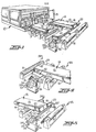
- Figure 1 illustrates a conventional steel casting machine 10, of a type which is adapted to form two parallel continuous castings 12, 12'.
- An oxygen cutting torch 13 is mounted at the downstream end of each output line, to cut the castings into separate slabs, blooms, or billets, which are referred to herein as workpieces 14.
- each workpiece 14 has an upper surface 15, a lower surface 16, a leading end 18, and a trailing end 18'.
- the workpiece includes a dross ridge 17, 17' formed on the lower surface adjacent the leading end 18 and the trailing end 18' of the workpiece, respectively.
- the apparatus includes conveyor means in the form of a series of driven conveyor rolls 19, for advancing each workpiece along a horizontal path of travel, with the direction of the advance being such that the ends 18, 18' and the dross ridges 17, 17' are disposed perpendicular to the path of travel.
- this orientation may not be exactly perpendicular, since the torches 13 may be set to cut the workpieces at the angle, or the workpieces may shift on the rolls 19.
- the conveyor rolls 19 are adapted to selectively advance each workpiece in opposite directions along a horizontal path of travel, and in the manner further described below.
- the apparatus of the present invention further comprises a cutting blade 20 mounted transversely across and below the path of travel of each workpiece 14.
- Each cutting blade 20 comprises a generally flat outer or top surface 21, which has a rectangular configuration in plan, and the blade includes opposite sides 22, 23 and opposite ends 25, 26 which define a lengthwise direction therebetween. The length of the blade is somewhat greater than the width of the workpiece being processed.
- the opposite sides 22, 23 each form an acute angle A with respect to the outer surface (note Figure 5) with the angle A preferably being in the range from about 25° to 60°.
- the side 22 thus defines a longitudinally extending straight first cutting edge 28 at the junction of the side 22 and the outer surface 21, and the side 23 defines an opposite longitudinally extending straight cutting edge 29 at the junction of the side 23 and the outer surface 21.
- the cutting blade 20 is mounted for pivotal movement about a lengthwise axis which is spaced from and parallel to each of the cutting edges 28 and 29. Also, the cutting blade is positioned immediately adjacent and below the workpiece path of travel, and such that the lengthwise pivotal axis of the cutting blade extends across the path of travel.
- This mounting means includes a support member 30 which underlies substantially the full area of the blade, and the support member includes stub shafts 31, 31' projecting from the opposite ends thereof and which are coaxially disposed along the lengthwise pivotal axis of the blade.
- a pillow block bearing 32 journals the stub shaft 31, and a similar bearing 32' is provided for the shaft 31'.
- the stub shaft 31 extends through its support bearing and carries a lever arm 34, the arm 34 being held by a key (not shown) for rotation with the shaft 31.
- the key may be in the form of a shear pin which serves to prevent damage to the apparatus or workpiece in the event of an accidental collision with the apparatus.
- Connected to the outer end of the lever arm 34 is a movable piston rod end of a hydraulic cylinder 36.
- the base of the cylinder 36 is connected by a pin to a suitable foundation, with the foundation also mounting the bearing blocks 32, 32'.
- the apparatus of the present invention further includes means for selectively pivoting the cutting blade about the lengthwise axis defined by the shafts 31, 31', and such that the blade may be selectively pivoted to a neutral position as shown in Figure 1 and wherein the outer surface 21 of the cutting blade 20 is parallel to and spaced from the adjacent surface 16 of the workpiece 14 advancing along the path of travel.
- the blade 20 may also be pivoted to a first tilted position ( Figure 3) wherein the cutting edge 28 is adapted - to engage the adjacent surface 16 of the workpiece, and to a second oppositely tilted position (Figure 2) wherein the cutting edge 29 is adapted to engage the surface 16 of the workpiece.
- This pivoting means for the cutting blade is illustrated schematically in Figure 8.
- a hydraulic pump 40 driven by a motor 41 which provides the motive fluid through a pressure relief valve 42 to a solenoid actuated four-way valve 44 for the hydraulic cylinder 36.
- a holding valve 45 is provided between the four-way valve 44 and the cylinder 36, and a first switch 47 is provided for actuating the pump motor 41, and a second switch 48 energizes the solenoid valve control circuits.
- indicator lights 49 and 50 are also controlled by the switches 47 and 48, respectively.
- the control of the solenoid valve 44 is by means of a switch 52, which in turn is operatively connected to the central control 53.
- the switches 47, 48, and 52 may be manually activated.
- control means further includes a pair of workpiece position sensors located adjacent the workpiece path of travel, as indicated schematically at 54, 55 in Figures 2, 3 and 4. Also, there is provided a position indicator 56 mounted on the shaft 31 of the cutting blade, and two sensors 58, 59 are fixedly mounted adjacent the indicator 56 for monitoring the rotational position of the blade. These four sensors, 54, 55,.58 and 59 are operatively connected to the central control 53 of the apparatus, and the central control 53 is adapted to operate the workpiece advance drive 60 for the rolls 19, in response to signals from these four sensors and as schematically indicated in Figure 8.
- the cutting blade 20 is mounted such that its lengthwise pivotal axis extends across the path of travel of the workpiece 14. While the blade can extend so that its lengthwise axis, and thus the cutting edges 28, 29 are exactly perpendicular to the path of travel, is it preferable for the cutting edges to be disposed at an angle of at least about one degree with respect to a line which is perpendicular to the workpiece path of travel, and thus also with respect to the ends 18, 18' and dross ridges 17, 17'. Preferably, the cutting edges 28, 29 are disposed at an angle of between about 1 to 15 ° with respect to a line which is perpendicular to the path of travel, note angle B in Figure 7.
- the surface 21 of the blade In its neutral position, the surface 21 of the blade is slightly below a plane lying tangent to the upper surfaces of the conveyor rolls 19, and which corresponds to the location of the lower surface 16 of the workpiece, with a clearance of approximately one half to one inch being provided between the outer surface 21 of the blade and the conveyor plane.
- the cutting blade is sized and mounted such that the outer surface is at an angle C of at least about 1° and preferably about 10° with respect to the adjacent surface 16 of the workpiece in each of its two tilted positions, note Figure 5.
- the tilt of the blade should not be so great as to cause the cutting edge to dig into or scrape the bottom surface of the work piece, nor should the tilt be so shallow that the blade tends to jump over the dross ridge rather than engage and shear it off.
- Figures 1-3 illustrate one embodiment of the method of the present invention.
- the workpiece 14 is advanced by the conveyor rolls 19, and after the leading end 18 of the workpiece passes the blade 20, the blade is tilted so that the cutting edge 29 which opposes the dross ridge 17' at the trailing end of the workpiece is tilted into contact with the lower surface of the workpiece.
- the cutting edge 29 engages and removes the dross ridge 17' at the trailing end.
- the workpiece advance is reversed, and the blade is returned to its neutral position.
- the blade is then tilted in the opposite direction so that the cutting edge 28 engages the bottom surface of the workpiece, and continued movement of the workpiece in the reverse direction causes the cutting edge 29 to engage and remove the dross ridge 17.
- the advance of the workpiece is then again stopped and reversed so that it advances in the forward direction, and the blade is tilted to its neutral position where it awaits the next workpiece.
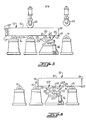
- FIG 4 schematically illustrates a different embodiment of the method of the present invention.
- the workpiece 14 is advanced in the forward direction until it spans the cutting blade (Steps 1 and 2).
- the sensor 55 is then activated, which acts through the central control 53 to stop the advance of the workpiece and to actuate the hydraulic cylinder 36 so as to pivot the blade and bring the forward cutting edge 28 into contact with the bottom surface of the workpiece (Step 3).
- the conveyor drive is then reversed (Step 4), moving the workpiece rearwardly, with the result that the cutting edge 28 engages and shears the dross ridge 17 at the forward end 18 of the workpiece (Step 5).
- the conveyor drive is again stopped when the sensor 59 senses the blade has rotated past the plane of the lower surface 16 and thus past the forward end of the workpeice, and the blade is returned to its neutral position (Step 7), as determined by the sensors 58, 59.
- the workpiece is then again moved forwardly (Step 8), so as to position the workpiece across the blade.
- the blade is pivoted or tilted to bring the trailing cutting edge 29 into contact with the lower surface of the workpiece (Step 9), so that the cutting edge 29 engages the downstream dross ridge 17' to remove the same (Step 10).
- the cutting blade is then returned to its neutral position (Steps 11 and 12), as determined by the sensors 58 and 59.
- Additional blade monitoring sensors may be provided, in order to permit the more accurate sensing of five positions of the blade, namely (1) the neutral position, (2) a forwardly tilted position in contact with the surface 16, (3) a maximum forwardly tilted position, (4) a reversely tilted position in contact with the lower surface 16, and (5) a maximum reversely tilted position.
- the dross removal apparatus of the present invention can be used to remove dross ridges from torch or flame cut workpieces having a wide range of sizes and shapes, and the cutting blade may be modified to accept curved or round workpieces as well.
- Figure 5 illustrates a modification of the present invention and which includes pinch rolls 62 and 63, which are provided to support the workpiece relative to the blade 20, and which serve to prevent the lifting of the workpiece upon impact of a dross ridge with a cutting edge of the blade.
- Any conventional pinch roll construction may be used, and conventional drive means may be associated with the pinch rolls if desired to provide a positive advancing force to the workpiece as it moves across the blade and to prevent stalling of the workpiece when the blade contacts a dross ridge.
- FIG. 6 Another modification of the present invention is illustrated in Figure 6, wherein an idler support roller 64 is incorporated in the cutting blade to provide support for the workpiece.
- the idler support roller 64 is rotatably mounted to the support member 30, and it includes an outer surface portion which is coplanar with the upper surfaces of the rolls 19 when the blade 20 is pivoted to its neutral position as seen in Figure 6.
- this modification is particularly suitable in cases where the workpiece may not be long enough to be adequately supported by the other support rolls 19 while it is advanced over the cutting blade 20.
- the axis of the idler support roller 64 is mounted so as to be perpendicular to the workpiece path of travel, and thus when the pivoted axis of the blade 20 is disposed at the angle B' with respect to a line perpendicular to the path of travel as seen in Figure 7A, the axis of the roller 64 is disposed at the same angle B' with respect to the axis of the blade 20.
- Figure 6 also illustrates a modification of the cutting blade, and wherein the cutting blade is defined by a separate elements 20', 20" which include the cutting edges 28, 29, and which are releasably attached to the support member 30 to facilitate replacement thereof.
- a conventional "skid" or the like may be used as the supporting or conveying arrangement for the metal workpiece, and that conventional driven rolls, slab shifters, pusher rods or the like may be used to provide the advancing means for the workpiece.
- the dross removal apparatus of the present invention can also be used to remove dross ridges from the upper surface of a workpiece, by simply turning the workpiece over and mounting the cutting blade 20 in an inverted position above the workpiece. Also, the apparatus may remove dross ridges from cut sides of a workpiece, in addition to the cut ends, by having the cutting blade positioned squarely or obliquely with respect to the dross ridge along the cut side of the workpiece.
- the cutting blade When known, automatic controls and sensing means are used with the dross removal apparatus of the invention, the cutting blade may be tilted from the horizontal or neutral position and to a tilted position where it is adapted to be engaged by the end of the advancing workpiece, to thereby serve as a means for locating the end of a new workpiece relative to the cutting blade.
- the cutting blade may then be tilted to the neutral position, permitting the dross ridge on the lower surface of the workpiece to pass over the cutting blade and so that the workpiece may overlie the cutting blade in accordance with the practice of the present invention as described above.
- a series of dross removal tests were run on low carbon, steel plate workpieces in the following manner.
- a cutting blade was provided which was similar to that shown in Figures 1-3, and which was one inch thick, six inches wide, and 32 inches in length.
- the blade was mounted so that its top surface formed an angle C of 10° with the bottom surface of the workpieces when tilted, and the blade had a cutting edge angle A of about 38°.
- the workpieces were at ambient temperature, and were 10 inches thick, 22 inches wide, and 30 inches long, and the workpieces were cut across their width using a conventional oxy-acetylene cutting torch.
- the workpieces were supported on a roller conveyor table during each test, and they were pushed across the cutting blade by a hydraulic cylinder, mounted perpendicularly to the cut edge.
- the hydraulic cylinder had a bore of about 2 and 1/2 inches and pressure gauge mounted thereon.
- the dross removal blade was set with the cutting edge of the blade parallel to the torch cut ends of the workpiece, and in a second series of tests the cutting edge was set at a five degree angle to the torch cut ends.
- the dross removal apparatus of the invention is able to remove dross from the torch cut ends of a metal workpiece with the blade parallel or angled with respect to the torch cut ends.
- the force required to remove a typical dross accumulation with the dross removal apparatus can be greatly reduced by angling the blade with respect to the torch cut ends.
- Figures 9 and 10 illustrate a further embodiment of a dross ridge removal apparatus, and which is generally indicated at 110.
- the apparatus 110 is adapted to be used in association with a conventional steel casting machine, as shown in Figure 1.
- the oxygen cutting torches which serve to cut the continuous casting into separate slabs, blooms, or billets, also, commonly cut the castings along their longitudinal length, and thus the resulting workpiece may have a dross ridge along each end and along one or both sides.
- a workpiece of the described type is illustrated at 112, and it is of rectangular, block-like configuration, having.parallel upper and lower surfaces 113, 114, opposite ends 115, 116, and opposite sides 117, 118.
- a dross ridge is formed along each end as indicated at 115' and 116' respectively (note Figure 15)and a dross ridge is also formed along each side as indicated at 117' and 118' respectively (note Figure 14).
- the apparatus 110 includes horizontal work support table 120 which is designed to receive workpiece 112 from the caster, with the workpiece being placed on the support table 120 by means of an overhead crane or the like. Also, the workpiece support table 120 includes opposite ends 122, 123 and opposite side edges 124, 125 and thus the apparatus defines an elongate longitudinal direction between the ends, and a shorter transverse direction between the side edges.
- the support table 120 is composed of a framework of vertically disposed plates 128, which are interconnected along each side by a guide rail 129. Also, the vertical plates 128 have a horizontal upper edge surface 130, with the upper edge surfaces 130 of the several plates defining a horizontal and planer support surface for the workpieces.
- the apparatus 110 also includes workpiece transport devices 132, 133 adjacent respective ends 122, 123, for moving the workpiece in opposite transverse directions, as well as in opposite longitudinal directions. More particularly, each workpiece transport device 132, 133 includes a frame 135 mounted for longitudinal movement along the apparatus by means of wheels 136 which are received in the longitudinal guide rails 129. Two separate drives are provided for longitudinally moving the two devices in the longitudinal directions. More particularly, the drive for the transport device 132 includes a drive motor 138 at the end 122 of the apparatus as seen in Figures 9 and 10, and the drive motor 138 acts through a suitable transmission 139 to rotate a pair of drive screws 140 which extend longitudinally along respective sides of the apparatus for about one-half its longitudinal length.
- Each drive screw 140 is threadedly connected to a drive nut 141 which is fixed to the transport device 132, and thus each side of the transport device 132 is positively driven.
- a similar drive motor and transmission are mounted adjacent the other end 123 of the apparatus for rotatably driving the pair of drive screws which 142 are associated with the other transport device 133 in a similar manner.
- the two transport devices 132, 133 may be selectively moved toward or away from each other in the longitudinal direction, or they may be moved together in the same longitudinal direction.
- Each of the transport devices 132, 133 also includes a pair of transversely movable gripper arms, 144, 145, which are adapted to move toward and away from each other so as to engage the sides of the workpiece 112, note Figure 13.
- the gripper arms 144, 145 are also adapted to move together in the transverse direction so that the workpiece can be moved in opposite transverse directions.
- the drive mechanism for moving the gripper .arms 144, 145 in this fashion is of conventional design, and is thus not specifically illustrated herein.
- the drive mechanism may be composed of a first drive and lead screw for opening and closing the arms 144, 145, and a second drive for transversely moving an assembly which mounts both arms and the first drive and lead screw.
- the apparatus 110 further includes longitudinal cutting blade means 148, 149 extending along each side edge of the support table 120. More particularly, each cutting blade means 148, 149 comprises a plurality of separate blades 150 which are aligned along the associated side edge of the support table. Each blade 150 has an outer flat surface 151 and an outer side 152, and so as to define a longitudinally extending cutting edge 153 at the junction of the side and the outer surface. Each of the blades 150 on each of the sides of the apparatus is mounted for separate pivotal movement about a common longitudinal axis 156 or 157 ( Figure 13), which is spaced inwardly from the cutting edge 153. Also, each of the cutting blades 150 is biased by a spring 158 so as to pivot the blade upwardly about the pivotal axis.
- an abutment 160 is fixed to one of the plates 128 adjacent each blade for limiting such pivotal movement from the action of the spring to a predetermined position wherein the generally flat outer surface 151 of the blade intersects the plane of the support surface, and such that the associated cutting edge 153 is on the side of such plane opposite its pivotal axis.
- the angle A ( Figure 14) between the flat outer surface 151 of the blade and the plane of the support surface should be between about 0 to 30 degrees when the cutting blade is at the predetermined position as defined by the abutment, and preferably, the angle A is about 3-4 degrees.
- the apparatus 110 further includes a first transverse cutting blade 162 which extends transversely across the support table along the end 122 thereof, and a second transverse cutting blade 163 which extends transversely across the support table along the other end 123 thereof.
- the first and second transverse cutting blades are of like construction, and the second transverse cutting blade 163 is illustrated in Figures 15 and 16. More particularly, the second blade 163 comprises a generally flat outer surface 165 and a straight side 166, with the junction of the side 166 and the outer surface 165 defining a straight cutting edge 167.
- the cutting blade 163 is mounted for pivotal movement about a transverse axis 168, which is spaced from and parallel to the cutting edge thereof, and means in the form of a spring 169 is provided for pivoting the cutting blade 163 about the pivotal axis 168.
- the outer surface intersects the plane of the support surface by the angle A', which is preferably the same magnitude as the angle A described above.
- the blade 163 is adapted to be pivoted downwardly by the workpiece moving thereacross to the solid line position as shown in Figure 15, and the cutting edge of the blade will be held in contact with the adjacent surface 114 of a workpiece 112 by the spring 169.
- the cutting edge is adapted to engage and remove a dross ridge 116' formed on the adjacent workpiece surface when the workpiece is moved in the direction which opposes the cutting edge and as seen in Figure 16.
- the transport devices 132, 133 are next moved together so as to move the workpiece longitudinally, and until the end of the workpiece moves across the transverse cutting blade 163 as seen in Figure 15.
- the advance of the workpiece is then terminated and reversed, so that the cutting edge 167 of the blade 163 engages and removes the dross ridge 116' at the end 116 of the workpiece, as seen in Figure 16.
- the transport devices 132, 133 move the workpiece longitudinally to the other end 122 of the table, and the process is repeated with respect to the transverse blade 162 and so as to remove the dross ridge 115' at the end 115 of the workpiece.
Landscapes
- Engineering & Computer Science (AREA)
- Mechanical Engineering (AREA)
- Arc Welding In General (AREA)
- Laser Beam Processing (AREA)
- Electrical Discharge Machining, Electrochemical Machining, And Combined Machining (AREA)
- Shearing Machines (AREA)
- Coating With Molten Metal (AREA)
- Furnace Details (AREA)
- Milling, Broaching, Filing, Reaming, And Others (AREA)
- Furnace Charging Or Discharging (AREA)
Priority Applications (1)
| Application Number | Priority Date | Filing Date | Title |
|---|---|---|---|
| AT87301501T ATE80076T1 (de) | 1986-02-21 | 1987-02-20 | Vorrichtung und verfahren zur beseitigung von schlackengraten von einem werkstueck. |
Applications Claiming Priority (4)
| Application Number | Priority Date | Filing Date | Title |
|---|---|---|---|
| US83483486A | 1986-02-21 | 1986-02-21 | |
| US834834 | 1986-02-21 | ||
| US84742186A | 1986-04-02 | 1986-04-02 | |
| US847421 | 1986-04-02 |
Publications (2)
| Publication Number | Publication Date |
|---|---|
| EP0240130A1 true EP0240130A1 (de) | 1987-10-07 |
| EP0240130B1 EP0240130B1 (de) | 1992-09-02 |
Family
ID=27125739
Family Applications (1)
| Application Number | Title | Priority Date | Filing Date |
|---|---|---|---|
| EP87301501A Expired - Lifetime EP0240130B1 (de) | 1986-02-21 | 1987-02-20 | Vorrichtung und Verfahren zur Beseitigung von Schlackengraten von einem Werkstück |
Country Status (9)
| Country | Link |
|---|---|
| US (1) | US4859126A (de) |
| EP (1) | EP0240130B1 (de) |
| KR (1) | KR930001107B1 (de) |
| CN (1) | CN1008799B (de) |
| AT (1) | ATE80076T1 (de) |
| AU (2) | AU594430B2 (de) |
| BR (1) | BR8700829A (de) |
| CA (1) | CA1288232C (de) |
| DE (1) | DE3781441T2 (de) |
Cited By (7)
| Publication number | Priority date | Publication date | Assignee | Title |
|---|---|---|---|---|
| EP0671230A1 (de) * | 1994-03-11 | 1995-09-13 | HORST K. LOTZ Feuerschutzbaustoffe | Stahlstranggiessanlage mit angeschlossenem oder nachgeschaltetem Entbartungssystem für Sauerstoffschneidbärte und Schneidperlen an Strängen, Brammen und Blöcken |
| EP0672487A1 (de) * | 1994-03-16 | 1995-09-20 | HORST K. LOTZ Feuerschutzbaustoffe | Stahlstranggiessanlage mit im Einrichtung zum Entbarten von Strängen oder Strangstücken |
| EP0724923A1 (de) * | 1994-12-07 | 1996-08-07 | Horst K. Lotz Feuerschutzbaustoffe | Stahlstranggiessanlage mit Entbarter für Brennbärte an den Unterkanten der Trennflächen an Stranggussstücken |
| EP0838287A1 (de) * | 1996-10-26 | 1998-04-29 | Horst K. Lotz Feuerschutzbaustoffe | Entbartereinrichtung und -werkzeuge für Stahlstranggiessanlagen |
| EP0947263A1 (de) * | 1998-02-06 | 1999-10-06 | Aute AG Gesellschaft für autogene Technik | Entbarter für durch thermochemisches Trennen unterteilte Knüppel und Brammen, insbesondere in und nach Stahlstranggiessanlagen |
| EP0947264A3 (de) * | 1997-04-21 | 1999-10-20 | AUTE Gesellschaft für autogene Technik mbH | Stahlstranggiessanlage mit Entbarter |
| CN114713936A (zh) * | 2022-05-09 | 2022-07-08 | 中国铁建重工集团股份有限公司 | 一种厚板火焰下料生产线及方法 |
Families Citing this family (21)
| Publication number | Priority date | Publication date | Assignee | Title |
|---|---|---|---|---|
| US4859126A (en) * | 1986-02-21 | 1989-08-22 | Keibler-Thompson Corp. | Apparatus and method for removing dross ridges from a metal workpiece |
| EP0463201A1 (de) * | 1990-06-25 | 1992-01-02 | AUTE Gesellschaft für autogene Technik mbH | Stahlstranggiessanlage mit mechanischer Entfernungseinrichtung für Sauerstoffschneidbärte |
| US5196071A (en) * | 1991-07-12 | 1993-03-23 | Bethlehem Steel Corporation | Method and apparatus for dross free burning of slabs |
| US5253398A (en) * | 1992-03-06 | 1993-10-19 | Capital Engineering, Inc. | Deburring shear |
| US5876162A (en) * | 1997-10-23 | 1999-03-02 | Keibler-Thompson Corporation | Apparatus for removing dross ridges from a metal workpiece |
| JP2000061601A (ja) * | 1998-08-19 | 2000-02-29 | Aute Ag | 連続鋳造片の焼付鋳バリを除去するための鋼鉄の連続鋳造設備用の鋳バリ除去装置 |
| EP1464429B1 (de) | 1998-11-24 | 2006-12-13 | JP Steel Plantech Co. | Entgratverfahren |
| ES2150895T1 (es) | 1999-03-08 | 2000-12-16 | Aute Ag Ges Fur Autogene Techn | Instalacion colada continua para palanquillas, tochos y llantones con instalacion de corte y desbarbado dispuesta en mismo lugar, o mas adelante, segun flujo producto, para produccion segura, rapida y con reducido mantenimiento, de piezas elaboradas mas cortas y libres de rebabas |
| US6473952B1 (en) | 2000-10-13 | 2002-11-05 | Charles J. Gedrich | Deburrer device |
| EP1336444B1 (de) * | 2002-02-16 | 2007-05-30 | Fa. AUTE AG Gesellschaft für autogene Technik | Mechanischer Kegel-Schälentbarter zum Entfernen von Sauerstoffschneidbärten und -schneidperlen nach dem thermochemischen Querteilen oder Längsteilen von stählernen Werkstücken wie Brammen, Blöcken und Knüppeln |
| KR100812065B1 (ko) * | 2006-11-23 | 2008-03-07 | 주식회사 포스코 | 스테인레스강 열간 및 냉간 압연재의 면거침 결함 개선방법 |
| KR101009459B1 (ko) * | 2009-02-05 | 2011-01-19 | 리켐주식회사 | 고순도의 트리스트리메틸실릴보레이트 제조방법 |
| AT507912B1 (de) * | 2009-03-11 | 2013-04-15 | Stommel & Voos Marking Technologies Gmbh | Vorrichtung zum entgraten metallischer blöcke |
| CN101961772A (zh) * | 2010-08-05 | 2011-02-02 | 中冶赛迪上海工程技术有限公司 | 一种去毛刺装置 |
| CN102371296A (zh) * | 2011-10-21 | 2012-03-14 | 顺德工业(江苏)有限公司 | 铜带刮毛刺装置 |
| DE102012021275B4 (de) * | 2012-10-29 | 2014-05-15 | Audi Ag | Verfahren zum Planbearbeiten von Oberflächen an Werkstücken |
| CN102935547B (zh) * | 2012-11-15 | 2014-10-15 | 安徽工业大学 | 一种去除板坯毛刺的系统 |
| CN104668496B (zh) * | 2015-02-15 | 2017-05-17 | 江苏联峰能源装备有限公司 | 一种连铸坯料端面割瘤自动精整线 |
| CN110252978B (zh) * | 2019-06-25 | 2021-08-20 | 鞍钢股份有限公司 | 一种高效去除铸坯毛刺的方法及装置 |
| CN110860667A (zh) * | 2019-11-06 | 2020-03-06 | 安徽省繁昌县皖南阀门铸造有限公司 | 一种劳动强度低的除渣装置 |
| CN114749730A (zh) * | 2022-05-07 | 2022-07-15 | 江苏京生管业有限公司 | 一种带钢表面去毛刺设备 |
Citations (4)
| Publication number | Priority date | Publication date | Assignee | Title |
|---|---|---|---|---|
| DE119847C (de) * | ||||
| US2301923A (en) * | 1940-06-08 | 1942-11-17 | Linde Air Prod Co | Method of and apparatus for slag control |
| DE893605C (de) * | 1949-05-30 | 1953-10-19 | Marcel Pegard | Vorrichtung zum Vor- und Rueckwaertshobeln bei Hobelmaschinen |
| US4390167A (en) * | 1981-12-29 | 1983-06-28 | Kawasaki Steel Corporation | Apparatus for removing torch-cutting slag of slab |
Family Cites Families (10)
| Publication number | Priority date | Publication date | Assignee | Title |
|---|---|---|---|---|
| US1535875A (en) * | 1920-04-21 | 1925-04-28 | Suttonabramsen Engineering Com | Special planer |
| US2120316A (en) * | 1937-04-03 | 1938-06-14 | United Eng Foundry Co | Apparatus for welding and flash trimmings |
| JPS608882Y2 (ja) * | 1979-10-09 | 1985-03-30 | 日本鋼管株式会社 | 連鋳スラブの切断バリ除去装置 |
| SU882715A1 (ru) * | 1979-11-29 | 1981-11-23 | Предприятие П/Я В-2869 | Устройство дл удалени грата с плоских деталей |
| SU971589A1 (ru) * | 1981-04-13 | 1982-11-07 | Предприятие П/Я М-5873 | Устройство дл зачистки заусенцев |
| JPS5897473A (ja) * | 1981-12-03 | 1983-06-09 | Kawasaki Steel Corp | 鋳片ト−チダレ除去装置 |
| FR2524355A1 (fr) * | 1982-04-06 | 1983-10-07 | Fives Cail Babcock | Appareil pour enlever les bavures sur un produit de coulee continue |
| US4522540A (en) * | 1982-04-09 | 1985-06-11 | Nippon Kokan Kabushiki Kaisha | Method and apparatus for removing cutting burr sticking to lower surface of slab |
| AT381891B (de) * | 1983-10-13 | 1986-12-10 | Voest Alpine Ag | Vorrichtung zum entgraten von werkstuecken |
| US4859126A (en) * | 1986-02-21 | 1989-08-22 | Keibler-Thompson Corp. | Apparatus and method for removing dross ridges from a metal workpiece |
-
1987
- 1987-02-10 US US07/013,134 patent/US4859126A/en not_active Expired - Lifetime
- 1987-02-19 AU AU69065/87A patent/AU594430B2/en not_active Ceased
- 1987-02-19 CA CA000530111A patent/CA1288232C/en not_active Expired - Fee Related
- 1987-02-20 EP EP87301501A patent/EP0240130B1/de not_active Expired - Lifetime
- 1987-02-20 CN CN87102302A patent/CN1008799B/zh not_active Expired
- 1987-02-20 AT AT87301501T patent/ATE80076T1/de active
- 1987-02-20 DE DE8787301501T patent/DE3781441T2/de not_active Expired - Fee Related
- 1987-02-20 BR BR8700829A patent/BR8700829A/pt not_active IP Right Cessation
- 1987-02-21 KR KR1019870001466A patent/KR930001107B1/ko not_active Expired - Fee Related
-
1989
- 1989-10-30 AU AU43834/89A patent/AU609002B2/en not_active Ceased
Patent Citations (4)
| Publication number | Priority date | Publication date | Assignee | Title |
|---|---|---|---|---|
| DE119847C (de) * | ||||
| US2301923A (en) * | 1940-06-08 | 1942-11-17 | Linde Air Prod Co | Method of and apparatus for slag control |
| DE893605C (de) * | 1949-05-30 | 1953-10-19 | Marcel Pegard | Vorrichtung zum Vor- und Rueckwaertshobeln bei Hobelmaschinen |
| US4390167A (en) * | 1981-12-29 | 1983-06-28 | Kawasaki Steel Corporation | Apparatus for removing torch-cutting slag of slab |
Non-Patent Citations (1)
| Title |
|---|
| PATENT ABSTRACTS OF JAPAN, vol. 7, no. 197 (M-239)[1342], 27th August 1983; & JP - A - 58 97473 (KAWASAKI SEITETSU K.K.) 09-06-1983 * |
Cited By (7)
| Publication number | Priority date | Publication date | Assignee | Title |
|---|---|---|---|---|
| EP0671230A1 (de) * | 1994-03-11 | 1995-09-13 | HORST K. LOTZ Feuerschutzbaustoffe | Stahlstranggiessanlage mit angeschlossenem oder nachgeschaltetem Entbartungssystem für Sauerstoffschneidbärte und Schneidperlen an Strängen, Brammen und Blöcken |
| EP0672487A1 (de) * | 1994-03-16 | 1995-09-20 | HORST K. LOTZ Feuerschutzbaustoffe | Stahlstranggiessanlage mit im Einrichtung zum Entbarten von Strängen oder Strangstücken |
| EP0724923A1 (de) * | 1994-12-07 | 1996-08-07 | Horst K. Lotz Feuerschutzbaustoffe | Stahlstranggiessanlage mit Entbarter für Brennbärte an den Unterkanten der Trennflächen an Stranggussstücken |
| EP0838287A1 (de) * | 1996-10-26 | 1998-04-29 | Horst K. Lotz Feuerschutzbaustoffe | Entbartereinrichtung und -werkzeuge für Stahlstranggiessanlagen |
| EP0947264A3 (de) * | 1997-04-21 | 1999-10-20 | AUTE Gesellschaft für autogene Technik mbH | Stahlstranggiessanlage mit Entbarter |
| EP0947263A1 (de) * | 1998-02-06 | 1999-10-06 | Aute AG Gesellschaft für autogene Technik | Entbarter für durch thermochemisches Trennen unterteilte Knüppel und Brammen, insbesondere in und nach Stahlstranggiessanlagen |
| CN114713936A (zh) * | 2022-05-09 | 2022-07-08 | 中国铁建重工集团股份有限公司 | 一种厚板火焰下料生产线及方法 |
Also Published As
| Publication number | Publication date |
|---|---|
| ATE80076T1 (de) | 1992-09-15 |
| AU6906587A (en) | 1987-08-27 |
| CN87102302A (zh) | 1987-12-30 |
| US4859126A (en) | 1989-08-22 |
| CN1008799B (zh) | 1990-07-18 |
| KR880002606A (ko) | 1988-05-10 |
| EP0240130B1 (de) | 1992-09-02 |
| AU609002B2 (en) | 1991-04-18 |
| AU594430B2 (en) | 1990-03-08 |
| DE3781441D1 (de) | 1992-10-08 |
| KR930001107B1 (ko) | 1993-02-18 |
| AU4383489A (en) | 1990-02-22 |
| CA1288232C (en) | 1991-09-03 |
| DE3781441T2 (de) | 1993-01-07 |
| BR8700829A (pt) | 1987-12-22 |
Similar Documents
| Publication | Publication Date | Title |
|---|---|---|
| AU594430B2 (en) | Apparatus for removing dross ridges from the sides and ends of a metal workpiece | |
| US5876162A (en) | Apparatus for removing dross ridges from a metal workpiece | |
| JPS608882Y2 (ja) | 連鋳スラブの切断バリ除去装置 | |
| US4610586A (en) | Apparatus for deburring of workpieces | |
| US4901611A (en) | Apparatus and method for cutting mults from billets | |
| US4874274A (en) | Apparatus for removing dross ridges from the sides and ends of a metal workpiece | |
| JPS62255008A (ja) | 鋳ばり除去方法及び装置 | |
| US4656905A (en) | Shearing apparatus | |
| US6663824B2 (en) | Method and apparatus for cutting steel to reduce slag adherence | |
| US5253398A (en) | Deburring shear | |
| US6473952B1 (en) | Deburrer device | |
| US5833044A (en) | Method and apparatus for manipulating the orientation of workpieces | |
| JP3915556B2 (ja) | カリバー圧延における圧延素材の横移動方法及び装置 | |
| US2267792A (en) | Method of and apparatus for severing metal bodies | |
| KR100775322B1 (ko) | 스카핑 칩 제거장치 | |
| KR100854853B1 (ko) | 절단기의 칼날 교체장치 | |
| JPS6037155Y2 (ja) | 鋼片の溶断スラグ除去装置 | |
| JPH01115512A (ja) | 定寸機 | |
| US4437899A (en) | Metal billet cutting apparatus and method | |
| JPS6042018Y2 (ja) | 連鋳スラブの切断バリ除去装置 | |
| JPS637452Y2 (de) | ||
| KR100758233B1 (ko) | 라인 이송중인 금속 스트립의 횡류 제어 장치 및 그 방법 | |
| CN121061599A (zh) | 一种高强钢酸洗机组用自适应切头切角剪复合机构 | |
| KR20050005621A (ko) | 미절단 칩 분리 및 제거장치 | |
| JPH0313006B2 (de) |
Legal Events
| Date | Code | Title | Description |
|---|---|---|---|
| PUAI | Public reference made under article 153(3) epc to a published international application that has entered the european phase |
Free format text: ORIGINAL CODE: 0009012 |
|
| AK | Designated contracting states |
Kind code of ref document: A1 Designated state(s): AT BE CH DE FR GB IT LI LU NL SE |
|
| 17P | Request for examination filed |
Effective date: 19880325 |
|
| 17Q | First examination report despatched |
Effective date: 19890508 |
|
| ITTA | It: last paid annual fee | ||
| GRAA | (expected) grant |
Free format text: ORIGINAL CODE: 0009210 |
|
| AK | Designated contracting states |
Kind code of ref document: B1 Designated state(s): AT BE CH DE FR GB IT LI LU NL SE |
|
| PG25 | Lapsed in a contracting state [announced via postgrant information from national office to epo] |
Ref country code: SE Effective date: 19920902 Ref country code: NL Effective date: 19920902 Ref country code: LI Effective date: 19920902 Ref country code: CH Effective date: 19920902 Ref country code: BE Effective date: 19920902 |
|
| REF | Corresponds to: |
Ref document number: 80076 Country of ref document: AT Date of ref document: 19920915 Kind code of ref document: T |
|
| REF | Corresponds to: |
Ref document number: 3781441 Country of ref document: DE Date of ref document: 19921008 |
|
| ITF | It: translation for a ep patent filed | ||
| ET | Fr: translation filed | ||
| REG | Reference to a national code |
Ref country code: CH Ref legal event code: PL |
|
| NLV1 | Nl: lapsed or annulled due to failure to fulfill the requirements of art. 29p and 29m of the patents act | ||
| PG25 | Lapsed in a contracting state [announced via postgrant information from national office to epo] |
Ref country code: LU Free format text: LAPSE BECAUSE OF NON-PAYMENT OF DUE FEES Effective date: 19930228 |
|
| PLBE | No opposition filed within time limit |
Free format text: ORIGINAL CODE: 0009261 |
|
| STAA | Information on the status of an ep patent application or granted ep patent |
Free format text: STATUS: NO OPPOSITION FILED WITHIN TIME LIMIT |
|
| 26N | No opposition filed | ||
| PGFP | Annual fee paid to national office [announced via postgrant information from national office to epo] |
Ref country code: AT Payment date: 20000202 Year of fee payment: 14 |
|
| PGFP | Annual fee paid to national office [announced via postgrant information from national office to epo] |
Ref country code: FR Payment date: 20010131 Year of fee payment: 15 |
|
| PGFP | Annual fee paid to national office [announced via postgrant information from national office to epo] |
Ref country code: DE Payment date: 20010201 Year of fee payment: 15 |
|
| PGFP | Annual fee paid to national office [announced via postgrant information from national office to epo] |
Ref country code: GB Payment date: 20010202 Year of fee payment: 15 |
|
| PG25 | Lapsed in a contracting state [announced via postgrant information from national office to epo] |
Ref country code: AT Free format text: LAPSE BECAUSE OF NON-PAYMENT OF DUE FEES Effective date: 20010220 |
|
| REG | Reference to a national code |
Ref country code: GB Ref legal event code: IF02 |
|
| PG25 | Lapsed in a contracting state [announced via postgrant information from national office to epo] |
Ref country code: GB Free format text: LAPSE BECAUSE OF NON-PAYMENT OF DUE FEES Effective date: 20020220 |
|
| PG25 | Lapsed in a contracting state [announced via postgrant information from national office to epo] |
Ref country code: DE Free format text: LAPSE BECAUSE OF NON-PAYMENT OF DUE FEES Effective date: 20020903 |
|
| GBPC | Gb: european patent ceased through non-payment of renewal fee |
Effective date: 20020220 |
|
| PG25 | Lapsed in a contracting state [announced via postgrant information from national office to epo] |
Ref country code: FR Free format text: LAPSE BECAUSE OF NON-PAYMENT OF DUE FEES Effective date: 20021031 |
|
| REG | Reference to a national code |
Ref country code: FR Ref legal event code: ST |
|
| PG25 | Lapsed in a contracting state [announced via postgrant information from national office to epo] |
Ref country code: IT Free format text: LAPSE BECAUSE OF NON-PAYMENT OF DUE FEES;WARNING: LAPSES OF ITALIAN PATENTS WITH EFFECTIVE DATE BEFORE 2007 MAY HAVE OCCURRED AT ANY TIME BEFORE 2007. THE CORRECT EFFECTIVE DATE MAY BE DIFFERENT FROM THE ONE RECORDED. Effective date: 20050220 |